Advertisement
Advertisement

Related Manuals for Phonic PCL 3200

Summary of Contents for Phonic PCL 3200
- Page 1 PCL 3200 SIGNAL PROCESSOR PCL 3200 English...
-
Page 2: Important Safety Instructions
IMPORTANT SAFETY INSTRUCTIONS The apparatus shall not be exposed to dripping or splashing and that no objects filled with liquids, such as vases, shall be placed on the apparatus. The MAINS plug is used as the disconnect device, the disconnect device shall remain readily operable. -
Page 3: Table Of Contents
FRONT PANEL DESCRIPTION....................4 GATE AREA...........................5 MASTER AREA..........................REAR PANEL DESCRIPTION .....................6 CONNECTION DIAGRAM DISCUSSIONS...................7 SYSTEM BLOCK DIAGRAM......................8 SPECIFICATIONS ..........................9 Phonic reserves the right to improve or alter any information supplied within this document without prior notice. V1.1 11/24. 2005... -
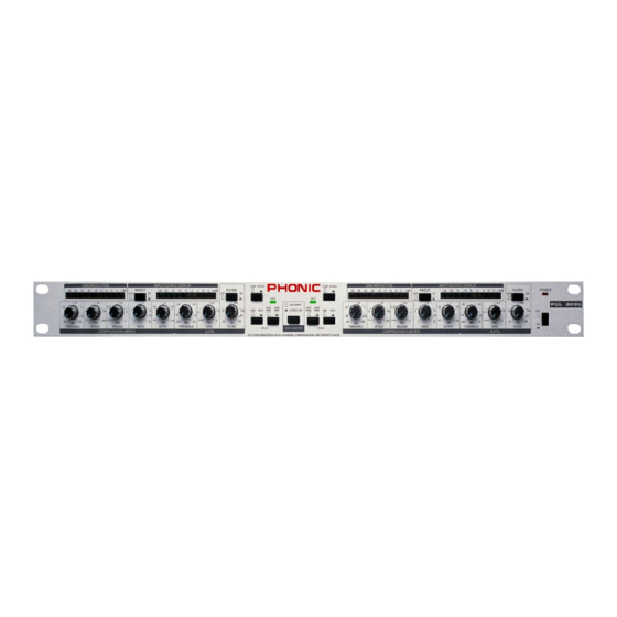
Page 4: Front Panel Description
FRONT-PANEL DESCRIPTION- (CHANNEL A and CHANNEL B are identical.) 8 12 15 9 10 11 COMPRESSOR/LIMITER AREA comparison of compressed signals respond- Compressors and limiters are signal proces- ing to various VR settings. sors that reduce the dynamic range of the signal. -
Page 5: Gate Area
GATE AREA it is pre-factory set. (10) HARD KNEE-SOFT KNEE A noise gate is a signal processor that turns off or In conjunction with ATTACK/RELEASE time significantly attentuates the audio signal passing control, the HARD KNEE creates a harsh com- through it when the signal level falls below a user pressed signal, while the SOFT KNEE creates a adjustable threshold. -
Page 6: Rear Panel Description
PCL3200. The switch shifting changes the way the input/output meter references signals. (18) DC JACK (POWER AC1OV) This unit needs an AC 10V/600mA power supplied by Phonic. Use of any other AC adaptor voids the Mono send to EQ (ring) warranty. -
Page 7: Connection Diagram Discussions
CONNECTION DIAGRAM KEYING PRE AMPLIFIER PRE AMPLIFIER MICROPHONE TAPE RECORDER SYNTHESIZER DE-ESSING PRE AMPLIFIER PRE AMPLIFIER MICROPHONE MICROPHONE CONNECTION DIAGRAM DISCUSSIONS PUT jack. Adjusting the THRESHOLD, The Connection Diagrams (SEE FIGURE F/G) RATIO, ATTACK, and RELEASE controls af- intended as examples of some of the many ways fects signal processing. -
Page 8: System Block Diagram
PCL 3200 BLOCK DIAGRAM PCL 3200... -
Page 9: Specifications
SPECIFICATIONS NOTE : 0 dB = 0.775VRMS +4 dB = 1.23VRMS -10 dB = 0.316VRMS PCL 3200... - Page 10 Phonic, at its option, shall repair or replace the defective unit covered by this warranty. Please retain the dated sales receipt as evidence of the date of purchase.
Need help?
Do you have a question about the PCL 3200 and is the answer not in the manual?
Questions and answers