Bogen PCMTIM Manual
Telephone interface module for bogen's pcm2000 zone paging system
Hide thumbs
Also See for PCMTIM:
- Supplementary manual (2 pages) ,
- User manual (36 pages) ,
- Configuration (2 pages)

Related Manuals for Bogen PCMTIM


Summary of Contents for Bogen PCMTIM
- Page 1 Bogen Model PCMTIM Telephone Interface Module for Bogen's PCM2000 Zone Paging System © 2010 Bogen Communications, Inc. All rights reserved. 54-5946-01B 1002...
- Page 2 PCMTIM UL Approved Notice Every effort was made to ensure that the information in this manual was complete and accurate at the time of printing. However, information is subject to change. Federal Communications Commission (FCC) Statement (Part 68) This equipment is component registered with the Federal Communications Com- mission (FCC) in accordance with Part 68 of its rules.
- Page 3 PCMTIM Important Safety Information Always follow these basic safety precautions when installing and using the system: 1. Read and understand all instructions. 2. Follow all warnings and instructions marked on the product. 3. DO NOT block or cover the ventilation slots and openings. They prevent the product from overheating.
-
Page 4: Table Of Contents
PCMTIM Contents Section 1 - Connecting the Telephone Interface Description....................5 Interface......................5 PBX Station Access/CO Line..............6 PBX Loop Start Trunk Port ................8 PBX Ground Start Trunk Port ..............10 Page Port Contact Closure ..............12 Page Port VOX ..................13 Override....................15 Night Ring ....................16 Section 2 - Accessing Paging Zones Zone Accessing ..................17 To Page a Zone ..................17... -
Page 5: Section 1 - Connecting The Telephone Interface
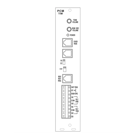
Section 1 - Connecting The Telephone Interface Description The Bogen Model PCMTIM is the Telephone Interface Module for the Bogen PCM Zone Paging System. Only one PCMTIM module is required per system (1 through 99 zones). The PCMTIM provides the telephone interface (including talk battery), night ringer input, emergency override input, background music source input, and auxiliary relay contacts for the system. -
Page 6: Pbx Station Access/Co Line
PCMTIM PBX Station Access/CO line In the PBX Station Access/CO line configuration, the unit answers after the first full ring. As soon as it answers, the default timer is started. The default timer determines the maximum length of any page. When a paging zone is selected, the VOX timer is started (if enabled). - Page 7 PCMTIM 3. Use a modular RJ11 telephone cord (minimum 2-conductor) to connect the mod- ule to the phone system. The two center conductors are Tip and Ring and are not polarity sensitive (see illustration below). Plug one end of the cord in to the PBX or CO modular jack and the other end in to the STATION jack on the module.
-
Page 8: Pbx Loop Start Trunk Port
PCMTIM PBX Loop Start Trunk Port In the PBX Loop Start Trunk Port configuration, the unit supplies a 48V talk battery and detects loop current. There are two modes of operation for Loop Start Trunk. When the unit detects a loop resistance between Tip and Ring, it activates. - Page 9 PCMTIM 3. Use a modular telephone cord to connect the module to the phone system. Plug one end of the cord into the Loop Start Trunk (using a modular jack) and the other end in to the TRUNK jack on the module. The two center conductors are Tip and Ring 48V DC and have a specific polar- ity.
-
Page 10: Pbx Ground Start Trunk Port
PCMTIM PBX Ground Start Trunk Port In the PBX Ground Start Trunk Port configuration, the unit supplies 48V talk battery and detects loop current. When the ground start trunk grounds the PCMʼs Ring, the PCM responds by closing the connection to its Tip, which completes the ac- cess procedure. - Page 11 PCMTIM 3. Use a modular telephone cord to connect the module to the phone system. Plug one end of the cord into the Ground Start Trunk (using a modular jack) and the other end in to the TRUNK jack on the module. The two center conductors are Tip and Ring 48V DC and are polarity sensitive.
-
Page 12: Page Port Contact Closure
PCMTIM Page Port - Contact Closure In the Page Port/Contact Closure configuration, the unit responds to a contact short- ing the +5 contact closure source to its return (see RJ11 figure below). When the short is removed, the page ends. No timers are used in this mode. Audio is provided to the system through a separate pair of leads. -
Page 13: Page Port Vox
PCMTIM Page Port VOX In the Page Port/VOX configuration, a dry audio pair is used to detect audio and ac- tivate the system. Paging ends when the VOX timer or default timer times out. 1. Make sure that the power is OFF and all connections completed before proceeding. - Page 14 PCMTIM 5. Program the Default and VOX timers. See Programming section. Note that the VOX timer can be inhibited, however, Do Not Inhibit the Default Timer or else the system will not drop the page. If this happens, the system power will have to be removed and reconnected.
-
Page 15: Override
PCMTIM Override The Override is a non-programmable feature that lets the caller take priority over all paging functions and make a system-wide page to all speakers. The feature can be activated using a loop start trunk or dedicated telephone. Provisions are also in- cluded to interface with other signaling equipment. -
Page 16: Night Ring
PCMTIM Night Ring The PCM Night Ringer signaling feature is designed to alert personnel to incoming calls after normal business hours. The feature can be activated either by a 90V ring signal or by a contact closure. In the factory default configuration, the night ringer sounds over all zones, however, a zone group can be programmed which will sound the night ringer only over a user-selected group of zones. -
Page 17: Section 2 - Accessing Paging Zones Zone Accessing
PCMTIM Section 2 - Accessing Paging Zones Zone Accessing The PCM system supports from 1 to 99 different paging zones (in groups of 3). It also supports up to 32 paging zone groups for voice paging applications, and 11 zone groups for signaling applications (night ringer, code call, EM/SC, 8 time trig- gers). -
Page 18: To Make An All-Call Page
PCMTIM To Make An All-Call Page 1. Dial the paging access number for your telephone system. 2. Listen for the confirmation tone if enabled (double beep). 3. Dial [0] [0]. 4. Make page and hang up when finished. NOTE: See Programming section to disable All-Call. To Page A Zone Group 1. -
Page 19: To Make A Pattern Code Call
PCMTIM The code calling feature is inhibited as the factory default. An auto repeat feature is provided to repeat the code call once or twice with a 5-second delay between repeats. No paging access is allowed until a code call is complete (including repeats). NOTE: The voice paging function of the PCM system is inhibited during code call- ing. -
Page 20: To Make An Echo Code Call
PCMTIM To Make an Echo Code Call Refer to the Programming section for instructions on how to enable the code call feature and to select the echo code call, and/or enable the auto repeat feature. 1. Dial the paging access number for your telephone system. 2. -
Page 21: Section 3 - Bgm, Tone, Zone & Zone Group Features
PCMTIM Section 3 - BGM, Tone, Zone & Zone Group Features BGM SRC Volume The BGM SRC VOLUME control is only used when a single amplifier provides pag- ing and background music in the system. Background music in all zones will be in- terrupted during a page. -
Page 22: Tones
PCMTIM Tones In addition to the Override and Night Ring tones described previously, the PCM system provides the following additional tones. Confirmation Tone. A double-beep tone heard by the caller after dialing the pag- ing access number and before entering the desired zone number. The default for the tone is enabled. -
Page 23: Tone Notes
PCMTIM Tone Notes The volume level of all of the tones are controlled by the single TONE VOLUME control on the PCMTIM module. All tones will sound at same level. Clockwise ro- tation of the control increases the level. Counterclockwise rotation of the control decreases the level. -
Page 24: Section 4 - Programming System Programming
PCMTIM Section 4 - Programming System Programming System Programming lets you set certain PCM system operations and tone fea- tures using the DTMF keys of a telephone. It also lets you program paging zone groups and signaling zone groups. NOTE: Paging and tone signaling are not allowed during programming. Recommended Initial Programming Procedure All programming is accomplished through the TRUNK jack, using whatever inter- face has been installed. - Page 25 PCMTIM NOTE: After you have entered a Feature Code (and any other data), you must press the [#] key to enter it into the system. If the system accepts the code (and data), you will hear a short double beep. You can then continue with the next Fea- ture Code immediately after the double beep by following the same procedure.
-
Page 26: Programming Paging Zone Groups
PCMTIM Programming Paging Zone Groups 32 paging zone groups can be created. Each zone group can consist of up to 99 zones. To create a zone group: 1. Dial [*] followed by the 2-digit number of the zone group (01 - 32) you want to cre- ate. -
Page 27: Interface Vox Timer
PCMTIM Interface VOX Timer If the PCM system is connected to a PBX station port, loop start, ground start, or Page Port Vox, you can set the default timer for the VOX timeout. The default value is 6 seconds. To change the time, enter the Feature Code followed by a single digit from 1 to 9, corresponding to 1 to 9 seconds of silence. -
Page 28: Clock Synchronization
PCMTIM 24:00 Hour Time Chart 00:00 - Midnight 08:00 - 8 am 16:00 - 4 pm 01:00 - 1 am 09:00 - 9 am 17:00 - 5 pm 02:00 - 2 am 10:00 - 10 am 18:00 - 6 pm 03:00 - 3 am 11:00 - 11 am 19:00 - 7 pm... -
Page 29: Reset Default Values
PCMTIM Reset Default Values A Feature Code (999, then #) is available to reset the PCM2000 system to the orig- inal factory default values. Note: All zone groups are also reset. This process takes 5 - 10 seconds. Wait for confirmation tone before hanging up. Feature Codes &... - Page 30 PCMTIM Feature Feature Additional Factory Code Required Data Default Zone Groups Zone Numbers No Zones " " " " Emergency/ Shift Change Zone Group Zone Numbers All-Call No Tone Follow Contact 2 sec. tone 3 sec. tone 3 sec. tone 4 sec.
- Page 31 PCMTIM Feature Feature Additional Factory Code Required Data Default Time Trigger 1 Zone Group Zone Numbers No Zones Inhibit Inhibit Enable HHMM See Note 3 2 sec. tone 3 sec. tone 3 sec. tone 4 sec. tone 5 sec. tone 6 sec.
- Page 32 PCMTIM Feature Feature Additional Factory Code Required Data Default Time Trigger 4 Zone Group Zone Numbers No Zones Inhibit Inhibit Enable HHMM See Note 3 2 sec. tone 3 sec. tone 3 sec. tone 4 sec. tone 5 sec. tone 6 sec.
- Page 33 PCMTIM Feature Feature Additional Factory Code Required Data Default Time Trigger 7 Zone Group Zone Numbers No Zones Inhibit Inhibit Enable HHMM See Note 3 2 sec. tone 3 sec. tone 3 sec. tone 4 sec. tone 5 sec. tone 6 sec.
-
Page 34: Connections To Mic Using Var1
PCMTIM Connections to MIC using VAR1 In this wiring diagram the VAR1 is used as a microphone preamplifier and provides a dry audio feed at an appropriate level to the dry audio input pins of the Override jack. The contact set of the push-to-talk microphone are connected to the contact closure source and return pins of the Override jack which control the activation of the override feature. -
Page 35: Using Night Ring With External Tone Generator
PCMTIM Using Night Ring With External Tone Generator The illustration below shows the use of an external tone generator to supply a tone for the night ring feature. See Programming section and enter the Feature Code for "No Tone" in order to substitute the external deviceʼs tone. -TRIGGER -RESET TONE... - Page 36 HEREBY DISCLAIMED AND EXCLUDED TO THE MAXIMUM EXTENT ALLOWABLE BY LAW. Bogen's liability arising out of the manufacture, sale or supplying of products or their use or dis- position, whether based upon warranty, contract, tort or otherwise, shall be limited to the price of the product.
Need help?
Do you have a question about the PCMTIM and is the answer not in the manual?
Questions and answers