
Related Manuals for Grace m904


Summary of Contents for Grace m904
- Page 1 Rev H m904 firmware Rev 1.04 m904 RCU firmware Rev 1.05 all contents © Grace Design/ Lunatec LLC...
-
Page 2: Table Of Contents
Welcome Thanks for purchasing the Grace Design m904 high fidelity monitoring system. We build all our products to be completely reliable and easy to use, so you can concentrate on producing great sounding audio, not struggling with complicated equipment or difficult to use product manuals. -
Page 3: Important Safety Information
ServIce InformatIon The Grace Design m904 contains no user serviceable components. Contact Grace Design for repair and upgrade information. In the event that your Grace Design m904 needs to be returned to the factory, contact us for a return authorization number. -
Page 4: M904 Key Features
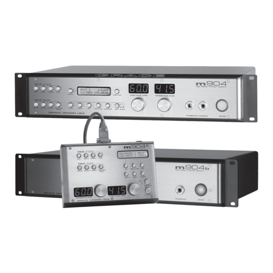
BAL1 BAL 2 UNBAL headphone level select calibrate main level / edit input digital mute mono mon cue talkback spkr select AES31 AES3 S/PDIF TOSLINK/ ADAT power GRACE DESIGN USA headphone outputs frontpanel GRACE DESIGN USA headphone power... - Page 5 INPUT ANALOG SWITCHES This row of four green LED illuminated switches is for selecting be- tween and monitoring any of the analog sources connected to the m904. INPUT DIGITAL SWITCHES This row of four green LED illuminated switches is for selecting be- tween and monitoring any of the digital sources connected to the m904.
-
Page 6: M 904/ M904 B Rearpanel
SEL SWITCH The SEL switch is used to select between Word Clock, Super Clock or Loop-Sync clock when an external clock reference source is used. 904/ m904 rearpanel GRACE DESIGN USA WORD CLOCK/ SUPERCLOCK load S/PDIF OUT... -
Page 7: M 904 B Remote Control Unit
/ edit talkback GRACE DESIGN USA INPUT ANALOG SWITCHES This row of four green LED illuminated switches is for selecting between and monitoring any of the analog sources connected to the m904. INPUT DIGITAL SWITCHES This row of four green LED illuminated switches is for selecting between and monitoring any of the digital sources connected to the m904. - Page 8 SPKR SEL SWITCH The speaker select switch is used to toggle between the available speaker output sets. Each press of the switch lights the LED associated with each speaker set (1 or 2). MONO SWITCH Pressing this green illuminated switch mono sums the stereo left and right channels. MUTE SWITCH The mute switch is used to fully mute control room / speaker outputs from the m904.
-
Page 9: Unpacking Installing Your M904 System
ReGisTeR yoUR UniT Also, we strongly urge you to register your unit with grace design. We provide a limited 5 year warranty on all of our products, but if you don’t register your system it’s hard for us to help you if and when help becomes neces- sary. -
Page 10: System Connections
line VolTaGe selecToR For units with serial numbers 94001 through 940306, line voltage must be selected with a cam. To do this, re- move the AC power chord from the power inlet then use a small screwdriver to pry open the voltage select door. Carefully remove the voltage select cam and re-insert it with the desired voltage showing. - Page 11 TALKBACK MIC INPUT - A standard microphone input which can be used with dynamic or condenser micro- phones. Phantom power (+48V) is available and is software controlled (see CAL mode). CR OUT 1 and CR OUT 2 - A balanced stereo analog CR OUT 1 and CR OUT 2 outputs are provided via male XLR connectors, which connect to your stereo monitor systems.
-
Page 12: Operating The M 904
50’ for headphone use. Be sure to use the supplied 15 pin cable and not an off the shelf computer video cable. If you need a longer cable contact your Grace Design dealer or call us directly. - Page 13 switch again. NOTE: The digital ADAT input is derived from any one of the four channel pairs of an eight channel ADAT interface. The input pair is selected in CAL mode. To choose ADAT input pair do the following: Press the CAL switch. The switch LED will begin to flash, letting you know that CAL mode is now active. Press the optical input switch.
- Page 14 If the incoming digital audio signal or word clock frequency is outside of these tolerances or if an invalid clock source is selected, the s-Lock circuit will not lock and the s-Lock indicator on the system LCD not be visible. Even if the s-Lock does not achieve lock, the digital audio receiver circuits in the m904 can achieve excellent recovered clock jitter performance.
- Page 15 UsinG The mon > cUe FeaTURe Normally, the CUE INPUT signal is routed to the CUE OUTPUT. Pressing the MON > CUE switch when it has not been configured to operate as a third stereo speaker output, as outlined above, routes the currently selected input source that you’re monitoring to the CUE outputs.
- Page 16 level DAC will then be fed from that new source. The DAC output level is set to 0dB as the default value on a new m904 system, but this can easily be changed in CAL mode (see Accessing Cal Modes). mUTe all mode The MUTE switch is located to the immediate left of the mono switch.
-
Page 17: Advanced Features: Accessing The Cal Modes
screenshot 6 phantom power on/ off Press the TALKBACK switch again to access the talkback switch latch setting. Rotating the encoder clockwise turn on latching mode; rotating the encoder counter-clockwise turns off latch mode (momentary) Press the TALKBACK switch again to access the talkback switch latch setting. Rotating the encoder clockwise turn on latching mode;... - Page 18 • Digital Loop-thru output source select • Main Output Level Preset • Headphone Output Level Preset • Cue Output Dimming • 7-Segment Display Brightness Control Table 2 below is provided as a reference to show the factory default settings for items that can be calibrated in your m904 system: Table 2.
- Page 19 To change selected optical inputs, scroll through the following menu by pressing the OPTICAL input switch repeatedly: TOSLINK INPUT OFFSET > ADAT INPUT OFFSET > ADAT SOURCE PAIR SELECT (discussed below) “CAL” will be displayed in the headphone level LED display while the current input source offset level will be shown in the ‘main level/edit’...
- Page 20 “CAL” will be displayed in the headphone level LED display while the current speaker output offset level will be shown in the ‘main level/edit’ LED window. A value of “0” indicates that there is no offset level currently pro- grammed. Rotate the ‘main level/edit’...
- Page 21 CUE OUTPUT LEVEL *GLOBAL* The relative gain range is from 0 to 100dB where “100” is unity gain and 0 is minus infinity. Note that this relative range is the same as the m904’s speaker level settings. This provides a convenient reference for the engineer in setting the CUE output level.
- Page 22 Once you’re satisfied with the new DAC output level value for a given channel, you can select another channel to adjust, select a new function to edit or exit CAL mode. Exit CAL mode and return to the normal operating state by pressing the flashing CAL switch. selecTinG diGiTal loop-ThRU oUTpUT soURce The m904 provides two buffered digital loop-thru outputs.
- Page 23 headphone amplifier gain. The available gain settings are 0dB, 10dB and 20dB. To change the headphone am- plifier gain, do the following: Enter CAL mode by pressing the CAL switch. The switch LED will begin to flash, indicating that you’re now in cali- bration mode.
- Page 24 monitors will DIM. To increase the mic amp gain, rotate the main level encoder in a clockwise direction. As you do this, you’ll see the gain settings change. Preamp gain is adjustable from +10 to +60dB in 3dB steps (except there is no 13dB setting). Rotate the encoder in a counter-clockwise direction to reduce the gain level.
-
Page 25: Additional M 904B Operational Instructions
ReseTTinG The sysTem deFaUlTs There may come a time when you’ll want to reset m904 system parameters to their default values. Here’s how: From normal operating mode, press and hold the CAL switch for approximately 5 seconds. The system LCD will now “ask” you whether or not you’d like to restore the default calibration mode values (screen- shot 20). -
Page 26: Cable And Connector Wiring Diagrams
cleanIng and maIntenance Your m904 system chassis is constructed out of high quality stainless steel. Under normal circumstances, virtually no maintenance is required to keep the unit looking shiny and new. However, if you unit becomes smudged or dirty, here are some cleaning tips: We recommend using either Pledge furniture polish or stainless steel cleaner (availble at your local hardware store). -
Page 27: M904 Block Diagram
m904 block dIagram... -
Page 28: Specifications
SpecIfIcatIonS ANALOG THD+N @ 0dB gain, 1kHz +20dBu out <0.001% (0.00075% typical) +10dBu out <0.003% (0.001% typical) 0dBu out <0.009% (0.005% typical) Intermodulation Distortion SMTPE/DIN 4:1 50Hz, 7kHz @+20dBu out <0.002% (0.0015% typical) @ 0dBu out <0.008% (0.006% typical) Frequency Response +/-3dB 3Hz - 250Khz Dynamic Range... - Page 29 DIGITAL TO ANALOG CONVERTER Output Levels 0dBFS +16dBu / (+24dBu*) Fixed output trim range (0.5dB steps) -95.5dB to +30dB THD+N 1kHz, -1dBFS, 20-22kHz bandwidth <0.002% Dynamic Range 20-22kHz bandwidth >111dB Input Lock Range AES3/SPDIF 32kHz to 192kHz TOSLINK 32kHz to 96kHz ADAT LIGHTPIPE™...
-
Page 30: Warranty Information
• Grace Design warrants all of our products to be free of defective parts and workmanship for a period of five years. This warranty period begins at the original date of purchase and is transferable to any person who may subsequently purchase the product during this time. - Page 31 manUal ReVisions Revision Page Change Date Initials Initial release 04/25/2007 Changed voltage range and power specifications and 06/28/2007 eliminated DC power output saftey marking symbols Added picture of m904b 06/28/2007 changed voltage and fuse information in Table 1 06/28/2007 Added headphone output impedance to spec table 06/28/2007 Changed power consumption and weight specs 06/28/2007...
Need help?
Do you have a question about the m904 and is the answer not in the manual?
Questions and answers