Advertisement
Quick Links
D E S I G N E D
A N D
M A N U F A C T U R E D
B Y
S O N I C
F R O N T I E R S
I N C O R P O R A T E D
2 7 9 0 B R I G H T O N R O A D , O A K V I L L E , O N T A R I O , C A N A D A
L 6 H 5 T 4
T E L : ( 9 0 5 ) 8 2 9 - 3 8 3 8
F A X : ( 9 0 5 ) 8 2 9 - 3 0 3 3
S o n i c
F r o n t i e r s
c a n
b e
r e a c h e d
9 : 0 0
a m
t o
6 : 0 0
p m
( E . S . T . )
o r
2 4
h o u r s
a
d a y
b y
f a c s i m i l e .
Advertisement

Related Manuals for Anthem Audio PRE 1


Summary of Contents for Anthem Audio PRE 1
- Page 1 D E S I G N E D A N D M A N U F A C T U R E D S O N I C F R O N T I E R S I N C O R P O R A T E D 2 7 9 0 B R I G H T O N R O A D , O A K V I L L E , O N T A R I O , C A N A D A L 6 H 5 T 4 T E L : ( 9 0 5 ) 8 2 9 - 3 8 3 8...
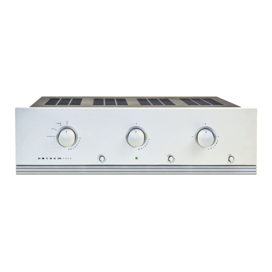
- Page 2 A N T H E M P R E 1 O P E R A T I N G M A N U A L...
- Page 3 T E C H N I C A L S P E C I F I C A T I O N S (Line Stage): < -75 dB Below 1V CHANNE L SEPA R AT I O N : @ 1kHz, < -65dB Below 1V @ 20kHz, (Phono Input to Line (AC line set at 117V 60Hz) Stage Output): <...
- Page 4 We at Sonic Frontiers hope you will derive many years W H A T ’ S I N T H E B O X ? of listening pleasure with your new Anthem Pre 1. This In addition to the Pre 1, the Power Supply (their appro- Operating Manual contains important information regard- priate covers), and the operating manual you are presently ing the operation and care of the Pre 1.
- Page 6 C O N T R O L F U N C T I O N S SELECTOR S WIT CH PREAMPLIFIE R LED This knob is rotated to select a Line Level Input (N) or This Light Emitting Diode has three status conditions the Phono Input (P).
- Page 8 C O N N E C T I O N F U N C T I O N S D E TACHABLE AC PO WER CO RD SOCKET TAPE /EPL INPU T Plug the Detachable Power Cord into this socket (see This input accepts a single-ended RCA input connec- Figure 4).
- Page 9 WARNING- DISCONNECT THE AC INSER TION OF THE TUBE S DETACHABLE POWER CORD FROM THE 1. Using the screwdriver supplied, remove the cover of PRE 1 AND WAIT 5 MINUTES BEFORE the Pre 1. For your convenience, only two of the screws REMOVING COVER, TUBES OR FUSE.
- Page 10 FUSE FUSE LV1 & V1 LV1 & V1 LOCATION LOCATION 6922s 6922s LV2 & V2 LV2 & V2 12AT7s 12AT7s 5AR4 5AR4 LV3 & V3 LV3 & V3 6922s 6922s Hi/Lo gain Hi/Lo gain switching switching SETT ING UP THE P HONO STA G E CARTR IDGE LOADING - RE SIS TA N C E Slide the high/low switches (labeled in the top view In either MM or MC cartridge operating modes, the...
- Page 11 If a tape or other line level recording or processing device CARTR IDG E L OADING - CAPA C I TA N C E With some phono cartridges (both MM and MC), the is being implemented, connect the left and right audio out- addition of some capacitance loading to the cartridge put of the unit to the corresponding left and right Tape/ may prove beneficial in “taming”...
- Page 12 Muting the Pre 1 is achieved by placing the Mute/Operate • The AC power fuse is intact and has not blown. If the fuse button (G) in the MUTE position (button depressed); the has blown, the thin metal conductor will have melted and the output signal is then cut off.
- Page 13 PLACEMENT F OR PROPER VENTILAT I O N DISCLAIMER OF LI ABILITY Allow at least 4” (15 cm) of clear space above the Pre 1 Under no circumstances does Sonic Frontiers, Inc. chassis for proper ventilation, making sure the air vent slots assume liability or responsibility for injury or damages sus- in the chassis cover remain unobstructed.
- Page 14 before any product is returned to our factory for any rea- son. This number must be visible on the exterior of the shipping container(s) for Sonic Frontiers to accept the return. Units shipped to us without a Return Authorization Number or without a visible RA Number on the exterior of the ship- ping container(s) will be returned to the sender, freight collect.
-
Page 15: L E F T C H A N N E L
U P D A T E T O T H E A N T H E M P R E 1 M A N U A L Changes to the location of the high and low gain switches - refer to “SETTING UP THE PHONO STAGE”...
Need help?
Do you have a question about the PRE 1 and is the answer not in the manual?
Questions and answers