Atmos InterSystem HE26 Installation And Servicing Instructions
Hide thumbs
Also See for InterSystem HE26:
- User manual (20 pages) ,
- User operating instructions (4 pages)
Table of Contents
Advertisement
Quick Links
Advertisement
Table of Contents

Related Manuals for Atmos InterSystem HE26


Summary of Contents for Atmos InterSystem HE26
- Page 1 Atmos InterSystem Installation & Servicing Instructions for HE26 (GC 41-249-05) Atmos Heating Systems West March Daventry Northants, NN11 4SA Tel: 01327 871990 Fax: 01327 871905 e-mail: sales@atmos.uk.com internet: www.atmos.uk.com Issue 22.01.10 (Main revision)
- Page 2 © 2010 Atmos Heating Systems The information provided applies to the product in the standard model. Atmos Heating Systems can therefore not be held liable for any damage resulting from the product specifications that deviate from the standard model. The information provided has been compiled with the utmost care. However, Atmos Heating Systems cannot be held liable for any faults in the information nor for the consequences thereof.
-
Page 3: Table Of Contents
TABLE OF CONTENTS 1. Safety Regulations General ..................................7 CH system...................................7 Gas system .................................7 Electrical system .................................7 Domestic water system ...............................7 Flue discharge and air supply .............................7 2. Description of the Appliance General ..................................8 Operation ..................................8 Operating conditions ..............................8 PC interface ................................10 Test programmes ..............................10 3. - Page 4 CH does not reach the correct temperature......................45 9. SERVICING THE BOILER AND COMPONENT REPLACEMENT SERVICING THE BOILER ............................46 COMPONENT REPLACEMENT..........................48 10. Technical Specifications 10.1 Electrical diagram..............................51 11. CE Declaration NOTE The Benchmark Checklist & Service Record are included at the back of the Manual.
- Page 5 This manual Using this manual you can safely install and maintain this appliance. Carefully follow the instructions. In case of doubt, contact Atmos Heating Systems. Keep these instructions near the appliance. Abbreviations and names used Description To be referred to as High Efficiency Atmos InterSystem wall-mounted gas heater Appliance...
- Page 6 Atmos Warranty – Short version 1. Atmos Warranty is against any material, construction or operation faults that are found to be of original manufacturing origin. A full statement of the Atmos Warranty is available (www.atmos.uk.com or 01327 871990). 2. Atmos boiler warranty is, subject to conditions; two years from date of invoice, or 12 months from date of installation;...
-
Page 7: Safety Regulations
SAFETY REGULATIONS The appliance must be installed in accordance with the Gas Safety (Installation and Use) Regulations; October 1994. Failure to install appliances correctly could lead to prosecution. Atmos Heating Systems does not accept any liability for damage or injury caused by not (strictly) observing the current safety regulations and instructions, nor by negligence while installing the Atmos InterSystem wall-mounted gas heater and any accompanying accessories. -
Page 8: Description Of The Appliance
DESCRIPTION OF THE APPLIANCE General The Atmos InterSystem wall-mounted gas boiler is designed for delivering heat to the water of a CH system and, if required, heating hot water via an indirect hot water tank. The air supply and flue discharge can be connected to the appliance by means of two separate pipes or a concentric connection. - Page 9 0 Pump overrun After the operation of the CH, the pump has an overrun. This overrun time is set to the value according to parameter 8 (see § 7.3; factory setting is 1 min). This setting can be changed. Also, the controller will automatically run the pump for 10 seconds, once every 24 hours, to prevent it from getting stuck.
-
Page 10: Pc Interface
temperature and the operation mode can be set with parameters [E] and [E.] (refer to §7.3). PC interface The controller has an interface for a PC. With a special cable and accompanying software, a PC can be connected. This provision makes it possible to follow the behaviour of the controller, the appliance and the heating system during a long period. -
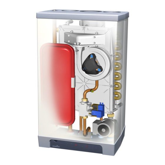
Page 11: Main Components
MAIN COMPONENTS CH pump Flue discharge (or concentric connection) Gas valve Connecting block / terminal list X Clamping plate Condensate discharge Supply sensor S1 Codensate trap Return sensor S2 Heat exchanger Controller operating panel and display Pressure gauge Ionisation/ignition probe 1m connecting cable 230 V ~ Position type plate Manual air vent... -
Page 12: Accessories
Accessories Description Part Ref Pipe mounting bracket 092.537 Connection supply and return 22 mm diameter • Connection gas ½" female thread • Mounting strip boiler • Bag with fixings • Rear mounting frame for top pipe connection 092507 Bottom Pipework cover 092527 Outside sensor for weather compensation 203.207... -
Page 13: Installation
INSTALLATION Overall dimensions CH flow 22 mm diameter 670mm InterSystem HE 26 CH return 22 mm diameter 15 mm diameter 810mm InterSystem HE 26 Flue gas outlet 80 mm diameter Condensate 32 mm dia (after trap 25 mm dia flexib ) le Air supply inlet 80 mm diameter... -
Page 14: Unpacking The Appliance
Unpacking the appliance 1. Unpack the appliance. 2. Check the content of the packaging. This consists of:- • Appliance (A) • Mounting strip (B) • Condensate trap (C) • Installation Instructions • User Operating Instructions • Warranty card 3. Valve set (supplied separately with boiler) comprising 2 x 22mm isolation valves, 1 x gas valve. -
Page 15: Boiler Location
Boiler location Clearances Above casing 200mm min Below casing 230mm min 30mm min 30mm min (in operation) 140mm min (servicing) Front 30mm min (in operation) Front 450mm min (servicing) Keep 50 mm free space above the front panel in order to be able to remove the front panel from the casing. -
Page 16: Mounting
Mounting Depending on the mounting option ordered, the following mounting methods are available:- Mounting strip (A) alone, OR mounting strip (A) and optional pipe mounting bracket (B), OR rear mounting frame (C) and pipe mounting bracket (B), which are both optional items. This arrangement allows for vertical pipework behind the boiler. -
Page 17: Mount The Appliance
4.5.4 Installation connections 1. Make the various connections to the valves (see diagram). 2. Install a filling loop (not supplied) between the cold water inlet pipe and the CH return connection. 3. For most installations, the flexible tube for the safety discharge will be long enough to fit into the condensate discharge waste pipe (see below). -
Page 18: Condensate Disposal
Condensate disposal The appliance is provided with a 25 mm flexible pipe from its condensate trap. As given in §4.6, this should be inserted into an open waste pipe of not less than 32 mm diameter, together with the safety discharge pipe. -
Page 19: Connections
CONNECTIONS Connect the CH system 1. Flush the CH system thoroughly. 2. Connect the flow and return pipes to the mounting bracket. All pipes must be mounted tension-free in order to avoid ticking of the pipes. Existing connections must not be twisted in order to avoid leaks at the connections with the external pipes. -
Page 20: Connecting The Gas Supply
Connecting the gas supply 1. Connect the appliance gas valve to the gas pipe. 2. Check the boiler's data plate to ensure that the appliance has been set for the correct gas supply. The boiler is supplied for Natural Gas (G20). - Page 21 Controller Label and Associated Terminals Note: Terminals X4/11 & 12 are available for OpenTherm modulating stat. 5.3.1 24V dc Electrical connections 24V dc Terminals X4 Description Connector X4 Remarks Room stat 6 - 7 6= +24Vdc Outside temp 8 - 9 sensor OpenTherm 11 - 12...
- Page 22 5.3.3 Outside temperature sensor (Weather compensation option) The appliance has a connection for an outside temperature sensor. The outside temperature sensor can be applied in combination with an on/off room thermostat or time clock. If not using either of these, a wire link must be made across X4/6 &...
-
Page 23: General Flue Requirements
General Flue Requirements 5.4.1 Flue terminal clearances The flue terminal must be sited with minimum clearance distances as shown in the diagram. A terminal guard must be fitted if the terminal is sited less than 2m above ground level, or above a balcony, or accessible flat roof. -
Page 24: Flue Discharge And Air Supply
Note regarding internal air-flue systems. It is recommended that the boiler is sited on or next to an external wall so as to negate the need to use a void or enclosure as a route for the flue system. Where this is not possible the following applies: CORGI have issued a Guidance Document on the safe installation of flue systems within a dwelling. - Page 25 Mounting 60/100mm horizontal concentric terminal 1. Drill hole of diameter 110 mm or larger hole. 2. Cut the terminal to the length required. 3. Slide the terminal into the opening and fit rosettes to cover the opening. 4. Ensure the pipes slope back to the appliance. An alternative telescopic 60/100 horizontal concentric terminal is available from Atmos.
- Page 26 5.5.3 Vertical Concentric connection Straight adapters are available for either 60/100mm or 80/125mm systems. IMPORTANT! Using the concentric adapter set (see photo), the standard two-pipe connection can be changed into a concentric connection. 5. Seal the open air supply connections in the appliance with the sealing cap delivered with the set (item C in photo).
- Page 27 80/125mm Concentric extension for balcony outlet When the free outlet is hindered by an eave, balcony, gallery or anything else, the concentric terminal must be extended to at least the front side of the overhanging part (see diagram). Table of Atmos 80/125mm concentric flue equivalent lengths Maximum equivalent concentric length allowed is 27 metres (Note: Includes an allowance for the terminal;...
- Page 28 5.5.6 80mm twin pipe flue system Refer to the Atmos Price List for the full list of flue components. Terminal The flue discharge at the terminal must be at least 75mm in front of the air intake and the distance between the two pipes at least 75mm.
- Page 29 5.5.7 Plastic twin pipe flue systems NOTE Consult Atmos for these systems. Use of non-approved flue systems will invalidate the guarantee. For special applications, the appliance can be used with plastic flue pipes, which are available from Atmos as follows: PPS.
-
Page 30: Roof Outlet Prefabricated Chimney
Roof outlet prefabricated chimney Appliance category: C33 When there is little space in a shaft, a roof outlet through a prefabricated chimney may be necessary. The prefabricated chimney must comply with the minimum lengths shown. The supplier must guarantee the proper operation of the prefabricated chimney with respect to wind attack, ice formation, rain ingress, etc. -
Page 31: Atmos Ms System
Atmos MS System Appliance category: C53 (individual vertical flue and separate horizontal air inlet). CAUTION The air supply (A) in the outside wall must be provided with an Atmos inlet grid. Flue terminals (B) can be individual, or common terminals can be provided for groups of up to 6 flues. -
Page 32: Atmos Communal Flue System (Cfs)
Atmos Communal Flue System (CFS) A design service is provided for each application. There are different configurations possible and the main ones are illustrated. CFS-NV Naturally ventilated, working under negative pressure CFS-FA Fan assisted, working under positive pressure – smaller diameter pipes are used 5.8.1 Atmos CFS... -
Page 33: Commissioning
COMMISSIONING Note The appliance must be installed and commissioned in accordance with the Fill and de-aerate the appliance and the system manufacturer’s instructions in order to comply with the Building Regs. To demonstrate WARNING compliance, the Benchmark Checklist (located at the back of this Manual) should be Connect the appliance to the mains voltage only after completed and signed at the time of filling and de-aerating! -
Page 34: Commissioning Of The Appliance
Commissioning of the appliance After having carried out the above operations, the appliance can be commissioned. Note 1. Switch on the electrical supply to the appliance. The controls on the display The appliance may carry out a self-test as determined by the controller: for ‘hw’... -
Page 35: System Shutdown
System Shutdown CAUTION Drain the appliance and the system when the mains voltage has been disconnected and there is a chance of freezing. 1. Drain the appliance using the drain tap. 2. Drain the system at the lowest point. 6.3.1 Frost protection •... -
Page 36: Setting And Adjustment
SETTING AND ADJUSTMENT The functioning of the appliance is mainly determined by the (parameter) setting in the appliance controller. A part of this can be set directly via the operating panel, while another part requires an Installer code to be entered before settings can be changed. -
Page 37: Parameters
Parameters Parameter Setting Factory Description setting InterSystem HE 26 Service code [15] Access to installer settings. The service code must be entered (=15). System type 0 = standard 1 = heating only operation + indirect hot water tank (Note: Factory setting is 1. Do not change this setting) 2 = n/a 3 = n/a CH pump continuous... -
Page 38: Setting Maximum Ch Power
Setting maximum CH power The maximum CH power is set to 50% in the factory. When the CH system requires more or less power, the maximum CH power can be changed by adjusting the fan speed. See table: Setting CH power. This table gives the relation between the fan speed and the appliance power. -
Page 39: Weather-Dependent Control
T supply °C Weather-dependent control When the outside sensor is connected, the supply temperature is automatically controlled dependent on the outside temperature in accordance with the set control line. The T set CH (= CH supply temperature) is set via the temperature display. -
Page 40: Setting Gas-Air Control
according to the table below:- Gas type Natural gas H Propane P Gas category 2H G20 3P G31 (propane) % at low position (L) 8.8 – 9.2 9.3 – 9.7 (service and -) % at high position (H) 8.6 – 9.6 9.5 –... -
Page 41: Carbon Monoxide : Carbon Dioxide Ratio
Caution: Check the measuring nipples used for gas tightness. Caution: On windy days or on installations with a long flue run it is necessary to replace the front cover of the boiler in order to obtain an accurate CO measurement Setting the gas valve by pressure measurement This method is less accurate, but usually gives a sufficient result. -
Page 42: Faults
FAULTS When the controller detects a fault, the red fault LED flashes (above the Reset button) and a fault code is shown on the Temperature display. After the fault has been remedied, the controller can be restarted by pressing the Reset button for 5 secs. The following faults are detected and displayed:- Temperature Description... -
Page 43: Burner Does Not Ignite
Burner does not ignite Possible causes Remedies Gas tap is closed 1. Open the gas tap. Air in th e gas pipe. 1. De-aerate the gas pipe. Inlet pressure too low. 1. Contact the gas company. No ignition 1. Replace the ignition probe. No spark. -
Page 44: Burner Resonates
Burner resonates Possible causes Remedies Inlet pressure too low. 1. The house gas meter may be faulty. Contact the gas company. Re-circulation of the flue gases. 1. Check the flue gases and air supply. Gas-air mixture not adjusted properly. 1. Check the adjustment, see Gas-air control. -
Page 45: Reduced Output
Reduced output Possible causes Remedies At high speed, the power has decreased 1. Check appliance and flue system by not more than 5%. for pollution. 2. Clean appliance and flue system. CH does not reach the correct temperature Possible causes Remedies Room thermostat settings not correct. -
Page 46: Servicing The Boiler And Component Replacement
SERVICING THE BOILER AND COMPONENT REPLACEMENT SERVICING THE BOILER The appliance and the system should be serviced annually by a qualified service engineer . For appliances connected to propane gas, a six monthly service for the first two years to simply clean the condensate trap and pipe may be neccessary. - Page 47 Open the gas tap and check the gas couplings below the gas valve and on the mounting bracket for leaks. Switch on the electrical supply to the appliance Switch on the appliance, using the On/Off button on the operating panel. Check the front cover and the connection of the fan to the front cover for leaks.
-
Page 48: Component Replacement
COMPONENT REPLACEMENT 9.2.1 Preparation Switch off the appliance using the On/Off button on the operating panel. Switch off the electrical supply to the appliance. Close the gas tap. Unscrew the two recessed screws left and right at the front underneath the appliance and lift/remove the front panel. - Page 49 9.2.5 Burner/ spark ignition probe Remove the front cover of the heat exchanger as described in § 9.1.2. Unscrew the 4 screws shown on the photo to allow the stainless steel burner mesh to be removed. These screws are Torx 20 (RVS A2 4,2x25”) or Allen bolt M4x20 (units before 2006).
-
Page 50: Technical Specifications
TECHNICAL SPECIFICATIONS Appliance category B13; B33; C13; C 33; C 43; C53; C63; C83 Gas inlet pressure 20 mbar Suitable for gas Technical data InterSystem HE 26 Heat power input (gross)* 8.0 – 30.3 Heat power input (net)* 7.2 – 27.3 Heat output at 80/60°C* 7.0 –... -
Page 51: Electrical Diagram
10.1 Electrical diagram Notes 1. F1: 5x20mm anti-surge fuse, 2A. 2. 230Vac stat circuit: Available for room stat, etc. The switched live can also be used for S plan or Y plan circuits (note that the 230Vac live to the Wiring Centre must come from the same fused spur as the 230Vac supply to the boiler). -
Page 52: Ce Declaration
CE DECLARATION Declaration of conformity according to ISO IEC GUIDE 22. Manufacturer: Atmos Heating Systems Address: West March, DAVENTRY, Northants, NN11 4SA Hereby declares that the application: Atmos, Type InterSystem HE26 Meets the stipulations of the following directives: • Machine directive (89/392/EC) as amended in directive (93/68/EC) •... - Page 56 88167704.doc...
Need help?
Do you have a question about the InterSystem HE26 and is the answer not in the manual?
Questions and answers