
Related Manuals for Atmos Solahart 280HER


Summary of Contents for Atmos Solahart 280HER
- Page 1 280HER Air Sourced Heat Pump Water Heater Owner’s Guide Installation Instructions This water heater must be installed and serviced by a qualified person. Please leave this guide with the householder.
- Page 2 An electronic copy of these Owner’s Guide and Installation Instructions can be downloaded from solahart.com.au. PATENTS This water heater may be protected by one or more patents or registered designs in the name of Solahart Industries Pty Ltd or Rheem Australia Pty Ltd. TRADE MARKS ®...
-
Page 3: Table Of Contents
CONTENTS HOUSEHOLDER This booklet contains important information about your new water heater, including terms of the Solahart warranty. We recommend you read pages 7 to 29, and the terms of the Solahart warranty on pages 4 to 6. The other pages are intended for the installer but may be of interest. Warranty ............................ -
Page 4: Warranty
SOLAHART HEAT PUMP WATER HEATER WARRANTY - AUSTRALIA ONLY - HEAT PUMP WATER HEATER MODELS 280HER 1. THE SOLAHART WARRANTY – GENERAL This warranty is given by Solahart Industries Pty Limited ABN 45 064 945 848 of 1 Alan Street, Rydalmere New South Wales. - Page 5 SOLAHART HEAT PUMP WATER HEATER WARRANTY - AUSTRALIA ONLY - HEAT PUMP WATER HEATER MODELS 280HER Faulty plumbing or faulty power supply. Failure to maintain the water heater in accordance with the Owner's Guide and Installation Instructions. Transport damage. Fair wear and tear from adverse conditions (for example, corrosion). Cosmetic defects.
- Page 6 SOLAHART HEAT PUMP WATER HEATER WARRANTY - AUSTRALIA ONLY - HEAT PUMP WATER HEATER MODELS 280HER Without limiting the periods shown in the table in Clause 3.1, a 5-year whole-of-product warranty applies where a rebate has been received under Solar Victoria’s Solar Homes Program for a water heater installed from the 1 July 2023.
-
Page 7: Safety, Warnings, Installation Notes
SAFETY, WARNINGS, INSTALLATION NOTES It is important you read the following Safety and Warnings, and Relief Valves information. SAFETY AND WARNINGS • The heat pump will operate until a water temperature of 60°C is reached. If the ambient air temperature is outside of the heat pump’s operating range and heating of water is required, an electric heating unit will heat the water to this setting. - Page 8 SAFETY, WARNINGS, INSTALLATION NOTES • In areas where there is a risk of freezing conditions, power must be available to the water heater at all times and the electrical supply to the water heater should not be switched off, otherwise damage could result.
- Page 9 SAFETY, WARNINGS, INSTALLATION NOTES Warning: Water discharged from the temperature pressure relief valve drain line will be hot. Exercise care to avoid any splashing of water by standing clear of the drain line’s point of discharge when operating either valve’s easing lever. DANGER: Failure to operate the easing lever on the relief valve once every six (6) months may result in the water heater cylinder failing, or under certain circumstances, exploding.
-
Page 10: About Your Water Heater
ABOUT YOUR WATER HEATER WATER HEATER APPLICATION This water heater is designed for use in a single family domestic dwelling for the purpose of heating potable water. Its use in an application other than this may shorten its life. MODEL TYPE ®... - Page 11 ABOUT YOUR WATER HEATER Warning: In areas where the ambient air temperature may fall below 4°C, power must be available to the water heater at all times. The water heater has NO WARRANTY for freeze damage if power is unavailable at the water heater. HOW HOT SHOULD THE WATER BE? The system controls (compressor, evaporator and fan) will operate until a water temperature of 60°C.
- Page 12 ABOUT YOUR WATER HEATER TO TURN OFF THE WATER HEATER If it is necessary to turn off the water heater: • Switch off the electrical supply at the water heater isolating switch on the switchboard or at the isolating switch at the water heater. •...
- Page 13 ABOUT YOUR WATER HEATER VICTORIAN CUSTOMERS Notice to Victorian Customers from the Victorian Building Authority. This water heater must be installed by a licensed person as required by the Victorian Building Act 1993. Only a licensed person will give you a Compliance Certificate, showing that the work complies with all the relevant Standards.
-
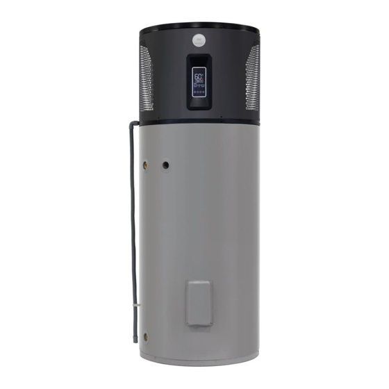
Page 14: Display Panel
DISPLAY PANEL DISPLAY PANEL AND ICONS The water heater has a Display Panel to allow the user to view the current operational status of the water heater and to enable user input functionality. LEDs on the Display Panel illuminate to display icons when there is power to the water heater and the water heater is turned on at the Display Panel. - Page 15 DISPLAY PANEL DISPLAY PANEL – DISPLAY ICONS AND SELECTION KEYS...
- Page 16 DISPLAY PANEL DISPLAY ICONS AND SELECTION KEYS EXPLAINED Icon Keys Description On / Off Key: ** used to switch the water heater “On” or “Off” at the Display Panel and to reilluminate the Display Panel fully after it has dimmed. Main Display Area: illuminates the Average Water Temperature in the water heater in degrees Celsius.
- Page 17 DISPLAY PANEL TURNING THE WATER HEATER “ON” OR “OFF” AT THE DISPLAY PANEL Turn the water heater “On” at the Display Panel • Press the “On / Off” key. The average water temperature in the water heater illuminates in the Main Display Area. The time (if set) illuminates in the Timer / Clock Display Area.
- Page 18 DISPLAY PANEL USEABLE HOT WATER QUANTITY DISPLAY The Display Panel features a Useable Hot Water Quantity display icon. This icon indicates the quantity of usable hot water in the water heater. The more bars illuminated, the more hot water there is available. The display ranges from no illumination of bars, which indicates the average temperature of the water in the water heater is below 36°C, to the illumination of twenty five bars, which indicates the water heater...
- Page 19 DISPLAY PANEL To set the Clock Turn the water heater “Off” at the Display Panel. Press the “On / Off” key. ◼ The displays and icons go out. The Display Screen is blank. Note: If the Display Panel is in the ‘dimmed’ state, it will be necessary to press the “On / Off” key twice.
- Page 20 DISPLAY PANEL To set the Timer Set the Timer ON time. If a Timer period is to be set and ‘oF’ is flashing in the Main Display area, then: Press the “Up” key. ➢ ‘oN’ will commence flashing in the Main Display Area. Press the “Mode”...
- Page 21 DISPLAY PANEL FAULT CODES A fault code will display in the Timer / Clock Display Area in the event the water heater develops a fault. In addition, a one off six (6) second beeping alarm will sound from the Display Panel if a fault code is displayed. The fault code will display alternately with the current time display.
-
Page 22: Maintenance Requirements
MAINTENANCE REQUIREMENTS MINOR MAINTENANCE EVERY SIX MONTHS It is recommended minor maintenance be performed every six (6) months. Minor maintenance can be performed by the dwelling occupant. Switch off the electrical supply at the power outlet to the water heater prior to performing general maintenance. This will prevent the water heater from operating while you clean or spray around the water heater. - Page 23 MAINTENANCE REQUIREMENTS MAJOR SERVICE EVERY FIVE YEARS It is recommended a major service be conducted on the water heater every five (5) years. Warning: Servicing of a water heater must only be carried out by qualified personnel. Phone Your nearest Solahart Dealer.
-
Page 24: Water Supplies
WATER SUPPLIES This water heater must be installed in accordance with this advice to be covered by the Solahart warranty. This water heater is manufactured to suit the water conditions of most public reticulated water supplies. However, there are some known water chemistries which can have detrimental effects on the water heater and its operation and / or life expectancy. - Page 25 WATER SUPPLIES ANODE INSPECTION AND REPLACEMENT The anode installed in your water heater will slowly dissipate whilst protecting the cylinder. The life of the cylinder may be extended by replacing the anode. For water supplies which are either softened or desalinated, or where the water supply may alternate between a water tank and a reticulated public supply or another supply, or where there is a variable supply (e.g.
- Page 26 WATER SUPPLIES SATURATION INDEX (SI) ELECTRIC WATER HEATERS WITHIN WARRANTY SPECIFICATION -1.0 +0.4 +0.8 SATURATION INDEX (calculated @ 80°C water temperature) very corrosive very scaling scaling corrosive SUMMARY OF WATER CHEMISTRY ADVICE AFFECTING WARRANTY The water heater is not suitable for certain water chemistries. Those chemistries are listed below. If the water heater is connected at any time to a water supply with the following water chemistry, the Solahart warranty will not cover any resultant faults: Water Chemistry...
-
Page 27: Save A Service Call
SAVE A SERVICE CALL Check the items below before making a service call. You will be charged for attending to any condition or fault that is not related to manufacture or failure of a part. NOT ENOUGH HOT WATER (OR NO HOT WATER) •... - Page 28 SAVE A SERVICE CALL HEAT PUMP IS NOT OPERATING • Power must be available at the water heater and the water heater switched on. If there is power to the water heater, check the water heater has been turned “On” at the Display Panel. “Turning the Water Heater “On”...
- Page 29 SAVE A SERVICE CALL HIGHER THAN EXPECTED ELECTRICITY BILLS With the installation of your new air sourced heat pump water heater, electrical energy savings can be achieved. Should you at any time, feel your electricity bill is higher than expected, we suggest you check the following points: •...
-
Page 30: Installation
INSTALLATION THIS WATER HEATER IS FOR OUTDOOR INSTALLATION ONLY. THIS WATER HEATER IS NOT SUITABLE FOR POOL HEATING. INSTALLATION STANDARDS The water heater must be installed: • by a qualified person, and • in accordance with the installation instructions, and •... - Page 31 INSTALLATION TRANSPORTING AND HANDLING THE WATER HEATER Take care when handling the water heater. The jacket surrounding the heat pump at the top of the water heater needs to be handled gently so as not to cause damage. Do not tilt the water heater more than 30° from the vertical. Care must be taken during transportation and handling as the water heater is top heavy.
- Page 32 INSTALLATION The water heater must not be installed in an area with a corrosive atmosphere where chemicals are stored or where aerosol propellants are released, as exposure to the corrosive atmosphere may attack the materials used in the water heater and heat pump system. FREEZE PROTECTION The water heater has a freeze protection function built in for extremely cold conditions.
- Page 33 INSTALLATION HOT WATER DELIVERY Warning: This water heater can deliver hot water at temperatures up to 70°C, sufficiently hot to cause severe scalding. Water at this temperature may be plumbed to fixtures where water hotter than 50°C is allowed, such as the kitchen and laundry. The installing plumber may have a legal obligation to ensure the installation of this water heater meets the water temperature delivery requirements of the Plumbing Code of Australia (PCA) so that heated water delivered to fixtures and appliances used primarily for personal hygiene is at a temperature which is unlikely...
- Page 34 INSTALLATION DIMENSIONS AND TECHNICAL DATA Dimensions Model 280HER There is a minimum clearance of 25 mm from a wall behind the water heater...
- Page 35 INSTALLATION Technical Data 280HER Model number Product number – with black anode (magnesium) 280HER24 Refrigerant type R290 Product number – with blue anode (aluminium) 280HER24/B Maximum Refrigerant charge 340 grams Storage capacity litres Refrigerant circuit pressure 2600 kPa Boost capacity – by electric heating unit litres IP Rating IP24...
- Page 36 INSTALLATION TYPICAL INSTALLATION – OUTDOOR LOCATION...
-
Page 37: Connections - Plumbing
CONNECTIONS – PLUMBING All plumbing work must be carried out by a qualified person and in accordance with the Standard AS/NZS 3500.4 and all local codes and regulatory authority requirements. CONNECTION SIZES • Hot water connection: Rp 3/4 • Cold water connection: Rp 3/4 •... - Page 38 CONNECTIONS – PLUMBING PIPE SIZES To achieve true mains pressure operation, the cold water line to the water heater should be the same size or bigger than the hot water line from the water heater. The pipe sizing for hot water supply systems should be carried out by persons competent to do so, choosing the most suitable pipe size for each individual application.
- Page 39 CONNECTIONS – PLUMBING RELIEF VALVE DRAIN DN15 copper drain lines must be fitted to the temperature pressure relief valve and expansion control valve (if one is installed) to carry the discharge clear of the water heater. Connect the drain lines to the valves using disconnection unions.
-
Page 40: Connections - Electrical
CONNECTIONS – ELECTRICAL The power supply to the water heater must not be switched on until the water heater is filled with water and a satisfactory megger reading is obtained. There is NO WARRANTY for the dry firing of the electric heating unit. - Page 41 CONNECTIONS – ELECTRICAL TIMER A Timer function on the Display Panel allows the hours of operation of the water heater to be set. Refer to “Clock and Timer” on page 18. It may be desirable for the heat pump not to operate between certain hours, such as during the peak period when connected to a Time of Use electricity supply due to a more expensive tariff rate applying.
-
Page 42: Commissioning
COMMISSIONING TO FILL AND TURN ON THE WATER HEATER The power supply to the water heater must not be switched on until the water heater is filled with water and a satisfactory megger reading is obtained. • Open all of the hot water taps in the house (don’t forget the shower). •... -
Page 43: Draining The Water Heater
COMMISSIONING It is important to wait for five minutes after the heat pump has activated to ensure it continues to operate and is functioning correctly. Explain to the householder or a responsible officer the functions and operation of the heat pump water heater. Upon completion of the installation and commissioning of the water heating system, leave this guide with the householder or a responsible officer. - Page 44 The information in this section does not replace the Service Instructions for the Solahart 280HER heat pump. The Service Instructions should be referred to for the full and complete procedures for maintenance, repair, decommissioning and disposal of the heat pump.
- Page 45 MAINTENANCE, REPAIR, DECOMMISSIONING, DISPOSAL Evacuation and Removal of the Refrigerant Conventional procedures shall be used if the refrigerant circuit (sealed system) is to be opened. Refrigerant R290 is flammable, therefore the following procedure shall be followed: Evacuate the refrigerant circuit (sealed system) and remove the refrigerant. ◼...
- Page 46 MAINTENANCE, REPAIR, DECOMMISSIONING, DISPOSAL Recovery of Compressor Oil Good practise is to be followed when removing compressor oil during servicing or decommissioning to ensure all oil is removed safely. If the compressor or compressor oil are to be removed, ensure they have been evacuated of refrigerant to an acceptable level to make certain no refrigerant remains within the lubricant.
- Page 47 This page is intentionally blank.
- Page 48 This page is intentionally blank.
-
Page 49: Installation Report
INSTALLATION REPORT Dear Installer / Customer A copy of this installation report filled out in full and signed can be attached to an STC Assignment Form (where applicable) as a method to demonstrate proof of installation. It can be copied and kept for your records. An electronic version may be provided by the Dealer instead. - Page 50 This page is intentionally blank.
- Page 51 This page is intentionally blank.
-
Page 52: Solahart Offices
SOLAHART OFFICES International Headquarters Solahart Industries Pty Ltd International Sales (ABN 45 064 945 848) Telephone International Sales: Registered and Head Office + 61 8 9351 4600 1 Alan Street Facsimile International Sales: Rydalmere, New South Wales, 2116 + 61 8 9351 4698 Australia Email: solahart@solahart.com.au...
Need help?
Do you have a question about the Solahart 280HER and is the answer not in the manual?
Questions and answers