Table of Contents
Advertisement
Advertisement
Table of Contents

Subscribe to Our Youtube Channel
Related Manuals for Actron AutoScanner OBD II Scan Tool CP9575


Summary of Contents for Actron AutoScanner OBD II Scan Tool CP9575
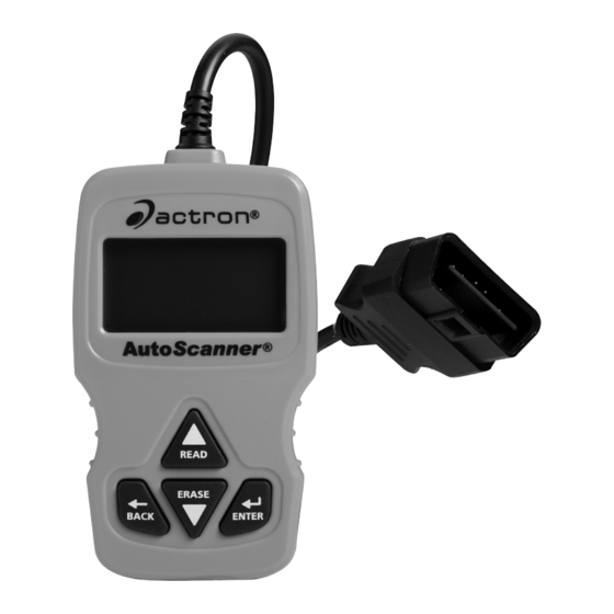
- Page 1 CP9575 Actron AutoScanner ® OBD II Scan Tool ENGLISH...
-
Page 2: Table Of Contents
Contents Safety Precautions ..............3 Signal Words Used ..............3 About the Tool ..............4 Tool Parts ................4 Icons ..................5 Connect the Tool ..............5 Main Menu User Interface ..........6 Read Codes .................6 Vehicle Selection ..............7 Erase Codes .................7 MIL Status ................8 I/M Monitors .................8 Drive Cycle Monitor .............9 View Freeze Data ..............9 Vehicle Information .............9... -
Page 3: Safety Precautions
Safety Precautions This User’s Manual describes the features of the Tool and provides step-by-step instructions for operating the Tool. Always refer to and follow safety messages and test procedures provided by the manufacturer of the vehicle and the Tool. Read the User’s Manual completely before operating the Tool. An undetected or uncorrected vehicle malfunction could cause a serious, even fatal, accident. -
Page 4: About The Tool
• Always turn the ignition key OFF when connecting or disconnecting electrical components, unless otherwise instructed. • Most vehicles are equipped with air bags. If you elect to work around air bag components or wiring, follow your vehicle service manual cautions. You could be seriously injured or killed by an unintended deployment. -
Page 5: Icons
Performs the Erase Codes function and ERASE key scrolls forward through the screens. Press this key when a down arrow () appears on the display. ENTER key Selects displayed items. Returns to the Main Menu or previous screen. BACK key OBD II Connector Connects the Tool to the vehicle connector. -
Page 6: Main Menu User Interface
4. Plug the OBD II Connector attached to the Tool into the vehicle connector. The Tool automatically reads Codes and I/M Monitors and dis- plays the data. When done viewing data, press BACK key to return to Main Menu. MAIN MENU ==================== ... -
Page 7: Vehicle Selection
a faulty component or system. Pending DTCs convert to Diagnostic Trouble Codes when an emissions problem persists long enough to be considered a real problem, not an anomaly. Pending DTCs are indicated by a icon. Vehicle Selection Vehicle Selection will be displayed for Read Codes when a manufacturer specific DTC is retrieved from the vehicle. Erase Codes The Erase function performs the following: 9 Erases Codes (both Diagnostic Trouble Codes and Pending... -
Page 8: Mil Status
MIL Status MIL (Malfunction Indicator Lamp) status indicates if the vehicle com- puter is telling the MIL to illuminate when the engine is running. • MIL ON indicates that the check Engine Light should be ON. • MIL OFF indicates that the Malfunction Indicator Lamp should be OFF. -
Page 9: Drive Cycle Monitor
‰ Since DTCs Cleared - shows status of the monitors since the DTCs were last erased. ‰ This Drive Cycle - shows status of monitors since the start of the current drive cycle. Refer to the vehicle service manual for more detailed information on emission-related monitors and their status. -
Page 10: System Setup
System Setup System Setup allows: • Display contrast to be changed, • Tool information to be viewed, • Display to be checked, • Operation of the keypad to be checked, • Memory of the Tool to be checked, • Language to be changed, • Units of measure to be changed. -
Page 11: Updating Your Tool
(for example a powertrain control module [PCM] and a transmission control module [TCM]. The Tool identifies them by their identification names (ID) assigned by manufacturer (i.e. $10 or $1A). See PID Definitions for more information. Updating Your Tool Download Scanning Suite from http://www.Actron.com/downloads/. Install Scanning Suite. Connect USB Cable to Tool and PC. Start Scanning Suite. Click on Tool Update Icon and follow in- structions. -
Page 12: Pid Definitions
PID Definitions NOTE: The Tool only displays the PIDs the vehicle supports. Tool Description Tool Description ABS FRP Absolute Fuel IGN ADV Ignition Advance Rail Pressure ABS LOAD Absolute Load LT FTRM x Bank x Long Value Term Air To Fuel Ratio Correction Factor ABSLT TPS... - Page 13 Tool Description Tool Description COOLANT Engine Coolant PTO STATUS Power Take Off Status EGR CMD Commanded REL FRP Relative Fuel Exhaust Gas Rail Pressure or Recirculation Vacuum EGR ERR Exhaust Gas REL TPS Relative Or Recirculation Learned Throttle Error Position ENG RUN Engine Run SECOND AIR...
-
Page 14: Spx Limited Warranty
SPX Limited Warranty THIS WARRANTY IS EXPRESSLY LIMITED TO ORIGINAL RETAIL BUYERS OF SPX ELECTRONIC DIAGNOSTIC TOOLS (“UNITS”). SPX Units are warranted against defects in materials and workmanship for one year (12 months) from date of delivery. This warranty does not cover any Unit that has been abused, altered, used for a purpose other than that for which it was intended, or used in a manner inconsistent with instructions regarding use. - Page 16 ©2009 SPX. All Rights Reserved. 0002-000-3106...
Need help?
Do you have a question about the AutoScanner OBD II Scan Tool CP9575 and is the answer not in the manual?
Questions and answers