Table of Contents
Advertisement
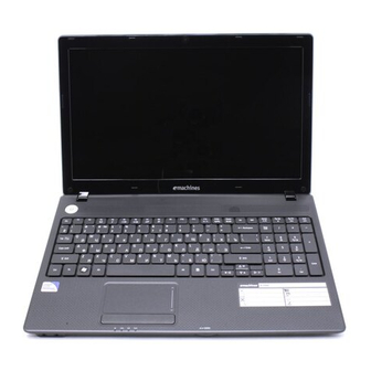
Removing the Battery Pack
1. Turn the computer over. Slide the battery lock in the direction shown.
2. Slide and hold the battery release latch to the release position (1), then lift out the battery pack from the main
unit (2).
NOTE: The battery has been highlighted with a yellow oval as shown in the above image.
Please detach the battery and follow local regulations for disposal.
Chapter 3
2
1
53
Advertisement
Table of Contents

Related Manuals for eMachines D732


Summary of Contents for eMachines D732
-
Page 1: Removing The Battery Pack
Removing the Battery Pack 1. Turn the computer over. Slide the battery lock in the direction shown. 2. Slide and hold the battery release latch to the release position (1), then lift out the battery pack from the main unit (2). NOTE: The battery has been highlighted with a yellow oval as shown in the above image. -
Page 2: Removing The Sd Dummy Card
Removing the SD Dummy Card 1. See “Removing the Battery Pack” on page 53. 2. Push the SD dummy card all the way in to eject it. 3. Pull it out from the slot. Chapter 3... -
Page 3: Removing The Keyboard
Removing the Keyboard NOTE: The model displayed in this service guide may differ in color to the one in your package. 1. See “Removing the Battery Pack” on page 53. 2. Turn the computer over and fully open the lid. There are five (5) securing clips that must be released in order to remove the keyboard. - Page 4 5. Unlock the keyboard FPC and disconnect the cable as shown. Lift the keyboard clear of the chassis. 6. Unlock and disconnect the touchpad FPC from the mainboard: Chapter 3...
-
Page 5: Removing The Odd Module
Removing the ODD Module 1. See “Removing the Battery Pack” on page 53. 2. Remove the one (1) screw securing the ODD module in place. Step Size Quantity Screw Type ODD Module M2.5*6.5 Disassembly 3. Grasp the ODD by the bezel and slide it out of the chassis. Chapter 3... - Page 6 4. Remove the ODD bezel by rotating the top edge downward. 5. Remove the two screws securing the ODD bracket. Step Size Quantity Screw Type ODD Bracket M2.0*3.0 Disassembly 6. Remove the bracket from the ODD. Chapter 3...
-
Page 7: Table Of Contents
Main Unit Disassembly Process Main Unit Disassembly Flowchart NOTE: Use the process highlighted in red to access the Bluetooth module Screw List Step Screw Quantity Part No. Lower Cover M2.5*6.5 86.ARE07.001 Battery Bay M2.0*3.0 86.ARE07.002 WLAN Module Disassembly M2.0*3.0 86.ARE07.002 USB Module Disassembly M2.5*4.0 86.ARE07.002... -
Page 8: Step Screw Quantity
Step Screw Quantity Part No. HDD Carrier Disassembly M3.0*3.5 86.N1407.007 LCD Module Disassembly M2.5*6.5 86.ARE07.001 Thermal Module Disassembly M2.5*4.0 86.R6Z07.001 Mainboard Disassembly M2.5*4.0 86.R6Z07.001 Removing the Lower Cover 1. See “External Modules Disassembly Process” on page 52. 2. Remove the twenty three (23) securing screws from the lower cover. Step Size Quantity... - Page 9 3. Grasp the ODD bay with one hand while holding the lower cover with the other. Lift the lower cover from the device. Chapter 3...
-
Page 10: Disassembly Overview
Disassembly Overview 1. See “Removing the Lower Cover” on page 60. 2. This section is an overview of the major components of the main unit. 7 6 5 Item Description Item Description RTC battery LVDS cable Bluetooth cable Thermal module WLAN module USB module DIMM module(s) -
Page 11: Removing The Dimm Modules
Removing the DIMM Modules 1. See “Disassembly Overview” on page 62. 2. Push out the release latches on both sides of the DIMM socket to release the DIMM module. 3. Remove the DIMM module. 4. Repeat steps for the second DIMM module if present. Chapter 3... -
Page 12: Wlan Module Disassembly M2.0*3.0
Removing the WLAN Module 1. See “Disassembly Overview” on page 62. 2. Disconnect the two (2) cables from the WLAN board. 3. Remove the one (1) screw. Step Size Quantity Screw Type WLAN Module Disassembly M2.0*3.0 Chapter 3... -
Page 13: Removing The Usb Board
4. Detach and remove the WLAN board from the WLAN socket. Removing the USB Board 1. See “Disassembly Overview” on page 62. 2. Unlock and disconnect the USB FFC from the USB board. Repeat for the mainboard connector. Chapter 3... -
Page 14: Usb Module Disassembly M2.5*4.0
3. Remove the one (1) screw from the USB board. Step Size Quantity Screw Type USB Module M2.5*4.0 Disassembly 4. Lift the USB board upward and away from the chassis. Chapter 3... -
Page 15: Removing The Rtc Battery
Removing the RTC Battery 1. See “Disassembly Overview” on page 62. 2. Disconnect the RTC battery cable from the mainboard. 3. Lift the RTC battery away from the mainboard. NOTE: The RTC battery has been highlighted with the yellow circle as shown in the previous image. Please detach the RTC battery and follow local regulations for disposal. -
Page 16: Hdd Module M2-0.4*2
Removing the HDD Module 1. See “Disassembly Overview” on page 62. 2. Remove the one (1) screw securing the HDD module to the mainboard. Step Size Quantity Screw Type HDD Module M2-0.4*2 3. Using the pull-tab, slide the HDD module in the direction of the arrow to disconnect the interface. Chapter 3... - Page 17 4. Remove HDD from the bay. 5. Remove the four (4) screws from the carrier. Step Size Quantity Screw Type HDD Carrier M3.0*3.5 Disassembly 6. Remove the carrier from the HDD. Chapter 3...
-
Page 18: Removing The Lcd Module
Removing the LCD Module 1. See “Disassembly Overview” on page 62. 2. Remove the adhesive ground wire from the fan housing. 3. Remove the WLAN antennas from the cable guides. 4. Unlock and disconnect the LVDS cable. Chapter 3... - Page 19 5. Remove the four (4) screws from the left and right hinges. Step Size Quantity Screw Type LCD Module M2.5*6.5 Disassembly 6. Tilt the upper cover upwards slightly (1) and separate it from the LCD module (2). Chapter 3...
-
Page 20: Removing The Thermal Module
Removing the Thermal Module 1. See “Disassembly Overview” on page 62. 2. Disconnect the fan cable as shown. 3. Loosen the four (4) captive screws (in numerical order from 1 to 4) and remove the one (1) screw from the fan module. -
Page 21: Removing The Cpu
4. Carefully lift up the thermal module assembly and remove it from the mainboard. IMPORTANT:Place the thermal module on a clean, dry surface when it is not installed. Removing the CPU 1. See “Removing the Thermal Module” on page 72. 2. -
Page 22: Removing The Mainboard
3. Carefully lift the CPU clear of the socket. IMPORTANT:Place the CPU on a clean, dry surface when it is not installed. Removing the Mainboard 1. See “Removing the CPU” on page 73. 2. Remove the adhesive tape securing the speaker cable to the mainboard and disconnect the speaker cable from the mainboard connector. - Page 23 3. Remove the one (1) securing screw from the mainboard. Step Size Quantity Screw Type Mainboard M2.5*4.0 Disassembly 4. Lift the mainboard away the lower cover. Chapter 3...
-
Page 24: Removing The Bluetooth Module
Removing the Bluetooth Module 1. See “Removing the Mainboard” on page 74. 2. Turn the mainboard over and locate the Bluetooth module. 3. Disconnect the Bluetooth cable from the mainboard. Chapter 3... - Page 25 4. Lift the Bluetooth module away from the mainboard. 5. Remove the mylar holder to expose the Bluetooth cable connector. Chapter 3...
- Page 26 6. Disconnect the Bluetooth cable from the Bluetooth module. NOTE: Circuit boards >10 cm² have been highlighted with a yellow rectangle as shown in the previous image. Please detach the Circuit board and follow local regulations for disposal. Chapter 3...
-
Page 27: Lcd Module Disassembly Process
LCD Module Disassembly Process LCD Module Disassembly Flowchart Screw List Step Screw Quantity Part No. LCD Bezel M2.5*5.0 86.T23V7.010 Disassembly LCD Panel M2.5*4.0 86.R6Z07.001 Disassembly LCD Hinge M2.0*3.0 86.ARE07.002 Disassembly Chapter 3... -
Page 28: Removing The Lcd Bezel
Removing the LCD Bezel 1. See “Removing the LCD Module” on page 70. 2. Remove the two (2) bezel screws from the LCD module. Step Size Quantity Screw Type LCD Bezel M2.5*5.0 Disassembly 3. Pry the bezel upwards at the top of the LCD module releasing it from the latches. Chapter 3... - Page 29 4. Continue separating the latches along the sides of the bezel towards the hinges. 5. Release the latches at the bottom of the LCD bezel. 6. Lift the bezel clear of the LCD module. Chapter 3...
- Page 30 Removing the Camera (CCD) Module 1. See “Removing the LCD Bezel” on page 80. 2. Lift the CCD module from the LCD cover. 3. Disconnect the cable as shown. NOTE: Take care not to damage the cable. Chapter 3...
-
Page 31: Removing The Lcd Panel
Removing the LCD Panel 1. See “Removing the LCD Bezel” on page 80. 2. Remove the six (6) securing screws from the LCD panel. Step Size Quantity Screw Type LCD Panel M2.5*4.0 Disassembly 3. Remove the LVDS cable from the cable guides. Chapter 3... -
Page 32: Remove The Lcd Hinges
4. Lift the LCD panel clear of the LCD cover as shown. Remove the LCD Hinges 1. See “Removing the LCD Panel” on page 83. 2. Remove the six (6) screws, three on each side. Separate the hinges from the LCD panel. Step Size Quantity... -
Page 33: Removing The Lvds Cable
Removing the LVDS Cable 1. See “Removing the LCD Panel” on page 83. 2. Detach the CCD cable from the back of the LCD panel. 3. Remove the yellow tape securing the LVDS cable. 4. Starting from the top, remove the clear mylar covering and disconnect the LVDS cable from the LCD panel. Chapter 3... -
Page 34: Removing The Wlan Antennas
Removing the WLAN Antennas 1. See “Removing the LCD Panel” on page 83. 2. Remove the black and white WLAN antennas from the cable guides. 3. Remove the black antenna cable from the LCD cover. Repeat for the white antenna. Chapter 3... -
Page 35: Lcd Module Assembly Process
LCD Module Assembly Process Replacing the WLAN Antennas 1. Place the black antenna cable onto the LCD cover as shown. Repeat for the white antenna. 2. Place the black and white WLAN antennas into the cable guides as shown. Chapter 3... -
Page 36: Replacing The Lvds Cable
Replacing the LVDS Cable 1. Turn the LCD panel face down on a non-abrasive, clean surface. Ensure the panel face does not get damaged. Connect the LVDS cable to the LCD panel. Place the clear mylar tape over the connector and press firmly. 2. -
Page 37: Replacing The Lcd Hinges
Replacing the LCD Hinges 1. See “Removing the LCD Panel” on page 83. 2. Replace the four (4) screws, 2 on each side to secure the hinges. Step Size Quantity Screw Type LCD Hinge M2.0*3.0 Assembly Chapter 3... - Page 38 Removing the LCD Panel 1. Place the LCD panel on the LCD cover as shown. 2. Place the LVDS cable into the cable guides. Chapter 3...
- Page 39 3. Replace the six (6) securing screws to secure the LCD panel. Step Size Quantity Screw Type LCD Panel M2.5*4.0 Assembly Chapter 3...
- Page 40 Replacing the Camera (CCD) Module 1. Connect the CCD cable as shown. NOTE: Take care not to damage the cable. 2. Place the CCD module onto the LCD cover. Apply gentle pressure to fix the adhesive. Chapter 3...
-
Page 41: Replacing The Lcd Bezel
Replacing the LCD Bezel 1. Place the bezel hinge covers over the hinges. 2. Ensure the LVDS and WLAN antenna cable bundle are exiting the left hinge as shown. 3. Apply pressure to snap the latches together. Chapter 3... - Page 42 4. Apply pressure along the bottom of the bezel to attach the latches. 5. Apply pressure along the sides of the bezel to attach the latches. 6. Apply pressure along the top of the bezel to attach the latches. Chapter 3...
- Page 43 7. Replace the two (2) bezel screws. Step Size Quantity Screw Type LCD Bezel M2.5*5.0 Assembly Chapter 3...
-
Page 44: Main Unit Assembly Process
Main Unit Assembly Process Replacing the Bluetooth Module 1. Connect the Bluetooth cable to the Bluetooth module. 2. Attach mylar holder to the Bluetooth cable connector. Chapter 3... - Page 45 3. Place the Bluetooth module onto the mainboard. 4. Connect the Bluetooth cable to the mainboard connector. Chapter 3...
-
Page 46: Replacing The Mainboard
Replacing the Mainboard 1. Place the mainboard onto the upper cover. 2. Replace the one (1) screw to secure the mainboard to the upper cover. Step Size Quantity Screw Type Mainboard M2.5*4.0 Assembly Chapter 3... - Page 47 3. Secure the speaker cable to the mainboard using the adhesive tape connected to the cable. 4. Connect the speaker cable to the mainboard. Chapter 3...
-
Page 48: Replacing The Cpu
Replacing the CPU IMPORTANT:The CPU has a Pin1 locator (1) that must be positioned corresponding to the marker (2) on the CPU socket. 1. Place the CPU into the CPU socket as shown, taking note of the Pin1 locator. 2. Using a slotted screw driver, rotate the CPU locking screw 180° clockwise as shown to secure it in the package. -
Page 49: Replacing The Thermal Module
Replacing the Thermal Module IMPORTANT:Apply a suitable thermal grease and ensure all heat pads are in place before replacing the thermal module The following thermal materials are approved for use: • Thermal grease compound • Eapus PSX-D • Thermal pad •... - Page 50 5. Connect the fan cable as shown. Chapter 3...
-
Page 51: Replacing The Lcd Module
Replacing the LCD Module 1. Place the upper cover onto the LCD module and lower into place. Lower the hinges so they are flush with the hinge plates on the upper cover. 2. Replace the four (4) screws to secure the left and right hinges. Step Size Quantity... - Page 52 3. Connect and lock the LVDS cable. 4. Place the WLAN antenna bundle into the cable guides around the fan module. 5. Place the adhesive ground wire attached to the WLAN antenna cable bundle onto the fan housing. Chapter 3...
-
Page 53: Replacing The Hdd Module
Replacing the HDD Module 1. Place the carrier onto the HDD. 2. Replace the four (4) screws to secure the HDD carrier. Step Size Quantity Screw Type HDD Carrier M3.0*3.5 Assembly 3. Place HDD in the HDD bay. Chapter 3... - Page 54 4. Using the pull-tab, slide the HDD module in the direction of the arrow to connect the interface. 5. Replace the one (1) screw to secure the HDD module to the upper cover. Step Size Quantity Screw Type HDD Module M2-0.4*2 Assembly Chapter 3...
-
Page 55: Replacing The Rtc Battery
Replacing the RTC Battery 1. Place the RTC battery onto the mainboard. 2. Connect the RTC battery cable to the mainboard connector. Chapter 3... -
Page 56: Replacing The Usb Board
Replacing the USB Board 1. Place the USB board onto the chassis. 2. Replace one (1) screw to secure the USB board. Step Size Quantity Screw Type USB Board M2.5*4.0 Assembly 3. Connect and lock the USB FFC to the USB board. Repeat for the mainboard connector. Chapter 3... -
Page 57: Replacing The Wlan Module
Replacing the WLAN Module 1. Insert the WLAN board into the WLAN socket. 2. Replace the one (1) screw. Step Size Quantity Screw Type WLAN Board M2.0*3.0 Assembly Chapter 3... - Page 58 3. Connect the two (2) antenna cables to the WLAN board as shown. NOTE: Cable placement is as follows: black (Main) to connector J1, white (AUX) to connector J2. Chapter 3...
-
Page 59: Replacing The Dimm Modules
Replacing the DIMM Modules 1. Insert the DIMM module into the DIMM connector. 2. Press down to lock the DIMM module in place. 3. Repeat steps 1 and 2 for the second DIMM module if present. Chapter 3... -
Page 60: Replacing The Lower Cover
Replacing the Lower Cover 1. Place the lower cover onto the device. 2. Replace the twenty three (23) screws to secure the lower cover to the device. Step Size Quantity Screw Type Lower Cover M2.5*6.5 (red callout) Battery Bay M2.0*3.0 (green callout) Chapter 3... -
Page 61: External Module Assembly Process
External Module Assembly Process Replacing the ODD Module 1. Place the ODD bracket onto the ODD module and replace the two (2) screws to secure it. Step Size Quantity Screw Type ODD Bracket M2.0*3.0 Assembly 2. Press the bezel into the tray, bottom edge first, to secure it to the ODD module. Chapter 3... - Page 62 3. Push the ODD module into the ODD bay until it is flush with the casing. 4. Replace the one (1) screw to secure the module. Step Size Quantity Screw Type ODD Module M2.5*6.5 Assembly Chapter 3...
-
Page 63: Replacing The Keyboard
Replacing the Keyboard 1. Connect and lock the touchpad FFC to the mainboard connector. 2. Place the keyboard face down on the upper cover. Connect the keyboard FPC to the mainboard and secure the locking latch. 3. Turn the keyboard over and slide the front edge into the upper cover, ensuring that the four locating tabs are correctly seated. - Page 64 4. Press down as indicated to secure the keyboard in place. Chapter 3...
-
Page 65: Replacing The Sd Dummy Card
Replacing the SD dummy card 1. Insert the SD dummy card into the slot and push until the card clicks into place and is flush with the casing. Replacing the Battery Pack 1. Insert the battery pack and press down. 2.
Need help?
Do you have a question about the D732 and is the answer not in the manual?
Questions and answers