Table of Contents
Advertisement
Advertisement
Table of Contents

Related Manuals for Asus P5GDC Pro


Summary of Contents for Asus P5GDC Pro
- Page 1 P5GDC...
- Page 2 Product warranty or service will not be extended if: (1) the product is repaired, modified or altered, unless such repair, modification of alteration is authorized in writing by ASUS; or (2) the serial number of the product is defaced or missing.
-
Page 3: Table Of Contents
Contents Notices ....................vii Safety information ................viii Operation safety ................viii P5GDC Pro specifications summary ............ ix Chapter 1: Chapter 1: Product introduction Product introduction Chapter 1: Chapter 1: Chapter 1: Product introduction Product introduction Product introduction Welcome! ................2-1 Package contents .............. - Page 4 Creating a bootable floppy disk ......4-1 4.1.2 ASUS EZ Flash utility ..........4-2 4.1.3 AFUDOS utility ............4-3 4.1.4 ASUS CrashFree BIOS 2 utility ........ 4-5 4.1.5 ASUS Update utility ..........4-7 BIOS setup program ............4-10 4.2.1 BIOS menu screen ..........4-11 4.2.2...
- Page 5 Contents Main menu ................4-13 4.3.1 System Time ............4-13 4.3.2 System Date ............4-13 4.3.3 Legacy Diskette A ..........4-13 4.3.4 Primary, Third, and Fourth IDE Master/Slave ..4-14 4.3.5 IDE Configuration ..........4-15 4.3.6 System Information ..........4-17 Advanced menu ..............
- Page 6 5.2.2 Drivers menu ............5-2 5.2.3 Utilities menu ............5-3 5.2.4 Manuals menu ............5-5 5.2.5 ASUS Contact information ........5-6 5.2.6 Other information ........... 5-6 Software information ............5-8 5.3.1 ASUS MyLogo™ ............5-8 5.3.2 AI Net 2 ..............5-10 5.3.3...
-
Page 7: Notices
Notices Federal Communications Commission Statement Federal Communications Commission Statement Federal Communications Commission Statement Federal Communications Commission Statement Federal Communications Commission Statement This device complies with Part 15 of the FCC Rules. Operation is subject to the following two conditions: • This device may not cause harmful interference, and •... -
Page 8: Safety Information
Safety information Electrical safety Electrical safety Electrical safety Electrical safety Electrical safety • To prevent electrical shock hazard, disconnect the power cable from the electrical outlet before relocating the system. • When adding or removing devices to or from the system, ensure that the power cables for the devices are unplugged before the signal cables are connected. -
Page 9: P5Gdc Pro Specifications Summary
4 MB Flash ROM, AMI BIOS, PnP, DMI2.0, SM BIOS 2.3, WfM2.0 ASUS AI Proactive ASUS AI Proactive ASUS AI Proactive ASUS AI Proactive ASUS AI Proactive ASUS AI NOS™ (Non-delay Overclocking System) Features Features AI Net 2 network diagnosis utility Features Features Features... - Page 10 O v e r c l o c k i n g O v e r c l o c k i n g ASUS AI NOS™ (Non-delay Overclocking System) f e a t u r e s f e a t u r e s...
- Page 11 This chapter describes the motherboard features and the new technologies it supports. Product introduction...
-
Page 12: Package Contents
Chapter summary Welcome! ................1-1 Package contents ..............1-1 Special features ..............1-2 A S U S P 5 G D C P r o A S U S P 5 G D C P r o A S U S P 5 G D C P r o A S U S P 5 G D C P r o A S U S P 5 G D C P r o... -
Page 13: Welcome
P 5 G D C P r o m o t h e r b o a r d ! The motherboard delivers a host of new features and latest technologies, making it another standout in the long line of ASUS quality motherboards! Before you start installing the motherboard, and hardware devices on it, check the items in your package with the list below. -
Page 14: Special Features
Special features 1.3.1 1.3.1 1.3.1 1.3.1 1.3.1 Product highlights Product highlights Product highlights Product highlights Product highlights Latest processor technology Latest processor technology Latest processor technology Latest processor technology Latest processor technology The motherboard comes with a 775-pin surface mount Land Grid Array (LGA) socket designed for the Intel ®... - Page 15 PCI Express™ interface PCI Express™ interface PCI Express™ interface PCI Express™ interface PCI Express™ interface The motherboard fully supports PCI Express, the latest I/O interconnect technology that speeds up the PCI bus. PCI Express features point-to-point serial interconnections between devices and allows higher clockspeeds by carrying data in packets.
-
Page 16: Asus Proactive Features
AI NOS™ (Non-Delay Overclocking System) AI NOS™ (Non-Delay Overclocking System) AI NOS™ (Non-Delay Overclocking System) The ASUS Non-delay Overclocking System™ (NOS) is a technology that auto-detects the CPU loading and dynamically overclocks the CPU speed only when needed. See page 4-21 for details. -
Page 17: Innovative Asus Features
ASUS Hyper Path 2 Technology ASUS Hyper Path 2 Technology ASUS Hyper Path 2 Technology The ASUS Hyper Path 2 technology optimizes the full potential of the Intel ® chipset by shortening the latency time between the CPU and the system memory. - Page 18 1 - 6 1 - 6 C h a p t e r 1 : P r o d u c t i n t r o d u c t i o n C h a p t e r 1 : P r o d u c t i n t r o d u c t i o n 1 - 6 1 - 6 1 - 6...
- Page 19 This chapter lists the hardware setup procedures that you have to perform when installing system components. It includes description of the jumpers and connectors on the motherboard. Hardware information...
- Page 20 Chapter summary Before you proceed .............. 2-1 Motherboard overview ............2-2 Central Processing Unit (CPU) ..........2-6 System memory ..............2-13 Expansion slots ..............2-21 Jumpers ................2-24 Connectors ................. 2-27 A S U S P 5 G D C P r o A S U S P 5 G D C P r o A S U S P 5 G D C P r o A S U S P 5 G D C P r o...
-
Page 21: Before You Proceed
LED. P5GDC PRO SB_PWR1 Standby Powered P5GDC PRO Onboard LED Power A S U S P 5 G D C P r o A S U S P 5 G D C P r o 2 - 1 2 - 1... -
Page 22: Motherboard Overview
P5GDC PRO 2 - 2... -
Page 23: Motherboard Layout
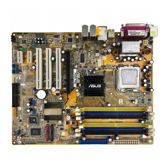
USB1 USB2 LAN_USB34 Top:Rear Speaker Out Intel PWR_FAN1 Center: Side Speaker Out MCH 915P Below: Center/Subwoofer Top:Line In Center:Line Out Below:Mic In P5GDC PRO CHA_FAN2 Marvell 88E8053 PCIEX16 PCI1 Intel SATA3 SATA4 ICH6R PCI2 SATA1 SATA2 CR2032 3V Lithium Cell... -
Page 24: Layout Contents
2.2.4 2.2.4 2.2.4 Layout Contents Layout Contents Layout Contents 2.2.4 2.2.4 Layout Contents Layout Contents S l o t s S l o t s S l o t s S l o t s S l o t s P a g e P a g e P a g e... - Page 25 I n t e r n a l c o n n e c t o r s I n t e r n a l c o n n e c t o r s I n t e r n a l c o n n e c t o r s P a g e P a g e P a g e...
-
Page 26: Central Processing Unit (Cpu)
Contact your retailer immediately if the PnP cap is missing, or if you see any damage to the PnP cap/socket contacts/motherboard components. ASUS will shoulder the cost of repair only if the damage is shipment/ transit-related. •... - Page 27 Press the load lever with your thumb (A), then move it to the left (B) until it is released from the retention tab. R e t e n t i o n t a b R e t e n t i o n t a b R e t e n t i o n t a b R e t e n t i o n t a b R e t e n t i o n t a b...
- Page 28 Close the load plate (A), then push the load lever (B) until it snaps into the retention tab. The CPU fits in only one correct orientation. DO NOT force the CPU into the socket to prevent bending the connectors on the socket and damaging the CPU! Notes on Intel Notes on Intel...
-
Page 29: Installing The Cpu Heatsink And Fan
2.3.2 2.3.2 Installing the CPU heatsink and fan Installing the CPU heatsink and fan 2.3.2 2.3.2 2.3.2 Installing the CPU heatsink and fan Installing the CPU heatsink and fan Installing the CPU heatsink and fan The Intel ® Pentium ® 4 LGA775 processor requires a specially designed heatsink and fan assembly to ensure optimum thermal condition and performance. - Page 30 Connect the CPU fan cable to the connector on the motherboard labeled CPU_FAN1. CPU_FAN1 P5GDC PRO Do not forget to connect the CPU fan connector! Hardware monitoring errors can occur if you fail to plug this connector. 2 - 1 0...
-
Page 31: Uninstalling The Cpu Heatsink And Fan
2.3.3 2.3.3 2.3.3 Uninstalling the CPU heatsink and fan Uninstalling the CPU heatsink and fan Uninstalling the CPU heatsink and fan 2.3.3 2.3.3 Uninstalling the CPU heatsink and fan Uninstalling the CPU heatsink and fan To uninstall the CPU heatsink and fan: Disconnect the CPU fan cable from the connector on the motherboard. - Page 32 Carefully remove the heatsink and fan assembly from the motherboard. Rotate each fastener clockwise to ensure correct orientation when reinstalling. N a r r o w e n d o f t h e g r o o v e N a r r o w e n d o f t h e g r o o v e N a r r o w e n d o f t h e g r o o v e N a r r o w e n d o f t h e g r o o v e...
-
Page 33: System Memory
DDR_A2 DDR_A1 P5GDC PRO DIMM sockets d o n o t u s e D D R a n d D D R 2 d o n o t u s e D D R a n d D D R 2... - Page 34 Recommended DDR memory configurations Recommended DDR memory configurations Recommended DDR memory configurations Recommended DDR memory configurations Recommended DDR memory configurations For dual-channel configuration, the total size of memory module(s) installed per channel must be the same to ensure optimum performance. (DDR_A1 + DDR_A2 = DDR_B1 +DDR_B2) C h a n n e l C h a n n e l...
- Page 35 DDR (400 MHz) Qualified Vendors List DDR (400 MHz) Qualified Vendors List DDR (400 MHz) Qualified Vendors List DDR (400 MHz) Qualified Vendors List DDR (400 MHz) Qualified Vendors List D I M M s u p p o r t D I M M s u p p o r t D I M M s u p p o r t D I M M s u p p o r t...
- Page 36 DDR (400 MHz) Qualified Vendors List DDR (400 MHz) Qualified Vendors List DDR (400 MHz) Qualified Vendors List DDR (400 MHz) Qualified Vendors List DDR (400 MHz) Qualified Vendors List D I M M s u p p o r t D I M M s u p p o r t D I M M s u p p o r t D I M M s u p p o r t...
- Page 37 DDR2 (533MHz) Qualified Vendors List DDR2 (533MHz) Qualified Vendors List DDR2 (533MHz) Qualified Vendors List DDR2 (533MHz) Qualified Vendors List DDR2 (533MHz) Qualified Vendors List D I M M s u p p o r t D I M M s u p p o r t D I M M s u p p o r t D I M M s u p p o r t D I M M s u p p o r t...
- Page 38 DDR2-533 with 600 MHz capability (overclocking) DDR2-533 with 600 MHz capability (overclocking) DDR2-533 with 600 MHz capability (overclocking) DDR2-533 with 600 MHz capability (overclocking) DDR2-533 with 600 MHz capability (overclocking) D I M M s u p p o r t D I M M s u p p o r t D I M M s u p p o r t D I M M s u p p o r t...
-
Page 39: Installing A Ddr Dimm
2.4.3 2.4.3 2.4.3 Installing a DDR DIMM Installing a DDR DIMM Installing a DDR DIMM 2.4.3 2.4.3 Installing a DDR DIMM Installing a DDR DIMM Make sure to unplug the power supply before adding or removing DIMMs or other system components. Failure to do so may cause severe damage to both the motherboard and the components. -
Page 40: Installing A Ddr2 Dimm
2.4.5 2.4.5 Installing a DDR2 DIMM Installing a DDR2 DIMM 2.4.5 2.4.5 2.4.5 Installing a DDR2 DIMM Installing a DDR2 DIMM Installing a DDR2 DIMM Unplug the power supply before adding or removing DIMMs or other system components. Failure to do so can cause severe damage to both the motherboard and the components. -
Page 41: Expansion Slots
Expansion slots In the future, you may need to install expansion cards. The following sub-sections describe the slots and the expansion cards that they support. Make sure to unplug the power cord before adding or removing expansion cards. Failure to do so may cause you physical injury and damage motherboard components. -
Page 42: Interrupt Assignments
2.5.3 2.5.3 2.5.3 2.5.3 2.5.3 Interrupt assignments Interrupt assignments Interrupt assignments Interrupt assignments Interrupt assignments Standard interrupt assignments Standard interrupt assignments Standard interrupt assignments Standard interrupt assignments Standard interrupt assignments I R Q I R Q I R Q I R Q I R Q P r i o r i t y P r i o r i t y... -
Page 43: Pci Slots
2.5.4 2.5.4 2.5.4 PCI slots PCI slots PCI slots 2.5.4 2.5.4 PCI slots PCI slots The PCI slots support cards such as a LAN card, SCSI card, USB card, and other cards that comply with PCI specifications. The figure shows a LAN card installed on a PCI slot. -
Page 44: Jumpers
Normal Clear CMOS (Default) P5GDC PRO Clear RTC RAM You do not need to clear the RTC when the system hangs due to overclocking. For system failure due to overclocking, use the C.P.R. (CPU Parameter Recall) feature. Shut down and reboot the system so the BIOS can automatically reset parameter settings to default values. - Page 45 (Default) P5GDC PRO USBPW56 USBPW78 +5VSB P5GDC PRO USB device wake-up (Default) • The USB device wake-up feature requires a power supply that can provide 500mA on the +5VSB lead for each USB port; otherwise, the system would not power up.
- Page 46 +5VSB (Default) P5GDC PRO P5GDC PRO Keyboard power setting 2 - 2 6 2 - 2 6 C h a p t e r 2 : H a r d w a r e i n f o r m a t i o n...
-
Page 47: Connectors
Connectors 2.7.1 2.7.1 2.7.1 2.7.1 2.7.1 Rear panel connectors Rear panel connectors Rear panel connectors Rear panel connectors Rear panel connectors 1 . 1 . P S / 2 m o u s e p o r t ( g r e e n ) . P S / 2 m o u s e p o r t ( g r e e n ) . - Page 48 8 . 8 . M i c r o p h o n e p o r t ( p i n k ) . M i c r o p h o n e p o r t ( p i n k ) . M i c r o p h o n e p o r t ( p i n k ) .
-
Page 49: Internal Connectors
NOTE: Orient the red markings on the floppy ribbon cable to PIN 1. P5GDC PRO Floppy disk drive connector A S U S P 5 G D C P r o A S U S P 5 G D C P r o... - Page 50 P5GDC PRO (usually zigzag) on the IDE ribbon cable to PIN 1. P5GDC PRO IDE connector 2 - 3 0 2 - 3 0 C h a p t e r 2 : H a r d w a r e i n f o r m a t i o n...
-
Page 51: Hard Disk Drives
SATA1 SATA2 P5GDC PRO SATA connectors I m p o r t a n t n o t e s o n S e r i a l A T A I m p o r t a n t n o t e s o n S e r i a l A T A... - Page 52 +12V CHA_FAN2 Rotation +12V CHA_FAN1 P5GDC PRO Fan connectors Rotation +12V 2 - 3 2 2 - 3 2 C h a p t e r 2 : H a r d w a r e i n f o r m a t i o n...
- Page 53 P5GDC PRO PIN 1 P5GDC PRO Serial port connector 6 . 6 . U S B c o n n e c t o r s ( 1 0 - 1 p i n U S B 5 6 , U S B 7 8 )
- Page 54 PSON# Ground Ground +3 Volts -12 Volts P5GDC PRO ATX power connectors +3 Volts +3 Volts 2 - 3 4 2 - 3 4 C h a p t e r 2 : H a r d w a r e i n f o r m a t i o n...
- Page 55 P5GDC PRO P5GDC PRO CD audio connector 9 . 9 . G A M E / M I D I p o r t c o n n e c t o r ( 1 6 - 1 p i n G A M E )
- Page 56 CHASSIS1 P5GDC PRO (Default) P5GDC PRO Chassis intrusion connector 2 - 3 6 2 - 3 6 C h a p t e r 2 : H a r d w a r e i n f o r m a t i o n...
- Page 57 Azalia-compliant pin definition Legacy AC’97-compliant pin definition P5GDC PRO AAFP P5GDC PRO Analog front panel connector • We recommend that you connect a high-definition front panel audio module to this connector to avail of the motherboard’s high-definition audio capability. •...
- Page 58 Reset IDE_LED PWRSW P5GDC PRO System panel connector The sytem panel connector is color-coded for easy connection. Refer to the connector description below for details. S y s t e m p o w e r L E D ( G r e e n 3 - p i n P L E D ) S y s t e m p o w e r L E D ( G r e e n 3 - p i n P L E D ) •...
- Page 59 This chapter describes the power up sequence, the vocal POST messages, and ways of shutting down the system. Powering up...
-
Page 60: Chapter Summary
Chapter summary Starting up for the first time ..........3-1 Powering off the computer ..........3-2 A S U S P 5 G D C P r o A S U S P 5 G D C P r o A S U S P 5 G D C P r o A S U S P 5 G D C P r o A S U S P 5 G D C P r o... -
Page 61: Starting Up For The First Time
Starting up for the first time After making all the connections, replace the system case cover. Be sure that all switches are off. Connect the power cord to the power connector at the back of the system chassis. Connect the power cord to a power outlet that is equipped with a surge protector. -
Page 62: Powering Off The Computer
Powering off the computer 3.2.1 3.2.1 3.2.1 3.2.1 3.2.1 Using the OS shut down function Using the OS shut down function Using the OS shut down function Using the OS shut down function Using the OS shut down function If you are using Windows ®... -
Page 63: Chapter 4: Bios Setup
This chapter tells how to change the system settings through the BIOS Setup menus. Detailed descriptions of the BIOS parameters are also provided. BIOS setup... - Page 64 Chapter summary Managing and updating your BIOS ........4-1 BIOS setup program ............4-10 Main menu ................4-13 Advanced menu ..............4-18 Power menu ................ 4-31 Boot menu ................4-36 Exit menu ................4-40 A S U S P 5 G D C P r o A S U S P 5 G D C P r o A S U S P 5 G D C P r o A S U S P 5 G D C P r o...
-
Page 65: Managing And Updating Your Bios
Refer to the corresponding sections for details on these utilities. Save a copy of the original motherboard BIOS file to a bootable floppy disk in case you need to restore the BIOS in the future. Copy the original motherboard BIOS using the ASUS Update or AFUDOS utilities. 4.1.1 4.1.1... -
Page 66: Asus Ez Flash Utility
ASUS EZ Flash utility ASUS EZ Flash utility The ASUS EZ Flash feature allows you to update the BIOS without having to go through the long process of booting from a floppy disk and using a DOS-based utility. The EZ Flash utility is built-in the BIOS chip so it is accessible by pressing <Alt>... -
Page 67: Afudos Utility
4.1.3 4.1.3 AFUDOS utility AFUDOS utility 4.1.3 4.1.3 4.1.3 AFUDOS utility AFUDOS utility AFUDOS utility The AFUDOS utility allows you to update the BIOS file in DOS environment using a bootable floppy disk with the updated BIOS file. This utility also allows you to copy the current BIOS file that you can use as backup when the BIOS fails or gets corrupted during the updating process. - Page 68 Updating the BIOS file To update the BIOS file using the AFUDOS utility: Visit the ASUS website (www.asus.com) and download the latest BIOS file for the motherboard. Save the BIOS file to a bootable floppy disk. Write the BIOS filename on a piece of paper. You need to type the exact BIOS filename at the DOS prompt.
-
Page 69: Asus Crashfree Bios 2 Utility
ASUS CrashFree BIOS 2 utility ASUS CrashFree BIOS 2 utility The ASUS CrashFree BIOS 2 is an auto recovery tool that allows you to restore the BIOS file when it fails or gets corrupted during the updating process. You can update a corrupted BIOS file using the motherboard support CD or the floppy disk that contains the updated BIOS file. - Page 70 The utility displays the following message and automatically checks the floppy disk for the original or updated BIOS file. Bad BIOS checksum. Starting BIOS recovery... Checking for floppy... When found, the utility reads the BIOS file and starts flashing the corrupted BIOS file.
-
Page 71: Asus Update Utility
ASUS Update utility ASUS Update utility ASUS Update utility ASUS Update utility The ASUS Update is a utility that allows you to manage, save, and update the motherboard BIOS in Windows ® environment. The ASUS Update utility allows you to: •... - Page 72 Updating the BIOS through the Internet Updating the BIOS through the Internet Updating the BIOS through the Internet To update the BIOS through the Internet: Launch the ASUS Update utility from the Windows ® desktop by clicking S t a r t S t a r t >...
- Page 73 A S U S U p d a t e A S U S U p d a t e A S U S U p d a t e. The ASUS Update main window appears. A S U S U p d a t e...
-
Page 74: Bios Setup Program
The BIOS setup screens shown in this section are for reference purposes only, and may not exactly match what you see on your screen. • Visit the ASUS website (www.asus.com) to download the latest BIOS file for this motherboard and . 4 - 1 0 4 - 1 0... -
Page 75: Bios Menu Screen
4.2.1 4.2.1 BIOS menu screen BIOS menu screen 4.2.1 4.2.1 4.2.1 BIOS menu screen BIOS menu screen BIOS menu screen M e n u i t e m s M e n u i t e m s M e n u i t e m s M e n u i t e m s M e n u i t e m s M e n u b a r... -
Page 76: Menu Items
4.2.4 4.2.4 Menu items Menu items 4.2.4 4.2.4 4.2.4 Menu items Menu items Menu items The highlighted item on the menu System Time [16:37:21] System Date [Tue, 09/21/2004] Legacy Diskette A [1.44M, 3.5 in] bar displays the specific items for Primary IDE Master : [ST320413A] Primary IDE Slave... -
Page 77: Main Menu
Main menu When you enter the BIOS Setup program, the Main menu screen appears, giving you an overview of the basic system information. Refer to section “4.2.1 BIOS menu screen” for information on the menu screen items and how to navigate through them. Use [ENTER], [TAB] or System Time [16:37:21]... -
Page 78: Primary, Third, And Fourth Ide Master/Slave
4.3.4 4.3.4 4.3.4 4.3.4 4.3.4 Primary, Third, and Fourth IDE Master/Slave Primary, Third, and Fourth IDE Master/Slave Primary, Third, and Fourth IDE Master/Slave Primary, Third, and Fourth IDE Master/Slave Primary, Third, and Fourth IDE Master/Slave While entering Setup, the BIOS automatically detects the presence of IDE devices. -
Page 79: Ide Configuration
PIO Mode [Auto] PIO Mode [Auto] PIO Mode [Auto] PIO Mode [Auto] PIO Mode [Auto] Selects the PIO mode. Configuration options: [Auto] [0] [1] [2] [3] [4] DMA Mode [Auto] DMA Mode [Auto] DMA Mode [Auto] DMA Mode [Auto] DMA Mode [Auto] Selects the DMA mode. - Page 80 Enhanced Mode Support On [SATA mode] The default setting SATA allows you to use native OS on Serial ATA and Parallel ATA ports. We recommend that you do not change the default setting for better OS compatibility. In this setting, you may o n l y i f o n l y i f use legacy OS on the Parallel ATA ports o n l y i f...
-
Page 81: System Information
4.3.6 4.3.6 System Information System Information 4.3.6 4.3.6 4.3.6 System Information System Information System Information This menu gives you an overview of the general system specifications. The BIOS automatically detects the items in this menu. AMIBIOS Version : 08.00.10 Build Date : 09/14/04 Processor Type : Genuine Intel(R) CPU 3.20 GHz... -
Page 82: Advanced Menu
A u t o A I N O S A I N O S A I N O S - the ASUS AI Non-delay Overclocking System feature A I N O S A I N O S intelligently determines the system load and automatically boost the performance for the most demanding tasks. - Page 83 S t a n d a r d S t a n d a r d - loads the standard settings for the system. S t a n d a r d S t a n d a r d S t a n d a r d O v e r c l o c k P r o f i l e O v e r c l o c k P r o f i l e - loads overclocking profiles with optimal...
- Page 84 The following items also appear when the A I O v e r c l o c k i n g A I O v e r c l o c k i n g A I O v e r c l o c k i n g A I O v e r c l o c k i n g A I O v e r c l o c k i n g item is set to [AI NOS].
- Page 85 The following item appears only when the A I O v e r c l o c k i n g A I O v e r c l o c k i n g A I O v e r c l o c k i n g A I O v e r c l o c k i n g item is set A I O v e r c l o c k i n g to [Overclock Profile].
-
Page 86: Lan Cable Status
4.4.2 4.4.2 LAN Cable Status LAN Cable Status 4.4.2 4.4.2 4.4.2 LAN Cable Status LAN Cable Status LAN Cable Status The items in this menu display the status of the Local Area Network (LAN) cable. POST Check LAN cable [Disabled] Check LAN cable during POST. -
Page 87: Cpu Configuration
Legacy USB Support [Auto] Legacy USB Support [Auto] Legacy USB Support [Auto] Legacy USB Support [Auto] Legacy USB Support [Auto] Allows you to enable or disable support for USB devices on legacy operating systems (OS). Setting to Auto allows the system to detect the presence of USB devices at startup. - Page 88 VID CMOS Setting [ 62] VID CMOS Setting [ 62] VID CMOS Setting [ 62] VID CMOS Setting [ 62] VID CMOS Setting [ 62] Allows you to set the VID CMOS setting at which the processor is to run. The default value of this item is auto-detected by BIOS.
-
Page 89: Chipset
4.4.5 4.4.5 Chipset Chipset 4.4.5 4.4.5 4.4.5 Chipset Chipset Chipset The Chipset menu allows you to change the advanced chipset settings. Select an item then press <Enter> to display the sub-menu. Advanced Chipset Settings Enable or disable DRAM timing. Configure DRAM Timing by SPD [Enabled] Hyper Path 2 [Auto]... - Page 90 Hyper Path 2 [Auto] Hyper Path 2 [Auto] Hyper Path 2 [Auto] Hyper Path 2 [Auto] Allows you to enable or disable the ASUS Hyper Path 2 feature. Configuration options: [Disabled] [Enabled] [Auto] Graphic Adapter Priority [PCI-Express/PCI] Graphic Adapter Priority [PCI-Express/PCI]...
-
Page 91: Onboard Devices Configuration
4.4.6 4.4.6 4.4.6 Onboard Devices Configuration Onboard Devices Configuration Onboard Devices Configuration 4.4.6 4.4.6 Onboard Devices Configuration Onboard Devices Configuration Configure Win627EHF Super IO Chipset Enable or disable the Azalia controller. Azalia Controller [Enabled] Front Panel Support Type [AC97] Onboard LAN [Enabled] LAN Option ROM [Disabled]... - Page 92 Parallel Port Mode [ECP] Parallel Port Mode [ECP] Parallel Port Mode [ECP] Parallel Port Mode [ECP] Parallel Port Mode [ECP] Allows you to select the Parallel Port mode. Configuration options: [Normal] [Bi-directional] [EPP] [ECP] E C P M o d e D M A C h a n n e l [ D M A 3 ] E C P M o d e D M A C h a n n e l [ D M A 3 ] E C P M o d e D M A C h a n n e l [ D M A 3 ] E C P M o d e D M A C h a n n e l [ D M A 3 ]...
-
Page 93: Pci Pnp
4.4.7 4.4.7 4.4.7 4.4.7 4.4.7 PCI PnP PCI PnP PCI PnP PCI PnP PCI PnP The PCI PnP menu items allow you to change the advanced settings for PCI/PnP devices. The menu includes setting IRQ and DMA channel resources for either PCI/PnP or legacy ISA devices, and setting the memory size block for legacy ISA devices. - Page 94 PCI IDE BusMaster [Enabled] PCI IDE BusMaster [Enabled] PCI IDE BusMaster [Enabled] PCI IDE BusMaster [Enabled] PCI IDE BusMaster [Enabled] Allows BIOS to use PCI bus mastering when reading/writing to IDE devices. Configuration options: [Disabled] [Enabled] IRQ-xx assigned to [PCI Device] IRQ-xx assigned to [PCI Device] IRQ-xx assigned to [PCI Device] IRQ-xx assigned to [PCI Device]...
-
Page 95: Power Menu
Power menu The Power menu items allow you to change the settings for the ACPI and Advanced Power Management (APM). Select an item then press <Enter> to display the configuration options. Select the ACPI state Suspend Mode [S1 (POS) only] used for System Repost Video on S3 Resume [No]... -
Page 96: Apm Configuration
4.5.5 4.5.5 APM Configuration APM Configuration 4.5.5 4.5.5 4.5.5 APM Configuration APM Configuration APM Configuration APM Configuration Go into On/Off or Suspend when Power Power Button Mode [On/Off] button is pressed. Restore on AC Power Loss [Power Off] Power On By RTC Alarm [Disabled] Power On By External Modems [Disabled]... - Page 97 Power On By PCI Devices [Disabled] Power On By PCI Devices [Disabled] Power On By PCI Devices [Disabled] Power On By PCI Devices [Disabled] Power On By PCI Devices [Disabled] When set to [Enabled], this parameter allows you to turn on the system through a PCI LAN or modem card.
-
Page 98: Hardware Monitor
CPU Q-Fan Control [Disabled] CPU Q-Fan Control [Disabled] Allows you to enable or disable the ASUS Q-Fan feature that smartly adjusts the fan speeds for more efficient system operation. When this field is set to [Enabled], the three succeeding items appear. Configuration... - Page 99 CPU Fan Ratio [Auto] CPU Fan Ratio [Auto] CPU Fan Ratio [Auto] CPU Fan Ratio [Auto] CPU Fan Ratio [Auto] Allows you to select the appropriate CPU fan speed ratio for the system. The default [Auto] automatically selects the fan speed ratio when operating a low CPU temperature.
-
Page 100: Boot Menu
Boot menu The Boot menu items allow you to change the system boot options. Select an item then press <Enter> to display the sub-menu. APM Configuration Specifies the Boot Device Boot Priority Boot Device Priority sequence. Boot Settings Configuration Security 4.6.1 4.6.1 Boot Device Priority... -
Page 101: Boot Settings Configuration
This allows you to enable or disable the full screen logo display feature. Configuration options: [Disabled] [Enabled] Set this item to [Enabled] to use the ASUS MyLogo™ feature. Add On ROM Display Mode [Force BIOS] Add On ROM Display Mode [Force BIOS]... -
Page 102: Security
Hit ‘DEL’ Message Display [Enabled] Hit ‘DEL’ Message Display [Enabled] Hit ‘DEL’ Message Display [Enabled] Hit ‘DEL’ Message Display [Enabled] Hit ‘DEL’ Message Display [Enabled] When set to Enabled, the system displays the message “Press DEL to run Setup” during POST. Configuration options: [Disabled] [Enabled] Interrupt 19 Capture [Disabled] Interrupt 19 Capture [Disabled] Interrupt 19 Capture [Disabled]... - Page 103 If you forget your BIOS password, you can clear clear it by erasing the CMOS Real Time Clock (RTC) RAM. See section “2.6 Jumpers” for information on how to erase the RTC RAM. After you have set a supervisor password, the other items appear to allow you to change other security settings.
-
Page 104: Exit Menu
The message “Password Installed” appears after you set your password successfully. To change the user password, follow the same steps as in setting a user password. Clear User Password Clear User Password Clear User Password Clear User Password Clear User Password Select this item to clear the user password. - Page 105 Exit & Save Changes Exit & Save Changes Exit & Save Changes Exit & Save Changes Exit & Save Changes Once you are finished making your selections, choose this option from the Exit menu to ensure the values you selected are saved to the CMOS RAM. An onboard backup battery sustains the CMOS RAM so it stays on even when the PC is turned off.
- Page 106 4 - 4 2 4 - 4 2 4 - 4 2 4 - 4 2 4 - 4 2 C h a p t e r 4 : B I O S s e t u p C h a p t e r 4 : B I O S s e t u p C h a p t e r 4 : B I O S s e t u p C h a p t e r 4 : B I O S s e t u p C h a p t e r 4 : B I O S s e t u p...
- Page 107 This chapter describes the contents of the support CD that comes with the motherboard package. Software support...
- Page 108 Chapter summary Installing an operating system ..........5-1 Support CD information ............5-1 Software information ............5-8 RAID configurations ............5-16 Creating a RAID driver disk ..........5-22 A S U S P 5 G D C P r o A S U S P 5 G D C P r o A S U S P 5 G D C P r o A S U S P 5 G D C P r o...
-
Page 109: Installing An Operating System
The contents of the support CD are subject to change at any time without notice. Visit the ASUS website(www.asus.com) for updates. 5.2.1 5.2.1 Running the support CD Running the support CD 5.2.1... -
Page 110: Drivers Menu
5.2.2 5.2.2 Drivers menu Drivers menu 5.2.2 5.2.2 5.2.2 Drivers menu Drivers menu Drivers menu The drivers menu shows the available device drivers if the system detects installed devices. Install the necessary drivers to activate the devices. QFE Update QFE Update QFE Update QFE Update QFE Update... -
Page 111: Utilities Menu
Marvell Yukon VCT Application Installs the Marvell ® Yukon VCT cable diagnostic application that analyzes and reports LAN cable faults and shorts. See page 5-10 for details. ASUS PC Probe ASUS PC Probe ASUS PC Probe ASUS PC Probe ASUS PC Probe This smart utility monitors the fan speed, CPU temperature, and system voltages, and alerts you of any detected problems. - Page 112 ASUS Update ASUS Update ASUS Update ASUS Update The ASUS Update utility allows you to update the motherboard BIOS in a Windows ® environment. This utility requires an Internet connection either through a network or an Internet Service Provider (ISP). See page 4-7 for details.
-
Page 113: Manuals Menu
5.2.4 5.2.4 Manuals menu Manuals menu 5.2.4 5.2.4 5.2.4 Manuals menu Manuals menu Manuals menu The M a n u a l s M a n u a l s M a n u a l s M a n u a l s menu contains the user manuals for third party components M a n u a l s and applications. -
Page 114: Asus Contact Information
C o n t a c t C o n t a c t C o n t a c t tab to display the ASUS contact information. You can C o n t a c t also find this information on the inside front cover of this user guide. - Page 115 Displays the support CD contents in graphical format. Technical support Form Technical support Form Technical support Form Technical support Form Technical support Form Displays the ASUS Technical Support Request Form that you have to fill out when requesting technical support. Filelist Filelist Filelist Filelist...
-
Page 116: Software Information
5.3.1 ASUS MyLogo™ ASUS MyLogo™ The ASUS MyLogo™ utility lets you customize the boot logo. The boot logo is the image that appears on screen during the Power-On-Self-Tests (POST). The ASUS MyLogo™ is automatically installed when you install the A S U S U p d a t e... - Page 117 R a t i o R a t i o box. When the screen returns to the ASUS Update utility, flash the original BIOS to load the new boot logo. 10. After flashing the BIOS, restart the computer to display the new boot logo during POST.
-
Page 118: Ai Net 2
5.3.2 5.3.2 5.3.2 5.3.2 5.3.2 AI Net 2 AI Net 2 AI Net 2 AI Net 2 AI Net 2 The Marvell ® Virtual Cable Tester™ (VCT) is a cable diagnostic utility that reports LAN cable faults and shorts using the Time Domain Reflectometry (TDR) technology. -
Page 119: C-Media 3D Audio Configuration
5.3.3 5.3.3 C-Media 3D audio configuration C-Media 3D audio configuration 5.3.3 5.3.3 5.3.3 C-Media 3D audio configuration C-Media 3D audio configuration C-Media 3D audio configuration The C-Media 3D Audio Configuration utility allows easy installation and set up of audio devices through a user-friendly interface. The utility is automatically installed when you install the C-Media CMI9880 audio driver and application from the motherboard support CD. - Page 120 S m a r t J a c k S e t t i n g S m a r t J a c k S e t t i n g S m a r t J a c k S e t t i n g. You can configure the function of the rear panel, S m a r t J a c k S e t t i n g S m a r t J a c k S e t t i n g front panel, and digital I/O audio ports from this section.
- Page 121 Effect The E f f e c t E f f e c t E f f e c t E f f e c t tab allows you to control the environment emulation, set the E f f e c t environment size, and adjust the equalizer settings.
-
Page 122: Device Setting
Device Setting The D e v i c e S e t t i n g D e v i c e S e t t i n g D e v i c e S e t t i n g D e v i c e S e t t i n g tab allows you to enable the audio CODEC D e v i c e S e t t i n g multi-streaming feature, select a sound playback, and sound recording... - Page 123 Using Dolby Using Dolby Using Dolby Using Dolby Using Dolby ® Digital Live Digital Live Digital Live Digital Live Digital Live™ The Dolby ® Digital Live™ technology encodes your computer’s digital audio contents to real-time Dolby ® Digital streams. Using the CODEC and the Sony/Philips Digital Interface (S/PDIF) ports on the motherboard, you can send the encoded Dolby ®...
-
Page 124: Raid Configurations
RAID configurations The motherboard comes with the Intel ® ICH6R Southbridge RAID controller that allow you to configure IDE and Serial ATA hard disk drives as RAID sets. The motherboard supports the following RAID configurations. R A I D 0 R A I D 0 R A I D 0 (Data striping) optimizes two identical hard disk drives to read and R A I D 0... -
Page 125: Installing Hard Disks
5.4.1 5.4.1 5.4.1 Installing hard disks Installing hard disks Installing hard disks 5.4.1 5.4.1 Installing hard disks Installing hard disks The motherboard supports Serial ATA hard disk drives. For optimal performance, install identical drives of the same model and capacity when creating a disk array. -
Page 126: Intel ® Raid Configurations
5.4.2 5.4.2 Intel Intel ® ® ® ® ® RAID configurations RAID configurations 5.4.2 5.4.2 5.4.2 Intel Intel Intel RAID configurations RAID configurations RAID configurations This motherboard supports RAID 0, RAID 1, and Intel ® Matrix Storage configurations for Serial ATA hard disks drives through the Intel ®... - Page 127 At the bottom of the screen are the navigation keys. These keys allow you to move through and select menu options. ]-Change [TAB]-Next [ESC] Previous Menu [Enter]-Select Creating a RAID Volume Creating a RAID Volume Creating a RAID Volume Creating a RAID Volume Creating a RAID Volume To create a RAID volume: From the Intel Application Accelerator RAID Option ROM utility main...
- Page 128 T I P : T I P : T I P : For server systems, use of a lower array block size is T I P : T I P : recommended. For multimedia computer systems used mainly for audio and video editing, a higher array block size is recommended for optimum performance.
- Page 129 Press <Del> to delete the RAID volume. The following confirmation message appears. VOLUME DELETE VERIFICATION ALL DATA IN THE VOLUME WILL BE LOST!! Are you sure you want to delete volume "RAID_Volume0"? (Y/N) Press <Y> to confirm or <N> to return to the configuration Main Menu. Resetting RAID Disks Drives Resetting RAID Disks Drives Resetting RAID Disks Drives...
-
Page 130: Creating A Raid Driver Disk
Creating a RAID driver disk A floppy disk with the RAID driver is required when installing Windows ® 2000/XP operating system on a hard disk drive that is included in a RAID set. To create a RAID driver disk: Place the motherboard support CD in the optical drive. When the D r i v e r s D r i v e r s D r i v e r s...
Need help?
Do you have a question about the P5GDC Pro and is the answer not in the manual?
Questions and answers