Table of Contents
Advertisement
Advertisement
Table of Contents

Related Manuals for Asus P5A


Summary of Contents for Asus P5A
- Page 1 Pentium Super7 Motherboard ® USER’S MANUAL...
- Page 2 Product warranty or service will not be extended if: (1) the product is repaired, modified or altered, unless such repair, modification of alteration is authorized in writing by ASUS; or (2) the serial number of the product is defaced or missing.
-
Page 3: Asus Contact Information
WWW: www.asus.com FTP: ftp.asus.com.tw/pub/ASUS ASUS COMPUTER GmbH (Europe) Marketing Address: Harkort Str. 25, 40880 Ratingen, BRD, Germany Telephone: 49-2102-445011 Fax: 49-2102-442066 Email: sales@asuscom.de Technical Support Hotline: 49-2102-499712 BBS: 49-2102-448690 Email: tsd@asuscom.de WWW: www.asuscom.de FTP: ftp.asuscom.de/pub/ASUSCOM ASUS P5A User’s Manual... -
Page 4: Table Of Contents
Item Checklist .................. 7 II. FEATURES ..................8 ASUS P5A Motherboard ..............8 Introduction to ASUS Smart Series Motherboards ....9 Parts of the ASUS P5A Motherboard ..........11 III. INSTALLATION ................12 ASUS P5A Motherboard Layout ............. 12 Installation Steps ................14 1. - Page 5 V. SUPPORT SOFTWARE ..............59 ASUS Smart Motherboard Support CD ........... 59 Desktop Management Interface (DMI) ..........60 Introducing the ASUS DMI Configuration Utility ....60 System Requirements ............60 Using the ASUS DMI Configuration Utility ......61 VI. ASUS CIDB ................... 63 The ASUS CIDB Chassis Sensor ..........
-
Page 6: Federal Communications Commission Statement
Radio Interference Regulations of the Canadian Department of Communications. This Class B digital apparatus complies with Canadian ICES-003. Cet appareil numérique de la classe B est conforme à la norme NMB-003 du Canada. ASUS P5A User’s Manual... -
Page 7: Introduction
Instructions on setting up the BIOS software Support Software Information on the included support software VI. ASUS CIDB Installation of the ASUS CIDB Chassis Sensor (optional) VII. ASUS L101 Card Installation of the ASUS LAN card (optional) APPENDIX Glossary of Terms Item Checklist Please check that your package is complete. -
Page 8: Features
BIOS supports IDE CD-ROM or SCSI device boot-up. • Wake-On-LAN Connector: Supports Wake-On–LAN activity with special network cards, such as the ASUS PCI-L101 10/100 Fast Ethernet PCI card. • PC Health Monitoring (optional): Provides a convenient utility to monitor your system’s vital components/activities, such as fan rotations, voltages, and temperatures. -
Page 9: Introduction To Asus Smart Series Motherboards
Windows 98, must be used. • PC’98 Compliant: Both the BIOS and hardware levels of the ASUS Smart Series motherboards meet PC’98 compliancy. The new PC’98 requirements for systems and components are based on the following high-level goals: Support... - Page 10 Message LED (requires ACPI-supported OS): Chassis LEDs now act as in- formation providers. Through the way a particular LED illuminates, the user can determine the stage the computer is in. A simple glimpse provides useful information to the user. ASUS P5A User’s Manual...
-
Page 11: Parts Of The Asus P5A Motherboard
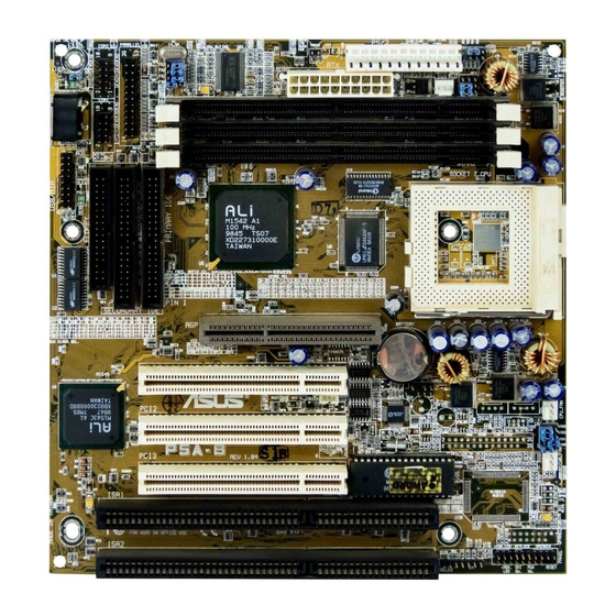
II. FEATURES Parts of the ASUS P5A Motherboard ATX Power ALi Aladdin V 3 DIMM CPU ZIF Socket 7 AGPset Sockets PS/2 Mouse (top) and Keyboard USB Port Serial and Parallel Connectors 512KB/1MB Pipelined Burst L2 Cache Game/MIDI Port (optional) -
Page 12: Installation
III. INSTALLATION ASUS P5A Motherboard Layout Top: Mouse CPU_FAN Bottom: Keyboard Board Power Input KBMS for ATX Power Supply KBPWR Top: USB 1 CPU ZIF Socket 7 Bottom: USB 2 PWR_FAN CPU Thermal Sensor (Hardware Monitor) VID0 VID1 VID2 VID3... - Page 13 The onboard hardware monitor uses the address 290H-297H so legacy ISA cards must not use this address or else conflicts will occur. **If the onboard audio (optional) is selected, PCI Slot 5 can only be used for a PCI slave device. ASUS P5A User’s Manual...
-
Page 14: Installation Steps
RTC data: (1) Turn off your computer, (2) Short solder points using a small metalic object, (3) Turn on your computer, (4) Hold down <Delete> during bootup and enter BIOS setup to re-enter user preferences. CLRTC Short solder points to Clear CMOS P5A Clear RTC RAM ASUS P5A User’s Manual... - Page 15 Disable because not all computers have the appropriate ATX power supply. Your computer will not function if you set this to Enable and if you P5A Keyboard Power Up do not have the right ATX power supply. 3. +3V Voltage Selection (VIO1) This jumper allows you to select the voltage supplied to the DRAM, chipset, AGP, and the CPU’s I/O buffer.
- Page 16 Frequencies above 100MHz exceed the specifications for the on- board chipset and are not guaranteed to be stable. The table on the following page is for general reference purposes only. Always refer to the instructions in- cluded with your CPU when possible. ASUS P5A User’s Manual...
- Page 17 *The only IBM or Cyrix 6x86(L) (or M I) that is supported on this motherboard is revision 2.7 or later (see next page). NOTE: For updated processor settings, visit the ASUS web site (see ASUS CONTACT INFORMA- TION for URLs).
-
Page 18: Compatible Cyrix Cpu Identification
6x86MX ---- 2.9V(Dual) [2-3] [1-2] [1-2] [2-3] Intel P55C-MMX ---- 2.8V(Dual) [2-3] [1-2] [1-2] [1-2] 2.2Volts 2.3Volts 2.4Volts 2.0Volts 2.1Volts 2.5Volts 2.6Volts 2.7Volts 2.8Volts 2.9Volts 3.0Volts 3.1Volts 3.2Volts 3.3Volts 3.4Volts P5A CPU Core Voltage Selection 3.5Volts ASUS P5A User’s Manual... -
Page 19: System Memory (Dimm)
If your DIMMs are not PC100-compliant, set the CPU bus frequency to 66MHz for system stability. • ASUS motherboards support SPD (Serial Presence Detect) DIMMs. This is the memory of choice for best performance vs. stability. • SDRAM chips are generally thinner with higher pin density than EDO (Extended Data Output) chips. -
Page 20: Dimm Memory Installation Procedures
88 Pins 60 Pins 20 Pins Lock P5A 168 Pin DIMM Memory Sockets The DIMMs must be 3.3Volt unbuffered SDRAMs. To determine the DIMM type, check the notches on the DIMMs (see figure below). 168-Pin DIMM Notch Key Definitions (3.3V) -
Page 21: Central Processing Unit (Cpu)
“BUS Frequency Selection” depending on the CPU that you install. CAUTION! Be careful not to scrape the motherboard when mounting a clamp- style processor fan or else damage may occur to the motherboard. Blank Lever Lock P5A ZIF Socket 7 ASUS P5A User’s Manual... - Page 22 (This page was intentionally left blank.) ASUS P5A User’s Manual...
-
Page 23: Expansion Cards
“Resources” tab which shows the Interrupt number and address. Make sure that no two devices use the same IRQs or your computer will experience problems when those two devices are in use at the same time. ASUS P5A User’s Manual... -
Page 24: Assigning Dma Channels For Isa Cards
Accelerated Graphics Port This motherboard provides an accelerated graphics port (AGP) slot to support a new generation of graphics cards with ultra-high memory bandwidth, such as the ASUS AGP-V3000 series of graphics and video accelerators. NOTE: The AGP Mini Port... -
Page 25: External Connectors
The system will direct IRQ12 to the PS/2 mouse if one is detected. If not de- tected, expansion cards can use IRQ12. See “PS/2 Mouse Control” in BIOS Features Setup of the BIOS SOFTWARE. PS/2 Mouse (6-pin Female) ASUS P5A User’s Manual... - Page 26 (Pin 5 is removed to prevent inserting in the wrong orienta- tion when using ribbon cables with pin 5 plugged). NOTE: Orient the red markings on the floppy ribbon cable to PIN 1 PIN 1 P5A Floppy Disk Drive Connector ASUS P5A User’s Manual...
- Page 27 Connect Midi devices for playing or editing audio. Joystick/Midi (15-pin Female) 8. Universal Serial BUS Ports 1 & 2 (Two 4-pin Female Sockets) Two USB ports are available for connecting USB devices. USB 1 Universal Serial Bus (USB) 2 ASUS P5A User’s Manual...
- Page 28 Primary or Secondary IDE connectors will cause the LED to light up. TIP: If the case-mounted LED does not light, try reversing the 2-pin plug. IDELED P5A IDE Activity LED ASUS P5A User’s Manual...
- Page 29 This occurs when a panel switch or light detector is triggered. This function requires the optional ASUS CIDB Chassis Sensor to be installed (see VI. ASUS CIDB) NOTE: When the chassis is opened, connect/short the Chassis Signal pin to the +5VSB pin.
- Page 30 NOTE: The “Ro- tation” signal is to be used only by a specially designed fan with rotation signal. The Rotations per Minute (RPM) can be monitored using ASUS PC Probe Utility or Intel LDCM Utility.
- Page 31 This 2-pin connector connects to the case-mounted key switch to allow key- board locking. 20. Speaker Connector (SPEAKER, 4 pins) This 4-pin connector connects to the case-mounted speaker. System Message Power LED LOCK Keyboard Lock ATX Power Switch Speaker Connector Reset SW SPKR P5A System Panel Connectors ASUS P5A User’s Manual...
- Page 32 21. Wake-on-LAN Activity Connector (3-pin WOLCON) The WOLCON connector allows the system to power up when there is a wakeup packet or signal is received from the network through the ASUS PCI-L101 LAN card (see section VI. ASUS LAN CARD).
- Page 33 This connector allows you to receive stereo audio input from such sound sources as a TV tuner or MPEG card. P5A Stereo Audio In Connector 24. Stereo Audio In Connector (4-pin CD1) This connector allows you to receive stereo audio input from an internal CD-ROM drive.
- Page 34 SMBDATA P5A SMBus Connector 26. Power Supply Temperature External Connector (2 pin TRPWR) This connector allows you to connect a compatible heat sensor to monitor the power supply temperature. TRPWR P5A Power Supply Temperature External Connector ASUS P5A User’s Manual...
-
Page 35: Power Connection Procedures
Shut down the computer?. The system will give three quick beeps after about 30 seconds and then power off after Windows shuts down. NOTE: The message “You can now safely turn off your computer” will not appear when shutting down with ATX power supplies. ASUS P5A User’s Manual... -
Page 36: Support Software
To save your current BIOS, type [1] at the Main Menu and then press <Enter>. The Save Current BIOS To File screen appears. Type a filename and the path, for example, A:\440XX- 1 and then press <Enter>. ASUS P5A User’s Manual... - Page 37 BIOS update, press Y to start the update. The utility starts to program the new BIOS information into the flash ROM. When the program- ming is finished, Flashed Suc- cessfully will be displayed. Follow the onscreen instructions to continue. ASUS P5A User’s Manual...
-
Page 38: Managing And Updating Your Motherboard's Bios
Updating BIOS Procedures (only when necessary) 1. Download an updated ASUS BIOS file from the Internet (WWW or FTP) or a BBS (Bulletin Board Service) (see ASUS CONTACT INFORMATION on page 3 for details) and save to the disk you created earlier. -
Page 39: Bios Setup
Reset button on the system case. You can also restart by turning the system off and then back on again. But do so only if the first two methods fail. When you invoke Setup, the CMOS SETUP UTILITY main program screen will appear with the following options: ASUS P5A User’s Manual... -
Page 40: Load Defaults
To set the date, highlight the “Date” field and then press either <Page Up>/<Page Down> or <+>/<–> to set the current date. Follow the month, day and year format. Valid values for month, day and year are: Month: (1 to 12), Day: (1 to 31), Year: (up to 2079) ASUS P5A User’s Manual... - Page 41 IDE hard disks; set it to Large for drives over 528MB that do not sup- port LBA. Large type of drive can only be used with MS-DOS and is very uncom- mon. Most IDE drives over 528MB support the LBA mode. ASUS P5A User’s Manual...
- Page 42 If you are using a VGA or any higher resolution card, choose EGA/VGA. Halt On (All Errors) This field determines which types of errors will cause the system to halt. Choose from All Errors; No Errors; All,But Keyboard; All,But Diskette; and All,But Disk/Key. ASUS P5A User’s Manual...
-
Page 43: Bios Features Setup
Disabled to prevent write errors. CPU Internal Cache (Enabled) Choose Disable to turn off the CPU’s built-in level 1 cache. External Cache (Enabled) Choose Disable to turn off the CPU’s external level 2 cache. ASUS P5A User’s Manual... - Page 44 Otherwise, leave this on the default setting of Disabled. Video ROM BIOS Shadow (Enabled) This field allows you to change the video BIOS location from ROM to RAM. Relocat- ing to RAM enhances system performance, as information access is faster than the ROM. ASUS P5A User’s Manual...
-
Page 45: Chipset Features Setup
Chipset Features Setup controls the configuration of the board’s chipset. Control keys for this screen are the same as in the BIOS Features Setup screen. NOTE: SETUP Defaults are noted in parenthesis next to each function heading. ASUS P5A User’s Manual... -
Page 46: Details Of Chipset Features Setup
50-60 PCI Clocks without PCI delayed transaction. If PCI Bus Masters cannot use the PCI Bus, leave this on the default setting of Disabled for some ISA cards that are not PCI 2.1 compliant. ASUS P5A User’s Manual... - Page 47 3BCH / IRQ 7, 378H / IRQ 7, 278H / IRQ 5, or Disabled. If you install an I/O card with a parallel port, ensure that there is no conflict in the address assignments. The PC can support up to three parallel ports as long as there are no conflicts for each port. ASUS P5A User’s Manual...
- Page 48 Because each IDE device may have a different Mode timing (0, 1, 2, 3, 4), it is necessary for these to be independent. PIO and DMA timings can be independently set. The default setting of Auto will allow autodetection to ensure optimal performance. ASUS P5A User’s Manual...
-
Page 49: Power Management Setup
Video Off Option (Susp,Stby -> Off ) This field determines when to activate the video off feature for monitor power management. The settings are All Modes -> Off; Always On; Suspend -> Off; and Susp,Stby -> Off . ASUS P5A User’s Manual... - Page 50 Turning an external modem off and then back on while the computer is off causes an initializa- tion string that will also cause the system to power on. ASUS P5A User’s Manual...
- Page 51 With this feature, you can remotely upload/download data to/from systems during off-peak hours. Set to Enabled to use this feature. IMPORTANT: This feature requires the ASUS PCI-L101 LAN Card (see VI. ASUS LAN Card) and an ATX power supply with at least 720mA +5V standby power.
-
Page 52: Pnp And Pci Setup
ICU, you must set the field for that IRQ to Yes. For example: If you install a legacy ISA card that requires IRQ 10, then set IRQ10 Used By ISA to Yes............................ASUS P5A User’s Manual... - Page 53 If your computer has both PCI and AGP VGA cards, this field allows you to select which of the cards will act as your primary card. The default, PCI/AGP, allows your PCI card to take precedent when detected. AGP/PCI uses the AGP card as your primary card. ASUS P5A User’s Manual...
-
Page 54: Load Bios Defaults
<Enter>. The system displays a confirmation message on the screen. Press <Y> and then <Enter> to confirm. Press <N> and then <Enter> to abort. This feature does not affect the fields on the Standard CMOS Setup screen. ASUS P5A User’s Manual... -
Page 55: Supervisor Password And User Password
<Enter> instead of entering a new password when the “Enter Password” prompt appears. A message confirms the password has been disabled. NOTE: If you forget the password, see CMOS RAM in section III for procedures on clearing the CMOS. ASUS P5A User’s Manual... -
Page 56: Ide Hdd Auto Detection
The auto-detection feature can only detect one set of parameters for a particular IDE hard drive. Some IDE drives can use more than one set. This is not a problem if the drive is new and empty. ASUS P5A User’s Manual... -
Page 57: Save & Exit Setup
Select this option to exit the Setup utility without saving the modifications you specify during the current session. To exit without saving, highlight the “Exit Without Sav- ing” option on the main screen and then press <Enter>. ASUS P5A User’s Manual... - Page 58 (This page was intentionally left blank) ASUS P5A User’s Manual...
-
Page 59: Support Software
(NOTE: This utility will not run with LDCM installed.) A user’s manual in Adobe Acrobat PDF format is available under the Probe folder created on your system during setup. You may refer also to the section on the ASUS PC Probe of this motherboard manual. -
Page 60: Desktop Management Interface (Dmi)
V. SUPPORT SOFTWARE Desktop Management Interface (DMI) Introducing the ASUS DMI Configuration Utility This motherboard supports DMI within the BIOS level and provides a DMI Con- figuration Utility to maintain the Management Information Format Database (MIFD). DMI is able to auto-detect and record information pertinent to a computer’s system such as the CPU type, CPU speed, and internal/external frequencies, and memory size. -
Page 61: Using The Asus Dmi Configuration Utility
V. SUPPORT SOFTWARE Using the ASUS DMI Configuration Utility Edit DMI (or delete) Use the (left-right) cursors to move the top menu items and the (up-down) cursor to move between the left hand menu items. The bottom of the screen will show the available keys for each screen. - Page 62 You can load the BIOS defaults from a MIFD file and can clear all user modified and added data. You must reboot your computer in order for the defaults to be saved back into the Flash BIOS. ASUS P5A User’s Manual...
-
Page 63: Asus Cidb
VI. ASUS CIDB The ASUS CIDB Chassis Sensor The optional ASUS CIDB is a module for providing audio alarm and logging when there is an intrusion into the chassis of a computer system. The module detects a chas- sis intrusion by either light striking its photo sensor or by contact when its switch connectors are shorted by chassis-mounted momentary toggle switches. -
Page 64: Setting Up The Asus Cidb
VI. ASUS CIDB Setting up the ASUS CIDB Enable Disable CR2032 3V JP1: Lithium Cell Enable/Disable the Photo Sensor Buzzer best range +5 volt standby (sensitive) 0 (not sensitive) from power supply CON: Sensitivity adjustment for the photo sensor, (0) is least sensitive... -
Page 65: Asus Lan Card
Motherboard type Other If you are using the ASUS PCI-L101 on an ASUS motherboard, leave the jumper on its defaut setting of “ASUS.” If you are using another brand of motherboard, set the jumper to “Other.” Connect the Wake on LAN (WOL) output signal to the motherboard’s WOL_CON in order to utilize the wake on LAN feature of the moth-... -
Page 66: Features
A: To enable Wake-On-LAN function, your system requires Ethernet LAN adapter card that can activate Wake-On-LAN function, a client with Wake-On-LAN capa- bility, and software such as LDCM Rev. 3.10 or up that can trigger wake-up frame. ASUS P5A User’s Manual... -
Page 67: Appendix
PIO (Programmable I/O) IDE requires that the CPU be involved in IDE access and waiting for mechanical events. Bus master IDE transfers data to/from the memory without interrupting the CPU. Bus master IDE driver and bus master IDE hard disk drives are required to support bus master IDE mode. ASUS P5A User’s Manual... - Page 68 Data (SIMD), which is built into the new Intel Pentium PP/MT (P55C) and Pentium II (Klamath) CPU as well as other x86-compatible microprocessors. The MMX in- structions are designed to accelerate multimedia and communications applications, such as 3D video, 3D sound, video conference. ASUS P5A User’s Manual...
- Page 69 PIO mode, which only uses the rising edge of IDE command signal to transfer data, the DMA/33 uses both rising edge and falling edge. Hence, the data transfer rate is double of the PIO mode 4 or DMA mode 2. (16.6MB/s x2 = 33MB/s). ASUS P5A User’s Manual...
- Page 70 With USB, the traditional complex cables from back panel of your PC can be eliminated. ASUS P5A User’s Manual...
- Page 71 ASUS P5A User’s Manual...
- Page 72 ASUS P5A User’s Manual...
Need help?
Do you have a question about the P5A and is the answer not in the manual?
Questions and answers