Asus P4C800-E Deluxe User Manual
P4c800-e deluxe user's manual english version e1347
Hide thumbs
Also See for P4C800-E Deluxe:
- Manual de démarrage rapide (16 pages) ,
- User manual (47 pages)
Table of Contents
Advertisement
Advertisement
Table of Contents

Related Manuals for Asus P4C800-E Deluxe


Summary of Contents for Asus P4C800-E Deluxe
- Page 1 P4C800-E Deluxe User Guide...
- Page 2 Product warranty or service will not be extended if: (1) the product is repaired, modified or altered, unless such repair, modification of alteration is authorized in writing by ASUS; or (2) the serial number of the product is defaced or missing.
-
Page 3: Table Of Contents
Notices ................... vi Safety information ................. vii About this guide ................viii ASUS contact information ............... x P4C800-E Deluxe specifications summary ........xi Chapter 1: Product introduction 1.1 Welcome! ................1-1 1.2 Package contents ............... 1-1 1.3 Special features ..............1-2 1.3.1... - Page 4 Creating a bootable floppy disk ......4-1 4.1.2 Using AFUDOS to update the BIOS ...... 4-1 4.1.3 Using ASUS EZ Flash to update the BIOS .... 4-3 4.1.4 Recovering the BIOS with CrashFree BIOS 2 ..4-4 4.2 BIOS Setup program ............4-6 4.2.1...
- Page 5 5.2.1 Running the support CD ........5-1 5.2.2 Drivers menu ............5-2 5.2.3 Utilities menu ............5-3 5.2.4 ASUS Contact Information ........5-4 5.2.5 Other information ........... 5-5 5.3 Software information ............5-7 5.3.1 ASUS Update ............5-7 5.3.2 ASUS MyLogo2™ ..........5-8 5.3.3...
-
Page 6: Notices
Notices Federal Communications Commission Statement This device complies with FCC Rules Part 15. Operation is subject to the following two conditions: • This device may not cause harmful interference, and • This device must accept any interference received including interference that may cause undesired operation. -
Page 7: Safety Information
Safety information Electrical safety • To prevent electrical shock hazard, disconnect the power cable from the electrical outlet before relocating the system. • When adding or removing devices to or from the system, ensure that the power cables for the devices are unplugged before the signal cables are connected. -
Page 8: About This Guide
How this guide is organized This manual contains the following parts: • Chapter 1: Product introduction This chapter describes the features of the P4C800-E Deluxe motherboard. It includes brief descriptions of the special attributes of the motherboard and the new technology it supports. -
Page 9: Conventions Used In This Guide
1. ASUS Websites The ASUS websites worldwide provide updated information on ASUS hardware and software products. The ASUS websites are listed in the ASUS Contact Information on page x. 2. Optional Documentation Your product package may include optional documentation, such as warranty flyers, that may have been added by your dealer. -
Page 10: Asus Contact Information
General Support: +1-502-995-0883 Notebook Support: +1-510-739-3777 x5110 Web Site: usa.asus.com Support Email: tsd@asus.com ASUS COMPUTER GmbH (Germany and Austria) Address: Harkortstr. 25, 40880 Ratingen, BRD, Germany General Email: sales@asuscom.de (for marketing requests only) General Fax: +49-2102-9599-31 Technical Support Support Hotlines:... -
Page 11: P4C800-E Deluxe Specifications Summary
- supports 2 x IEEE 1394 connectors Intel 82547EI Gigabit LAN controller AI Audio ADI AD1985 6-channel audio CODEC AI BIOS AI BIOS solutions: ASUS CrashFree BIOS 2 ASUS Q-Fan Technology ASUS POST Reporter™ AI Overclocking Intelligent CPU frequency tuner... - Page 12 Serial port 2 (COM2) connector BIOS features 4Mb Flash ROM, AMI BIOS, PnP, DMI2.0, WfM2.0, SM BIOS2.3, Multi-language BIOS, ASUS EZ Flash, CrashFree BIOS 2, ASUS C.P.R., ASUS MyLogo2, ASUS Instant Music Industry standard PCI 2.2, PCI 2.3, USB 2.0 Manageability WfM 2.0.
-
Page 13: Chapter 1: Product Introduction
Chapter 1 This chapter describes the features of the P4C800-E Deluxe motherboard. It includes brief explanations of the special attributes of the motherboard and the new technology it supports. Product introduction... - Page 14 Chapter summary Welcome! ............1-1 Package contents .......... 1-1 Special features ..........1-2 Motherboard overview ........1-6 ASUS P4C800-E Deluxe motherboard...
-
Page 15: Welcome
2700/2100 DDR SDRAM, high-resolution graphics via an AGP Pro/8X slot, Serial ATA support, IEEE 1394, USB 2.0, and 6-channel audio features, the P4C800-E Deluxe is your perfect vehicle to get ahead in the world of power computing! Before you start installing the motherboard, and hardware devices on it, check the items in your package with the list below. -
Page 16: Special Features
Special features 1.3.1 Product highlights Latest processor technology ® ® The motherboard supports the latest Intel Pentium 4 Processor via a 478-pin surface mount ZIF socket. The Pentium 4 processor with 512KB L2 cache includes a 800/533/400 MHz system bus and features the Intel Hyper-Threading Technology and new power design that allow up to 3.2+GHz core frequencies. - Page 17 See section “4.4.1 JumperFree Configuration” to set the BIOS items for overclocking. AI BIOS solution The AI BIOS is a combination of three ASUS intelligent solutions: CrashFree BIOS2, Q-Fan, and POST Reporter. CrashFree BIOS 2 This feature allows you to restore the original BIOS data from the support CD, or from a bootable floppy disk, when the BIOS codes and data are corrupted.
-
Page 18: Asus Post Reporter
ASUS Q-Fan technology The ASUS Q-Fan technology smartly adjusts the fan speeds according to the system loading to ensure quiet, cool, and efficient operation. ASUS POST Reporter™ The motherboard offers a new exciting feature called the ASUS POST Reporter™ to provide friendly voice messages and alerts during the Power-On Self-Tests (POST) informing you of the system boot status and causes of boot errors, if any. -
Page 19: Value-Added Solutions
ASUS Update This utility allows you to update the motherboard BIOS through a user-friendly interface. Connect to the Internet then to the ASUS FTP site nearest you to obtain the latest BIOS version for your motherboard. ASUS P4C800-E Deluxe motherboard user guide... -
Page 20: Motherboard Overview
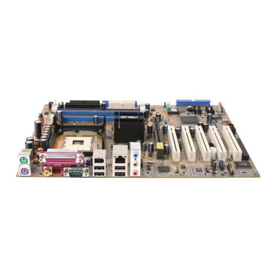
1.4.1 Major components The following are the major components of the P4C800-E Deluxe motherboard as pointed out in the picture on page 1-7. CPU socket 18. - Page 21 1615 ASUS P4C800-E Deluxe motherboard user guide...
-
Page 22: Core Specifications
1.4.2 Core specifications CPU socket. A 478-pin surface mount, Zero Insertion Force (ZIF) socket ® ® for the Intel Pentium 4 Processor, with 800/533/400 MHz system bus that allows 6.4GB/s, 4.3GB/s, and 3.2GB/s data transfer rates, respectively. The socket will support the Intel Prescott CPU when available. - Page 23 Speech controller. This Winbond speech controller supports the ASUS POST Reporter™ for configurable vocal POST alerts. RAID Ultra ATA133 connector. This connector supports two Ultra ATA133 HDDs. On RAID models, the HDDs on this connector may be configured as RAID0, RAID1, or RAID0+1 together with the Serial ATA HDDs on the SATA RAID connectors.
- Page 24 PCI slots. These five 32-bit PCI 2.2 expansion slots support bus master PCI cards like SCSI or LAN cards with 133MB/s maximum throughput. Audio CODEC. The AD1985 AC ‘97 2.3 stereo audio CODEC provides a 6-channel audio capability. The CODEC supports surround sound output, variable sample rate conversion, analog enumeration capability, and other major audio technologies for a complete integrated audio solution.
-
Page 25: Chapter 2: Hardware Information
Chapter 2 This chapter describes the hardware setup procedures that you have to perform when installing system components. It includes details on the switches, jumpers, and connectors on the motherboard. Hardware information... - Page 26 Chapter summary Motherboard installation ....... 2-1 Motherboard layouts ........2-2 Before you proceed ........2-3 Central Processing Unit (CPU) ..... 2-4 System memory ........... 2-10 Expansion slots ........... 2-14 Jumpers ............2-19 Connectors ........... 2-21 ASUS P4C800-E Deluxe motherboard...
-
Page 27: Motherboard Installation
Place nine (9) screws into the holes indicated by circles to secure the motherboard to the chassis. Do not overtighten the screws! Doing so may damage the motherboard. Place this side towards the rear of the chassis ASUS P4C800-E Deluxe motherboard user guide... -
Page 28: Motherboard Layout
Motherboard layout 24.5cm (9.6in) KBPWR PS/2KBMS T: Mouse B: Keyboard CR2032 3V Lithium Cell CMOS Power ATX12V SPDIF_O CPU_FAN COM1 PWR_FAN USBPW12 Bottom: Top: USB2 1394 USB1 USBPW34 USB2.0 Top: T: USB4 RJ-45 Intel 875P B: USB3 Memory Top:Line In Controller Center:Line Out Hub (MCH) -
Page 29: Before You Proceed
® SB_PWR P4C800-E Standby Powered P4C800-E Onboard LED Power ASUS P4C800-E Deluxe motherboard user guide... -
Page 30: Central Processing Unit (Cpu)
Central Processing Unit (CPU) 2.4.1 Overview The motherboard comes with a surface mount 478-pin Zero Insertion Force (ZIF) socket. The socket is designed for the Intel ® Pentium ® Processor in the 478-pin package with 512KB L2 cache. The Pentium 4 ®... -
Page 31: Installing The Cpu
90°-100° angle. Socket Lever 90 - 100 Make sure that the socket lever is lifted up to 90°-100° angle, otherwise the CPU does not fit in completely. ASUS P4C800-E Deluxe motherboard user guide... - Page 32 3. Position the CPU above the Gold Mark socket such that its marked corner matches the base of the socket lever. 4. Carefully insert the CPU into the socket until it fits in place. The CPU fits only in one correct orientation. DO NOT force the CPU into the socket to prevent bending the pins and damaging the CPU! 5.
-
Page 33: Installing The Heatsink And Fan
Your boxed Intel Pentium 4 Processor package should come with installation instructions for the CPU, heatsink, and the retention mechanism. If the instructions in this section do not match the CPU documentation, follow the latter. ASUS P4C800-E Deluxe motherboard user guide... - Page 34 2. Position the fan with the retention mechanism on top of the heatsink. Align and snap the four hooks of the retention mechanism to the holes on each corner of the module base. Make sure that the fan and retention mechanism assembly perfectly fits the heatsink and module base, otherwise you cannot snap the hooks into the holes.
-
Page 35: Connecting The Cpu Fan Cable
CPU fan cable to the connector on the motherboard labeled CPU_FAN. CPU Fan Connector (CPU_FAN) Don’t forget to connect the CPU fan connector! Hardware monitoring errors may occur if you fail to plug this connector. ASUS P4C800-E Deluxe motherboard user guide... -
Page 36: System Memory
System memory 2.5.1 Overview The motherboard comes with four Double Data Rate (DDR) Dual Inline Memory Module (DIMM) sockets. These sockets support up to 4GB system memory using 184-pin unbuffered ECC or non-ECC PC3200/ PC2700/PC2100 DDR DIMMs, and allow up to 6.4GB/s data transfer rate. The following figure illustrates the location of the DDR DIMM sockets. - Page 37 800 MHz PC3200/PC2700*/PC2100 400/333*/266 MHz 533 MHz PC2700/PC2100 333/266 MHz 400 MHz PC2100 266 MHz *When using 800MHz CPU FSB, PC2700 DDR DIMMs may run only at 320MHz (not 333MHz) due to chipset limitation. ASUS P4C800-E Deluxe motherboard user guide 2-11...
- Page 38 AG32L64T8SQC4S Samsung K4H560838D-TCC4 512MB AG64L64T8SQC4S Samsung K4H560838D-TCC4 512MB TAKEMS MS64D64020U-5 TAKEMS MS25D25680S-5 256MB X4W560840A-40 Obtain DDR DIMMs only from ASUS qualified vendors for better system performance. Visit the ASUS website (www.asus.com) for the latest QVL. 2-12 Chapter 2: Hardware information...
-
Page 39: Installing A Dimm
DIMM. Support the DIMM lightly with your fingers when pressing the retaining clips. The DIMM might get damaged when it flips out with extra force. 2. Remove the DIMM from the socket. ASUS P4C800-E Deluxe motherboard user guide 2-13... -
Page 40: Expansion Slots
Expansion slots In the future, you may need to install expansion cards. The motherboard has five PCI slots, one Accelerated Graphics Port (AGP) Pro slot, and a Wi-Fi slot. The following sub-sections describe the slots and the expansion cards that they support. Make sure to unplug the power cord before adding or removing expansion cards. -
Page 41: Standard Interrupt Assignments
When using PCI cards on shared slots, ensure that the drivers support “Share IRQ” or that the cards do not need IRQ assignments. Otherwise, conflicts will arise between the two PCI groups, making the system unstable and the card inoperable. ASUS P4C800-E Deluxe motherboard user guide 2-15... -
Page 42: Pci Slots
2.6.3 PCI slots There are five 32-bit PCI slots on this motherboard. The slots support PCI cards such as a LAN card, SCSI card, USB card, and other cards that comply with PCI specifications. 1. The PCI 5 slot and the Wi-Fi slot may not be used at the same time. 2. -
Page 43: Agp Pro Slot
Keyed for 1.5v P4C800-E Accelerated Graphics Port (AGP) If installing the ATi 9500 or 9700 Pro Series VGA cards, use only the card version PN xxx-xxxxx-30 or later, for optimum performance and overclocking stability. ASUS P4C800-E Deluxe motherboard user guide 2-17... -
Page 44: Wi-Fi Slot
2.6.5 Wi-Fi slot The Wi-Fi (Wireless Fidelity) slot will support the ASUS Wi-Fi module when available. Visit the ASUS website (www.asus.com) for product updates. The Wi-Fi slot conforms to the Institute of Electrical and Electronics Engineers (IEEE) 802.11b standard for wireless devices operating in the 2.4 GHz frequency band. -
Page 45: Jumpers
4. Hold down the <Del> key during the boot process and enter BIOS setup to re-enter data. Except when clearing the RTC RAM, never remove the cap on CLRTC jumper default position. Removing the cap will cause system boot failure! ASUS P4C800-E Deluxe motherboard user guide 2-19... - Page 46 CLRTC ® P4C800-E Normal Clear CMOS (Default) P4C800-E Clear RTC RAM You do not need to clear the RTC when the system hangs due to overclocking. For system failure due to overclocking, use the C.P.R. (CPU Parameter Recall) feature. Shut down and reboot the system so BIOS can automatically reset parameter settings to default values.
-
Page 47: Connectors
(Pin 5 is removed to prevent incorrect insertion when using ribbon cables with pin 5 plug). FLOPPY PIN 1 NOTE: Orient the red markings on ® the floppy ribbon cable to PIN 1. P4C800-E P4C800-E Floppy Disk Drive Connector ASUS P4C800-E Deluxe motherboard user guide 2-21... - Page 48 2. IDE connectors (40-1 pin PRI_IDE[blue], SEC_IDE [black) This connector supports the provided UltraDMA/100/66 IDE hard disk ribbon cable. Connect the cable’s blue connector to the primary (recommended) or secondary IDE connector, then connect the gray connector to the UltraDMA/100/66 slave device (hard disk drive) and the black connector to the UltraDMA/100/66 master device.
- Page 49 ICHR chipset support to one of the IDE channels (either primary or secondary channel). 2. The Serial ATA RAID feature (RAID 0) is available only if you are using Windows XP. ASUS P4C800-E Deluxe motherboard user guide 2-23...
- Page 50 Parallel ATA and Serial ATA device configurations Following are the Parallel ATA and Serial ATA device configurations supported by Intel ICH5 specifications. Native operating systems (OS) are Windows 2000/XP. ICH5 supports a maximum of six (6) devices using these OS. Legacy OS are MS-DOS, Windows 98/Me/NT4.0.
- Page 51 SATARaid™ utility and SATA BIOS setup during POST if there are no connected Serial ATA devices. 2. The Promise PDC20376 RAID controller does not support ATAPI devices such as CD-ROMs, DVD-ROMs, etc. ASUS P4C800-E Deluxe motherboard user guide 2-25...
- Page 52 5. RAID ATA/133/100/66/33 connector (40-1 pin PRI_RAID) (on RAID models only) This connector supports either RAID 0 or RAID 1 configuration through ® the onboard Promise PDC20378 controller. You can connect two UltraATA133 hard disks to this connector and set up a disk array configuration.
- Page 53 These are not jumpers! DO NOT place jumper caps on the fan connectors! PWR_FAN CPU_FAN Rotation +12V ® CHA_FAN P4C800-E +12V Rotation P4C800-E 12-Volt Fan Connectors ASUS P4C800-E Deluxe motherboard user guide 2-27...
- Page 54 9. ATX power connectors (20-pin ATXPWR, 4-pin ATX12V) These connectors connect to an ATX 12V power supply. The plugs from the power supply are designed to fit these connectors in only one orientation. Find the proper orientation and push down firmly until the connectors completely fit.
- Page 55 GAME/MIDI cable to this connector. The GAME/MIDI port on the module connects a joystick or a game pad for playing games, and MIDI devices for playing or editing audio files. ® P4C800-E GAME P4C800-E Game Connector ASUS P4C800-E Deluxe motherboard user guide 2-29...
- Page 56 13. USB headers (10-1 pin USB56, USB78) If the USB ports on the rear panel are inadequate, two USB headers are available for additional USB ports. The USB header complies with USB 2.0 specification that supports up to 480 Mbps connection speed. This speed advantage over the conventional 12 Mbps on USB 1.1 allows faster Internet connection, interactive gaming, and simultaneous running of high-speed peripherals.
- Page 57 1394 cable plug from the module to this connector. You may also connect a 1394-compliant internal hard disk to this connector. ® P4C800-E IE1394_2 P4C800-E IEEE-1394 Connector NEVER connect a USB cable to the IEEE 1394 connector. Doing so will damage the motherboard! ASUS P4C800-E Deluxe motherboard user guide 2-31...
- Page 58 16. Front panel audio connector (10-1 pin FP_AUDIO) This is an interface for the Intel front panel audio cable that allow convenient connection and control of audio devices. By default, the pins labeled LINE OUT_R/BLINE_OUT_R and the pins LINE OUT_L/BLINE_OUT_L are shorted with jumper caps. Remove the caps only when you are connecting the front panel audio cable.
- Page 59 Pressing the power switch while in the ON mode for more than 4 seconds turns the system OFF. • Reset Switch Lead (2-pin RESET) This 2-pin connector connects to the case-mounted reset switch for rebooting the system without turning off the system power. ASUS P4C800-E Deluxe motherboard user guide 2-33...
- Page 60 2-34 Chapter 2: Hardware information...
-
Page 61: Chapter 3: Powering Up
Chapter 3 This chapter describes the power up sequence and gives information on the BIOS beep codes. Powering up... - Page 62 Chapter summary Starting up for the first time ......3-1 Vocal POST Messages ........3-2 Powering off the computer ......3-4 ASUS P4C800-E Deluxe motherboard...
-
Page 63: Starting Up For The First Time
Motherboard timer not operational Keyboard controller BAT test error General exception error Display memory error CMOS shutdown register read/write error 7. At power on, hold down <Delete> to enter BIOS Setup. Follow the instructions in Chapter 4. ASUS P4C800-E Deluxe motherboard user guide... -
Page 64: Vocal Post Messages
Vocal POST Messages This motherboard includes the Winbond speech controller to support a special feature called the ASUS POST Reporter™. This feature gives you vocal POST messages and alerts to inform you of system events and boot status. In case of a boot failure, you will hear the specific cause of the problem. - Page 65 • Call ASUS technical support for assistance. See the “ASUS contact information” on page x. System completed Power-On Self Test • No action required Computer now booting from operating • No action required system ASUS P4C800-E Deluxe motherboard user guide...
-
Page 66: Powering Off The Computer
Powering off the computer You must first exit the operating system and shut down the system before switching off the power. For ATX power supplies, you can press the ATX power switch after exiting or shutting down the operating system. The message “You can now safely turn off your computer”... -
Page 67: Chapter 4: Bios Setup
Chapter 4 This chapter tells how to change system settings through the BIOS Setup menus. Detailed descriptions of the BIOS parameters are also provided. BIOS setup... - Page 68 Chapter summary Managing and updating your BIOS ....4-1 BIOS Setup program ........4-6 Main menu ............4-9 Advanced menu ........... 4-14 Power menu ..........4-27 Boot menu ............ 4-32 Exit menu ............4-38 ASUS P4C800-E Deluxe motherboard...
-
Page 69: Managing And Updating Your Bios
4.1.2 Using AFUDOS to update the BIOS Update the BIOS using the AFUDOS.EXE utility in DOS environment. 1. Visit the ASUS website (www.asus.com) to download the latest BIOS file for your motherboard. Save the BIOS file to a bootable floppy disk. - Page 70 4. At the DOS prompt, type the command line: afudos / i<filename.rom> where “filename.rom” means the latest (or original) BIOS file that you copied to the bootable floppy disk. The screen displays the status of the update process. The BIOS information on the screen is for reference only. What you see on your screen may not be exactly the same as shown.
-
Page 71: Using Asus Ez Flash To Update The Bios
4.1.3 Using ASUS EZ Flash to update the BIOS The ASUS EZ Flash feature allows you to easily update the BIOS without having to go through the long process of booting from a diskette and using a DOS-based utility. The EZ Flash is built-in the BIOS firmware so it is accessible by simply pressing <Alt>... -
Page 72: Recovering The Bios With Crashfree Bios 2
3. Insert a floppy disk that contains the original, or the latest, BIOS file for this motherboard (P4C800ED.ROM). If the BIOS file that you downloaded from the ASUS website has a different filename (e.g. P4C800ED11.ROM), rename it to P4C800ED.ROM. The BIOS update process continues when the P4C800ED.ROM is found. - Page 73 4. When the BIOS update process is complete, reboot the system. The recovered BIOS may not be the latest BIOS version for this motherboard. Visit the ASUS website (www.asus.com) to download the latest BIOS file. ASUS P4C800-E Deluxe motherboard user guide...
-
Page 74: Bios Setup Program
The BIOS setup screens shown in this chapter are for reference purposes only, and may not exactly match what you see on your screen. Visit the ASUS website (www.asus.com) to download the latest product and BIOS information. Chapter 4: BIOS Setup... -
Page 75: Bios Menu Screen
At the bottom right corner of a menu screen are the navigation keys for that particular menu. Use the navigation keys to select items in the menu and change the settings. Some of the navigation keys differ from one screen to another. ASUS P4C800-E Deluxe motherboard user guide... -
Page 76: Menu Items
Language [English] Use [+] or [-] to Primary IDE Master :[ST320413A] configure system time. Primary IDE Slave :[ASUS CD-S340] For example, selecting Main shows the Secondary IDE Master :[Not Detected] Secondary IDE Slave :[Not Detected] Third IDE Master :[Not Detected]... -
Page 77: Main Menu
[360K, 5.25 in.] [1.2M , 5.25 in.] [720K , 3.5 in.] [1.44M, 3.5 in.] [2.88M, 3.5 in.] 4.3.4 Language [English] This field allows you to choose the BIOS language version from the available options. ASUS P4C800-E Deluxe motherboard user guide... -
Page 78: Primary And Secondary Ide Master/Slave
4.3.5 Primary and Secondary IDE Master/Slave While entering Setup, BIOS auto-detects the presence of IDE devices. There is a separate sub-menu for each IDE device. Select a device item then press Enter to display the IDE device information. Primary IDE Master Select the type Device : Hard Disk... -
Page 79: Ide Configuration
(OS) that you installed. Set to Enhanced Mode if you are using native OS, such as Windows 2000/XP. Set to Compatible Mode if you are using legacy OS including MS-DOS, Windows ME/98/NT4.0. Configuration options: [Compatible Mode] [Enhanced Mode] ASUS P4C800-E Deluxe motherboard user guide 4-11... - Page 80 Refer to the section “Parallel ATA and Serial ATA device configurations” on page 2-24 for the appropriate settings of the IDE Configuration items under different operating systems. Enhanced Mode Support On [S-ATA] The default setting S-ATA allows you to use native OS on Serial ATA and Parallel ATA ports.
-
Page 81: System Information
Change Option General Help Save and Exit Exit AMI BIOS This item displays the auto-detected BIOS information. Processor This item displays the auto-detected CPU specification. System Memory This item displays the auto-detected system memory. ASUS P4C800-E Deluxe motherboard user guide 4-13... -
Page 82: Advanced Menu
Advanced menu The Advanced menu items allow you to change the settings for the CPU and other system devices. Take caution when changing the settings of the Advanced menu items. Incorrect field values may cause the system to malfunction. JumperFree Configuration Configure CPU. - Page 83 CPU speed. The value of this item is auto-detected by BIOS. The values range from 100 to 400. DRAM Frequency [Auto] Allows you to set the DDR operating frequency. Configuration options: [266 MHz] [333 MHz] [400 MHz] [Auto] ASUS P4C800-E Deluxe motherboard user guide 4-15...
- Page 84 AGP/PCI Frequency (MHz) [Auto] Allows you to adjust to a higher AGP/PCI frequency for better system performance and overclocking capability. Configuration options: [Auto] [66.66/33.33] [72.73/36.36] [80.00/40.00] Selecting a very high AGP/PCI frequency may cause the system to become unstable! If this happens, revert to the default setting. CPU VCore Voltage [Auto] Allows you to select a specific CPU VCore voltage.
-
Page 85: Cpu Configuration
This item allows you to enable or disable the processor Hyper-Threading Technology. Configuration options: [Disabled] [Enabled] The item Hyper-Threading Technology appears only if you installed an Intel Pentium 4 CPU that supports this feature. ASUS P4C800-E Deluxe motherboard user guide 4-17... -
Page 86: Chipset
4.4.3 Chipset The Chipset menu items allow you to change the advanced chipset settings. Select an item then press Enter to display the sub-menu. Advanced Chipset settings WARNING: Setting wrong values in the sections below may cause system to malfunction. Configure DRAM Timing by SPD [Enabled] Performance Acceleration Mode... - Page 87 Allows you to select the size of mapped memory for AGP graphic data. Configuration options: [4MB] [8MB] [16MB] [32MB] [64MB] [128MB] [256MB] Spread Spectrum [Enabled] Configuration options: [Disabled] [Enabled] ICH Delayed Transaction [Enabled] Configuration options: [Disabled] [Enabled] MPS Revision [1.4] Configuration options: [1.1] [1.4] ASUS P4C800-E Deluxe motherboard user guide 4-19...
-
Page 88: Onboard Devices Configuration
4.4.4 Onboard Devices Configuration OnBoard AC’97 Audio [Auto] OnBoard Promise Controller [Enabled] Operating Mode [RAID] OnBoard IEEE 1394 Controller [Enabled] OnBoard LAN [Enabled] OnBoard LAN Boot ROM [Disabled] Serial Port1 Address [3F8/IRQ4] Serial Port2 Address [2F8/IRQ3] Parallel Port Address [378] Parallel Port Mode [Normal] EPP Version... - Page 89 Allows you to select the Parallel Port IRQ. Configuration options: [IRQ5] [IRQ7] Onboard Game/MIDI Port [Disabled] Allows you to select the Game Port address or to disable the port. Configuration options: [Disabled] [200/300] [200/330] [208/300] [208/330] ASUS P4C800-E Deluxe motherboard user guide 4-21...
-
Page 90: Pci Pnp
4.4.5 PCI PnP The PCI PnP menu items allow you to change the advanced settings for PCI/PnP devices. The menu includes setting IRQ and DMA channel resources for either PCI/PnP or legacy ISA devices, and setting the memory size block for legacy ISA devices. Take caution when changing the settings of the PCI PnP menu items. -
Page 91: Usb Configuration
If no USB device is detected, the item shows None. USB Function [8 USB Ports] Allows you to set the number of USB ports to activate. Configuration options: [Disabled] [2 USB Ports] [4 USB Ports] [6 USB Ports] [8 USB Ports] ASUS P4C800-E Deluxe motherboard user guide 4-23... -
Page 92: Usb Mass Storage Device Configuration
Legacy USB Support [Auto] Allows you to enable or disable support for legacy USB devices. Setting to Auto allows the system to detect the presence of USB devices at startup. If detected, the USB controller legacy mode is enabled. If no USB device is detected, the legacy USB support is disabled. -
Page 93: Speech Configuration
General Help Save and Exit Exit Speech POST Reporter [Enabled] Allows you to enable or disable the ASUS Speech POST Reporter™ feature. Configuration options: [Disabled] [Enabled] The following items appear only when Speech POST Reporter is set to Enabled. Report IDE Error [Disabled]... -
Page 94: Instant Music Configuration
4.4.8 Instant Music Configuration Instant Music Option Disable/Enable Instant Music feature. Instant Music [Disabled] Select Screen Select Item Change Option General Help Save and Exit Exit Instant Music [Disabled] Allows you to enable or disable the Instant Music feature in BIOS. Configuration options: [Disabled] [Enabled] When Instant Music is enabled, the PS/2 keyboard power up feature is automatically disabled. -
Page 95: Power Menu
Configuration options: [Disabled] [Enabled] 4.5.5 BIOS -> AML ACPI Table [Enabled] Allows you to enable or disable the inclusion of the BIOS ->AML exchange pointer to (X)RSDT pointer list. Configuration options: [Disabled] [Enabled] ASUS P4C800-E Deluxe motherboard user guide 4-27... -
Page 96: Apm Configuration
4.5.6 APM Configuration APM Configuration Enabled or disable APM. Power Management/APM [Enabled] Video Power Down Mode [Suspend] Hard Disk Power Down Mode [Suspend] Suspend Time Out [Disabled] Throttle Slow Clock Ratio [50%] System Thermal [Disabled] Power Button Mode [On/Off] Restore on AC Power Loss [Power Off] Select Screen Power On By RTC Alarm... - Page 97 This parameter allows you to use specific keys on the keyboard to turn on the system. This feature requires an ATX power supply that provides at least 1A on the +5VSB lead. Configuration options: [Disabled] [Enabled] ASUS P4C800-E Deluxe motherboard user guide 4-29...
-
Page 98: Hardware Monitor
Q-Fan Control [Disabled] This item allows you to enable or disable the ASUS Q-Fan feature that smartly adjusts the fan speeds for more efficient system operation. When this field is set to [Enabled], the... - Page 99 If any of the monitored items is out of range, the following error message appears: “Hardware Monitor found an error. Enter Power setup menu for details”. You will then be prompted to “Press F1 to continue or DEL to enter SETUP”. ASUS P4C800-E Deluxe motherboard user guide 4-31...
-
Page 100: Boot Menu
Specifies the boot sequence from the 1st Boot Device [First Floppy Drive] available devices. 2nd Boot Device [PM-ST320413A] 3rd Boot Device [PS-ASUS CD-S340] A device enclosed in parenthesis has been disabled in the corresponding type menu. Select Screen Select Item... -
Page 101: Boot Settings Configuration
Allows you to select the power-on state for the NumLock. Configuration options: [Off] [On] PS/2 Mouse Support [Auto] Allows you to enable or disable support for PS/2 mouse. Configuration options: [Disabled] [Enabled] [Auto] ASUS P4C800-E Deluxe motherboard user guide 4-33... - Page 102 Typematic Rate [Fast] Allows you to select the keyboard typematic rate. Configuration options: [Slow] [Fast] Boot to OS/2 [No] Allows you to specify the OS/2 compatibility mode. Configuration options: [No] [Yes] Wait for ‘F1’ If Error [Enabled] When set to Enabled, the system waits for F1 key to be pressed when error occurs.
-
Page 103: Security
To change the supervisor password, follow the same steps as in setting a user password. To clear the supervisor password, select the Change Supervisor Password then press Enter. The message “Password Uninstalled” appears. ASUS P4C800-E Deluxe motherboard user guide 4-35... - Page 104 If you forget your BIOS password, you can clear clear it by erasing the CMOS Real Time Clock (RTC) RAM. See section “2.7 Jumpers” for information on how to erase the RTC RAM. After you have set a supervisor password, the other items appear to allow you to change other security settings.
-
Page 105: Change User Password
Setup utility. When set to [Always], BIOS checks for user password both when accessing Setup and booting the system. Configuration options: [Setup] [Always] Boot Sector Virus Protection [Disabled] Allows you to enable or disable the boot sector virus protection. Configuration options: [Disabledc] [Enabled] ASUS P4C800-E Deluxe motherboard user guide 4-37... -
Page 106: Exit Menu
Exit menu The Exit menu items allow you to load the optimal or failsafe default values for the BIOS items, and save or discard your changes to the BIOS items. Exit Options Exit system setup after saving the Exit & Save Changes changes. -
Page 107: Discard Changes
Setup menus. When you select this option or if you press <F5>, a confirmation window appears. Select [Yes] to load default values. Select Exit Saving Changes or make other changes before saving the values to the non-volatile RAM. ASUS P4C800-E Deluxe motherboard user guide 4-39... - Page 108 4-40 Chapter 4: BIOS Setup...
-
Page 109: Chapter 5: Software Support
Chapter 5 This chapter describes the contents of the support CD that comes with the motherboard package. Software support... - Page 110 Chapter summary Install an operating system ......5-1 Support CD information ........ 5-1 Software information ........5-7 Promise RAID configurations ..... 5-25 Intel RAID for Serial ATA ......5-33 ASUS P4C800-E Deluxe motherboard...
-
Page 111: Install An Operating System
The contents of the support CD are subject to change at any time without notice. Visit the ASUS website for updates. 5.2.1 Running the support CD To begin using the support CD, simply insert the CD into your CD-ROM drive. -
Page 112: Drivers Menu
5.2.2 Drivers menu The drivers menu shows the available device drivers if the system detects installed devices. Install the necessary drivers to activate the devices. Intel Chipset Inf Update program ® This item installs the Intel Chipset INF Update Program that enables Plug-n-Play INF support for Intel chipset components. -
Page 113: Utilities Menu
This program allows you to download the latest version of the BIOS from the ASUS website. Installing ASUS Update also installs ASUS MyLogo2. Before using the ASUS Update, make sure that you have an Internet connection so you can connect to the ASUS website. -
Page 114: Asus Contact Information
FastTrak Mirrored (RAID 1) or Striped/Mirrored (RAID 0/1) disk array. Winbond Voice Editor This program is for recording and customizing wave files for the ASUS POST Reporter™. Use this program if you wish to change the default vocal POST messages. See section “3.2 Vocal POST messages” for a list of the default messages. -
Page 115: Other Information
CD. Click an icon to display the specified information. Motherboard Info The window displays the general specifications of the motherboard. Browse this CD The window displays the support CD contents in graphical format. ASUS P4C800-E Deluxe motherboard user guide... - Page 116 Technical Support Form The window displays the ASUS Technical Support Request Form that you have to fill up when requesting technical support. Filelist The window displays the contents of the support CD and a brief description of each in text format.
-
Page 117: Software Information
This section provides details on the software applications that the motherboard supports. 5.3.1 ASUS Update The ASUS Update is a utility that allows you to update the motherboard BIOS. This utility requires an Internet connection either through a network or an Internet Service Provider (ISP). -
Page 118: Asus Mylogo2
5.3.2 ASUS MyLogo2™ The ASUS MyLogo2™ is automatically installed when you install the ASUS Update utility from the support CD. See section “5.2.3 Utilities menu”. Before using ASUS MyLogo2 feature, use the AFUDOS utility to make a copy of your original BIOS file, or obtain the latest BIOS version from the ASUS website. - Page 119 Your system boots with the new boot logo. Instead of starting from ASUS Update, you may also launch ASUS MyLogo2 directly from the Windows Start menu to change your BIOS boot logo. After you have modified the BIOS file with the new logo, use the ASUS Update utility to upload the new BIOS.
-
Page 120: Asus Pc Probe
5.3.3 ASUS PC Probe The ASUS PC Probe is a convenient utility to continuously monitor the vital system information, such as fan rotations, voltages, and temperatures. This utility also allows you to check other information about your computer, including hard disk space, memory usage, and CPU type, CPU speed, and internal/external frequencies through the DMI Explorer. - Page 121 Fan Monitor Shows the PC fan rotation. Fan Warning threshold adjustment (Move the slider up to increase the threshold level or down to decrease the threshold level) Voltage Monitor Shows the PC voltages. ASUS P4C800-E Deluxe motherboard user guide 5-11...
- Page 122 Settings Lets you set threshold levels and polling intervals or refresh times of the PC’s temperature, fan rotation, and voltages. CPU Cooling System Setup Lets you select when to enable software CPU cooling. When When CPU Overheated is selected, the CPU cooling system is enabled whenever the CPU temperature reaches the threshold value.
- Page 123 PC, such as CPU type, CPU speed, and internal/external frequencies, and memory size. Utility Lets you run programs outside of the ASUS Probe modules. To run a program, click Execute Program NOTE: This feature is currently unavailable. ASUS P4C800-E Deluxe motherboard user guide...
- Page 124 ASUS PC Probe Task Bar Icon Right clicking the PC Probe icon brings up a menu to open or exit ASUS PC Probe and pause or resume all system monitoring. When the ASUS PC Probe senses a problem with your PC,...
-
Page 125: Winbond Voice Editor
Playing the default wave files To play the default wave files, simply click on a POST event on the left side of the screen, then click the Play button. The default language setting is English. ASUS P4C800-E Deluxe motherboard user guide 5-15... - Page 126 Changing the default language 1. Click on the Load button. a window showing the available languages appears. 2. Select your desired language then click Open. The event messages for the language you selected appear on the Voice Editor screen. For some languages, not all events have a corresponding message due to file size constraints.
- Page 127 5. From the Voice Editor screen, click on the Add button to display the Add Wave File window. 6. Copy the wave files that you recorded to the database. Close the window when done. ASUS P4C800-E Deluxe motherboard user guide 5-17...
- Page 128 7. Click a POST event on the Voice Editor screen, then on the Edit button. The Event Sound Editor window appears. 8. Locate and select your wave file for the event then click on the arrow opposite Voice1. The file you selected appears on the space next to it.
-
Page 129: Soundmax ® 4 Xl Software
If the SoundMAX4 XL software is correctly installed, you will find the SoundMAX4 XL icon on the taskbar. SoundMAX4 XL icon From the taskbar, double-click on the SoundMAX4 XL icon to display the SoundMAX Control Panel. ASUS P4C800-E Deluxe motherboard user guide 5-19... -
Page 130: Setup Wizards
Setup wizards Use the speaker and microphone setup wizards to fine tune the gain/ attenuation of the inputs/outputs for optimal audio performance. You may launch the setup wizards by clicking the Configuration button when AudioESP detects and verifies a newly connected peripheral, or by clicking on the icon from the SoundMAX control panel. -
Page 131: Listening Environment Options
The Preferences page of the SoundMAX4 XL allows you to change various audio settings. Listening environment options The SoundMAX4 XL support several audio technologies including SoundMAX SPX™ Animated Audio, 3DPA™, MultiDrive™ 5.1, EnvironmentFC™, MacroFX/ZoomFX™, and Virtual Theater Surround. ASUS P4C800-E Deluxe motherboard user guide 5-21... -
Page 132: Asus Instant Music
2. Instant Music does not work if you installed and enabled an add-on sound card. 3. Instant Music only supports PS/2 keyboard. To enable ASUS Instant Music: 1. Connect the analog audio cable from the optical drive (CD-ROM, DVD- ROM, or CD-RW drive) to the 4-pin CD-In connector (labeled CD) on the motherboard. - Page 133 VOL. DOWN VOL. UP ON/OFF To guide you in using Instant Music, place the Instant Music label over the function keys on the keyboard. The Instant Music keyboard label comes with your motherboard package. ASUS P4C800-E Deluxe motherboard user guide 5-23...
- Page 134 Instant Music function keys (Set 2) CAPS SCROLL LOCK LOCK CD ON/OFF STOP/EJECT PLAY/PAUSE PREVIOUS NEXT VOL. DOWN VOL. UP 3. Connect speakers or a headphone to the Line Out (lime colored) port on the rear panel for audio output. You may also connect a headphone to the headphone jack on the CD-ROM drive front panel.
-
Page 135: Promise Raid Configurations
CD to a floppy disk before creating RAID configurations. 2. Refer to the FastTrak 378 Quick Start Guide and SATA Quick Start Guide in the support CD for detailed information on RAID configurations under different operating systems. ASUS P4C800-E Deluxe motherboard user guide 5-25... -
Page 136: Install The Hard Disks
5.4.1 Install the hard disks The PDC20378 chipset supports Ultra ATA/133/100/66 hard disk drives. For optimal performance, install identical drives of the same model and capacity when creating a disk array. • If you are creating a RAID 0 (striping) array for perfomance, use two new drives. - Page 137 Delete Array ..[ 4 ] [ 4 ] Rebuild Array..[ 5 ] [ 5 ] [ Keys Available ] Press 1..5 to select Option [ESC] Exit ASUS P4C800-E Deluxe motherboard user guide 5-27...
- Page 138 5.4.3 Creating a RAID 0 array (Performance) 1. In the FastBuild™ utility main menu, press “1” to select Auto Setup. The following screen appears. FastBuild (tm) Utility 2.00 (c) 2002-2005 Promise Technology, Inc. [ Auto Setup Options Menu ] Optimize Array for: Performance [ Array Setup Configuration ] Mode ........
- Page 139 Security array has been created. Array has been created. <Press any key to reboot> 6. Press any key to reboot the system. During the boot process, the MBFastTrak376 BIOS checks and displays the disk array information. ASUS P4C800-E Deluxe motherboard user guide 5-29...
- Page 140 7. Use the FDISK utility and follow the format procedure for installing a new hard drive. After you have formatted the arrayed drives, install an operating system (OS). 8. Install the RAID driver from the support CD that came with the motherboard package.
-
Page 141: Other Fastbuild Utility Commands
4. Power off the system and replace the hard disk with an identical model. 5. Reboot and enter the FastBuild™ Main Menu again. 6. Select <5> for Rebuild Array. The malfunctioning array is highlighted. Press Enter to select. ASUS P4C800-E Deluxe motherboard user guide 5-31... - Page 142 FastBuild (tm) Utility 2.00 (c) 2002-2005 Promise Technology, Inc. [ Rebuild Array Menu ] Array No RAID Mode Total Drv Capacity Status Array Mirror/Stripe 7999 Critical Array ----- ----- ----- ----- Array ----- ----- ----- ----- Array ----- ----- ----- ----- [ Keys Available ] [ ] Up...
-
Page 143: Intel Raid For Serial Ata
4. Press <F10> to save your changes and exit the Setup utility. For more information on the Intel RAID for Serial ATA , refer to the Intel Application Accelerator (RAID Edition) User’s Manual in the motherboard support CD. See path \Manual\IAA RAID Manual.doc. ASUS P4C800-E Deluxe motherboard user guide 5-33... -
Page 144: Installing Serial Ata Hard Disks
5.5.2 Installing Serial ATA hard disks 1. A Serial ATA hard disk requires SATA data (4-conductor) and power cables. Make sure that you have the appropriate SATA cables before your proceed with the installation. 2. Carefully follow other hard disk installation instructions that came with the Serial ATA hard disks. -
Page 145: Creating A Raid Volume
Are you sure you want to create this volume (Y/N) 5. Scroll down to option 4. Exit and press <Enter> to exit the RAID configuration utility. Press Y when a confirmation message appears. ASUS P4C800-E Deluxe motherboard user guide 5-35... -
Page 146: Deleting A Raid Volume
5.5.5 Deleting a RAID Volume Take caution when deleting a RAID volume. Deleting a RAID volume erases all data on the RAID drives! Intel(R) Integrated RAID for Serial ATA - RAID Configuration Utility Copyright(C) 2003 Intel Corporation. All Rights Reserved. v3.x.x.xxxx DELETE ARRAY MENU Name Level... - Page 147 RAID volume. WARNING: Selecting "Yes" will cause all data on any RAID disk (RAID Volume or Other RAID Disk) to be lost. Are you sure you want to destroy all RAID data (Y/N): ASUS P4C800-E Deluxe motherboard user guide 5-37...
- Page 148 5-38 Chapter 5: Software support...
- Page 149 P4C800-E Refer to the Quick Setup Guide when installing components or devices for the items indicated in this reference card. CPU_FAN PWR_FAN ® Speaker Connector Power LED CHA_FAN P4C800-E Reset SW IDE_LED PANEL ATX Power SMI Lead Switch* Requires an ATX power supply.
Need help?
Do you have a question about the P4C800-E Deluxe and is the answer not in the manual?
Questions and answers