Table of Contents
Advertisement
Quick Links
25589 Highway 1
McBee, SC 29101
WARNING: If the information in these
instructions is not followed exactly, a fire
or explosion may result causing property
damage, personal injury or death.
Do not store or use gasoline or other
flammable vapors and liquids in the
vicinity of this or any other appliance.
WHAT TO DO IF YOU SMELL GAS:
•
Do not try to light any appliance.
•
Do not touch any electrical switch; do
not use any phone in your building.
•
Immediately call your gas supplier
from a neighbor's phone. Follow the
gas supplier's instructions.
•
If you cannot reach your gas supplier,
call the fire department.
Installation
performed by a
service agency or the gas supplier.
Thank you for buying this energy efficient boiler.
We appreciate your confidence in our products.
PRINTED IN THE U.S.A. 0711
and
service
must
qualified
installer,
MAINTENANCE - LIMITED WARRANTY
be
Instruction Manual
XP BOILER
MODELS: XB/XW
1000, 1300, 1700
2000, 2600, 3400
SERIES 100/101
INSTALLATION - OPERATION -
320741-002
Advertisement
Table of Contents

Related Manuals for A.O. Smith XB-1000


Summary of Contents for A.O. Smith XB-1000
- Page 1 Instruction Manual XP BOILER MODELS: XB/XW 1000, 1300, 1700 2000, 2600, 3400 SERIES 100/101 INSTALLATION - OPERATION - 25589 Highway 1 MAINTENANCE - LIMITED WARRANTY McBee, SC 29101 WARNING: If the information in these instructions is not followed exactly, a fire or explosion may result causing property damage, personal injury or death.
-
Page 2: Table Of Contents
TABLE OF CONTENTS TABLE OF CONTENTS ................2 SAFE INSTALLATION, USE AND SERVICE.......... 3 GENERAL SAFETY................4 INTRODUCTION ..................5 Model Identification ................5 Abbreviations Used ................5 Qualifications ..................5 DIMENSIONS AND CAPACITY DATA ............ 6 FEATURES AND COMPONENTS ............10 Component Description .............. -
Page 3: Safe Installation, Use And Service
SAFE INSTALLATION, USE AND SERVICE The proper installation, use and servicing of this boiler is extremely important to your safety and the safety of others. Many safety-related messages and instructions have been provided in this manual and on your boiler to warn you and others of a potential injury hazard. -
Page 4: General Safety
GENERAL SAFETY GROUNDING INSTRUCTIONS HIGH ALTITUDE INSTALLATIONS This boiler must be grounded in accordance with the National Electrical Code, Canadian Electrical Code and/or local codes. Boiler is polarity sensitive; correct wiring is imperative for proper operation. This boiler must be connected to a grounded metal, permanent wiring system, or an equipment grounding conductor must be run with the circuit conductors and connected to the equipment grounding terminal or lead on the boiler. -
Page 5: Introduction
INTRODUCTION QUALIFICATIONS This Instruction Manual covers XP Boiler models XB/XW 1000, 1300, 1700, 2000, 2600, 3400 - Series 100/101. The instructions QUALIFIED INSTALLER OR SERVICE AGENCY and illustrations contained in this Instruction manual will provide you with troubleshooting procedures to diagnose and repair Installation and service of this boiler requires ability equivalent common problems and verify proper operation. -
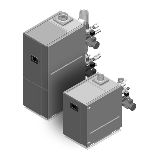
Page 6: Dimensions And Capacity Data
DIMENSIONS AND CAPACITY DATA FIGURE 1. SINGLE HEAT EXCHANGER BOILER TABLE 1. ROUGH IN DIMENSIONS (SINGLE) Models XB/XW-1000 XB/XW-1300 XB/XW-1700 Dimensions inches inches inches Flue Outlet Diameter Air Intake Diameter Water Inlet 2 inch NPT 2 1/2 inch NPT Water Outlet 2 inch NPT 2 1/2 inch NPT Gas Inlet... - Page 7 FIGURE 2. DOUBLE HEAT EXCHANGER BOILER TABLE 3. ROUGH IN DIMENSIONS (DOUBLE) Models XB/XW-2000 XB/XW-2600 XB/XW-3400 Dimensions inches inches inches Flue Outlet Diameter Air Intake Diameter Water Inlet 3 inch NPT 4 inch NPT Water Outlet 3 inch NPT 4 inch NPT Gas Inlet 2 inch NPT 3 inch NPT...
- Page 8 RATINGS TABLE 5. IBR RATINGS MODELS INPUT GROSS NET I=B=R RATINGS WATER MBH (XB/XW) OUTPUT MBH (NOTE 2) (NOTE 1) 1000 1300 1300 1209 1051 1700 1700 1581 1375 2000 2000 1860 1617 2600 2600 2418 2103 3400 3400 3162 2750 Notes: The ratings are based on standard test procedures prescribed by the United States Department of Energy.
- Page 9 FLOW, HEAD AND TEMPERATURE RISE TABLE 7. XB MODELS - FLOW, HEAD AND TEMPERATURE RISE Temperature Rise - ΔT °F Flow Rate Input Output Water Models (Btu/hr) (Btu/hr) Flow Maximum Minimum XB-1000 920,000 855,600 ΔP FT ΔP M XB-1300 1,300,000 1,209,000 ΔP FT 32.5...
-
Page 10: Features And Components
FEATURES AND COMPONENTS FIGURE 3. SINGLE HEAT EXCHANGER BOILER COMPONENTS... - Page 11 FIGURE 4. DOUBLE HEAT EXCHANGER BOILER COMPONENTS...
-
Page 12: Component Description
COMPONENT DESCRIPTION 19. Heat exchanger access covers Allows access to the combustion side of the heat exchanger 1. Front access door: coils. Provides access to the gas train, burner controllers and the heat 20. High gas pressure switch exchanger. Switch provided to detect excessive supply gas pressure. 2. -
Page 13: Control Components
CONTROL COMPONENTS THE CONTROL SYSTEM The R7910A1138 is a burner control system that provides heat control, flame supervision, circulation pump control, fan control, boiler control sequencing, and electric ignition function. It will also provide status and error reporting. FIGURE 7. LOW/HIGH GAS PRESSURE SWITCH GAS VALVE The gas valve is a normally closed servo regulated gas valve. - Page 14 FLAME SENSOR WATER TEMPERATURE SENSORS Each burner is equipped with a flame sensor to detect the presence of the burner flames at high and low fire conditions. If no flame is sensed, the gas valve will close automatically. The voltage sensed by the flame sensor will also be displayed on the Burner Screen.
-
Page 15: Boiler Installation Considerations
BOILER INSTALLATION CONSIDERATIONS GENERAL If the system is of the open type, a pressure reducing valve will not be required as the water supply to the system will be controlled by a manu ally operated valve. An overhead surge tank is required. A If the system is to be filled with water for testing or other purposes minimum pressure of 15 psi (100 kPa) must be maintained on the during cold weather and before actual operation, care must be taken... -
Page 16: Hot Water Boiler System - General Water Line Connections
HOT WATER BOILER SYSTEM - GENERAL WATER CIRCULATING PUMP LINE CONNECTIONS A circulating pump is used when a system requires a circulating loop or there is a storage tank used in conjunction with the boiler. Piping diagrams will serve to provide the installer with a Install in accordance with the current edition of the National reference for the materials and methods of piping necessary for Electrical Code, NFPA 70 or the Canadian Electrical Code,... - Page 17 In addition, a CSA design-certified and ASME-rated tempera ture and pressure (T&P) relief valve must be installed on each and every water storage tank in hot water supply system. The T&P relief valve must comply with appli cable construction provisions Explosion Hazard of Standard for Relief Valves for Hot Water Supply Systems, ANSI Z21.22 or CSA 4.4.
- Page 18 It is important to guard against gas valve fouling from TABLE 8. SINGLE UNIT INSTALLATION, SUGGESTED GAS PIPE contaminants in the gas ways. Such fouling may cause improper SIZING. MAXIMUM EQUIVALENT PIPE LENGTH (IN FEET). operation, fire or explosion. If copper supply lines are used they must be approved for gas service.
- Page 19 LOW VOLTAGE CONTROL WIRING • Auto body shops Header Terminals: In case of Hydronic Boilers, the header • Plastic manufacturing plants terminals are connected to the hydronic loop header sensor. • Furniture refinishing areas and establishments Whereas in case of Hot water Boilers the header terminals •...
-
Page 21: General Requirements
GENERAL REQUIREMENTS REQUIRED ABILITY REPLACING EXISTING COMMON VENTED BOILER Installation or service of this boiler requires ability equivalent to NOTE: This section does not describe a method for common that of a licensed trades man in the field involved. Plumbing, air venting XP units. - Page 22 LEVELING PANELS AND COVERS Because this unit is a Category IV appliance it produces some All panels and covers (e.g. control and junction box covers; front, amounts of condensation. The unit has a condensation disposal side and rear panels of boiler) must be in place after service and/ system that requires this unit to be level to properly drain.
-
Page 23: Fresh Air Openings For Confined Spaces
CONFINED SPACE OUTDOOR AIR THROUGH TWO OPENINGS A confined space is one whose volume is less than 50 cubic feet per 1,000 Btu/hr (4.8 cubic meters per kW) of the total input rating of all appliances installed in the space. Openings must be installed to provide fresh air for combustion, ventilation and dilution in confined spaces. - Page 24 OUTDOOR AIR THROUGH TWO HORIZONTAL DUCTS The confined space shall be provided with two permanent vertical ducts, one commencing within 12 inches (300 mm) of the top and one commencing within 12 inches (300 mm) of the bottom of the enclosure.
-
Page 25: Venting
VENTING STAINLESS STEEL INSTALLATION: Installations must comply with applicable national, state, and local codes. Stainless steel vent systems must be listed as a UL- 1738 approved system for the United States and a ULC-S636 approved system for Canada. Installation of the approved AL 29-4C stainless steel venting material should adhere to the stainless steel vent manufacturer’s installation instructions supplied with the vent system. - Page 26 AIR INLET PIPE MATERIALS VENT AND AIR PIPE INSTALLATION Make sure the air inlet pipe(s) are sealed. The acceptable air Measure from the boiler level to vent. Refer to the Table 14 inlet pipe materials are: on Page 36 for the allowable lengths. •...
-
Page 27: Venting Supports
6 feet (2.0 m), then install hanger hazard). This is especially true in colder climates where ice buildup is likely to occur. A.O. Smith Corporation will not be straps every 6 feet (2.0 m) to support the connector. - Page 28 MODELS VENT KIT NUMBERS (XB/XW) (RAIN CAP) 1000 320884-000 1300 320884-001 1700 320884-001 2000 320884-001 2600 320884-001 3400 320884-002 FIGURE 25. VERTICAL VENTING MODELS VENT KIT NUMBERS (XB/XW) (TEE) 1000 321765-000 1300 321765-001 1700 321765-001 2000 321765-001 2600 321765-001 3400 321765-002 FIGURE 26.
- Page 29 MODELS VENT AIR INTAKE (XB/XW) KIT NUMBERS KIT NUMBERS (TEE) (ELBOW) 1000 321765-000 321764-000 1300 321765-001 321764-000 1700 321765-001 321764-001 2000 321765-001 321764-001 2600 321765-001 321764-001 3400 321765-002 321764-002 FIGURE 27. DIRECT VENT HORIZONTAL MODELS VENT AIR INTAKE (XB/XW) KIT NUMBERS KIT NUMBERS (RAIN CAP) (ELBOW)
- Page 30 MODELS VENT AIR INTAKE (XB/XW) KIT NUMBERS KIT NUMBERS (RAIN CAP) (ELBOW) 1000 320884-000 321764-000 1300 320884-001 321764-000 1700 320884-001 321764-001 2000 320884-001 321764-001 2600 320884-001 321764-001 3400 320884-002 321764-002 FIGURE 29. DIRECT VENT, VERTICAL VENT HORIZONTAL INTAKE MODELS VENT AIR INTAKE (XB/XW) KIT NUMBERS...
-
Page 31: Termination Clearances Sidewall Power Vent
TERMINATION CLEARANCES SIDEWALL POWER VENT POWER VENT (using room air for combustion) EXTERIOR CLEARANCES FOR SIDEWALL VENT TERMINATION F IX E D C L O S E D O P E R A B L F IX E D C L O S E D O P E R A B L VENT TERMINAL AIR SUPPLY INLET... -
Page 32: Termination Clearances Sidewall Direct Vent
TERMINATION CLEARANCES SIDEWALL DIRECT VENT DIRECT VENT (using outdoor air for combustion) EXTERIOR CLEARANCES FOR SIDEWALL VENT TERMINATION F IX E D C L O S E D O P E R A B L F IX E D C L O S E D O P E R A B L VENT TERMINAL AIR SUPPLY INLET... - Page 33 INSTALLATION REQUIREMENTS FOR THE COMMONWEALTH OF MASSACHUSETTS For all side wall terminated, horizontally vented power vent, direct vent, and power direct vent gas fueled water heaters installed in every dwelling, building or structure used in whole or in part for residential purposes, including those owned or operated by the Commonwealth and where the side wall exhaust vent termination is less than seven (7) feet above finished grade in the area of the venting, including but not limited to decks and porches, the following requirements should be satisfied: INSTALLATION OF CARBON MONOXIDE DETECTORS At the time of installation of the side wall horizontal vented gas fueled...
- Page 34 DIRECT VENT: HORIZONTAL TERMINATION Do not terminate closer than 4 feet (1.2 m) horizontally from any electric meter, gas meter, regulator, relief valve, or other equipment. Never terminate above or below any of these within Gas vent extending through an exterior wall must not terminate 4 feet (1.2 m) horizontally.
- Page 35 DIRECT VENTING: VERTICAL TERMINATION Installation must comply with local requirements and with the National Fuel Gas Code, ANSI Z223.1 for U.S. installations or CSA B149.1 for Canadian installations. VENT/AIR TERMINATION LOCATIONS: Follow these guidelines for locating the vent/air terminations: Make sure the total length of piping for vent or air do not exceed the limits mentioned in Table 14 and Table 15 on Page 36.
- Page 36 TABLE 13. PVC, VENT PIPE, AND FITTINGS ALL VENT PIPE MATERIALS AND FITTINGS MUST COMPLY WITH THE FOLLOWING: ITEM MATERIAL STANDARDS FOR INSTALLATION IN: UNITED STATES CANADA Vent pipe and fittings PVC schedule 40 ANSI/ASTM D1785 CPVC and PVC venting must be ULC-S636 Certified. CPVC schedule 40/80 ANSI/ASTM F441 Pipe cement/primer...
-
Page 37: Condensate Disposal
CONDENSATE DISPOSAL CONDENSATE NEUTRALIZER FIGURE 38. CONDENSATE DISPOSAL SYSTEM FIGURE 40. CONDENSATE NEUTRALIZER The condensate drains from the boiler have pH levels between 4.3 and 5.0. The pH measurement of a fluid is an indicator of the acidity or alkalinity. Neutral fluids have pH of 7.0. Acid fluids have pH below 7. -
Page 38: Gas Supply Connections
GAS SUPPLY CONNECTIONS GAS SUPPLY PIPE CONNECTIONS Use pipe sealing compound compatible with propane gases. Apply sparingly only to male threads of the pipe joints so that pipe dope does not block gas flow. Failure to apply pipe sealing compound as detailed in this manual can result in severe personal injury, death, or substantial property damage. - Page 39 PIPE SIZES FOR PROPANE GAS Make sure to contact the gas supplier for pipe sizes, tanks, and 100% lockup gas pressure regulator. PURGING GAS LINE Gas line purging is required with new piping or systems in which air has entered. Gas purging should be performed per NFPA 54 for US and CAN B149.1 for Canada.
-
Page 40: Boiler Start Up And Operations
BOILER START UP AND OPERATIONS IMPORTANT Only an A.O. Smith Certified Start-up agent must perform the initial firing of the boiler. At this time the user should not hesitate to ask the start-up agent any questions regarding the operation and maintenance of the unit. If you still have questions, please contact the factory or your local A.O. - Page 41 HOT WATER CAN SCALD: Boilers are intended to produce hot TABLE 18. WATER HARDNESS MEDIUM (0-12 GRAINS PER GALLON) water. Water heated to a temperature which will satisfy space heating, clothes washing, dish washing and other sanitizing XW MODEL ∆T ºF ∆P FEET needs can scald and permanently injure you upon contact.
-
Page 42: Lighting And Operating Instructions
LIGHTING AND OPERATING INSTRUCTIONS... - Page 43 ADJUSTMENT There must be sufficient load to operate the boiler at high fire to perform the following adjustments. Start the boiler and observe FIGURE 44. BURNER INFORMATION SCREEN proper operating parameters for the system. Required Tools: Click on Operation button, and under the Modulation Menu, set the required Firing rate (High/Low) by setting the RPM.
- Page 44 HIGH FIRING RATE SETTING Set the boiler to the high firing rate by setting the High Firing Rate RPM as described below. Check combustion readings using a combustion analyzer. If combustion readings are not in accordance with the chart below adjust the gas valve as follows: remove the flat, round, blue plastic cap from the cover.
-
Page 45: Control System
CONTROL SYSTEM 3. Three Pump Outputs with 5 selectable operation modes. BURNER CONTROL SYSTEM 4. 24VAC: • Output control of gas valve (Pilot and Main) and External Ignition Transformer. • Digital inputs for room limit control, high limit control, Gas pressure switch, low water cutoff. -
Page 46: Burner Control Operation
COMMUNICATIONS AND DISPLAYS CSD-1 Acceptable. Meets CSD-1 section CF-300 requirements as a Primary Safety Two modes of communications are available to the R7910. Control. Meets CSD-1 section CW-400 requirements as a Temperature The R7910 has two RS485 communication ports for Operation control. -
Page 47: General Operational Sequence
GENERAL OPERATIONAL SEQUENCE 6. MAIN FLAME ESTABLISHING PERIOD (MFEP): a. Lockout Interlock opens (if enabled). INITIATE b. Pilot valve terminal is not energized. The R7910 enters the Initiate sequence on Initial Power up or: c. Main valve terminal is not energized. d. - Page 48 DOMESTIC HOT WATER LEAD LAG (LL) MASTER GENERAL OPERATION Start-up sequence DHW-request (system in standby): The XP Boiler is a multiple burner application and it works on the basis of the Lead Lag Operation. The XB Boiler is factory Heat request detected (either DHW Sensor Only, DHW configured for Hydronic/Central Heating application, whereas the Sensor and Remote Command or DHW Switch and Inlet XW Boiler is factory configured for Domestic Hot Water application.
-
Page 49: Local Operator Interface: Display System
LOCAL OPERATOR INTERFACE: DISPLAY SYSTEM For example: — If its add-stage action has been triggered, it will remain in this condition until either a stage has been added, — The criteria for its being in an add-stage condition is no longer met;... -
Page 50: Installation Instructions (S7999B Oi Display)
• Allows for lead/lag commissioning. 10. Drill 1/4 in. holes through the panel at the marked locations and secure the power supply with the two #6-32 screws • Locates attached boiler(s). and nuts provided. • Allows boiler naming. 11. Remove the 9-pin connector plug from the back of the OI •... -
Page 51: Starting Up The S7999B Oi Display
STARTING UP THE S7999B OI DISPLAY On System applications, each Burner Control System is represented on the Home page by an icon and name. Pressing POWER-UP VALIDATION the icon allows the user to zoom in on that boiler and see its specific details. - Page 52 FIGURE 53. S7999B DISPLAY PAGE FLOW...
- Page 53 STATUS OR HOME PAGE CONFIGURE BUTTON A status (summary) page (Figure 54) is displayed when the Pressing the Configure button (bottom left) on the Status page S7999B display is connected. This status page appears on the opens the Configuration page. S7999B when the Burner control icon is pressed on the “Home”...
- Page 54 CONFIGURATION PASSWORD KEYBOARD Some parameters require a valid configuration password be Some pages request user entry of characters. When this type of entered by the user before the parameter can be changed. The input is required, a keyboard page appears, as shown in Figure password need only be entered once while the user remains on 58.
- Page 55 Note: When the installer proceeds with the safety parameter configuration, the control unlocks the safety parameters in this group and marks them unusable. Failure to complete the entire safety configuration procedure leaves the control in an un- runnable state (lockout 2). All safety configuration parameters in the group should have the same access level.
- Page 56 FAULT/ALARM HANDLING Each Burner Control reports to the OI display when a safety lockout or an Alert occurs. Safety lockouts are indicated on each configuration page as an alarm bell symbol. At the status page (for S7999B), the History button turns red. If the S7999B is displaying the system status icons, the control in alarm will turn red.
- Page 57 This History dialog box provides an exploded view of the status Note: The system time can be set in the OI display to ensure that information displayed in the History button (the font is larger). correct timestamps are given to the controls’ lockouts and alerts. One of the four buttons (OK, Lockouts, Alerts, or Silence) can Power interruptions will require the time to be reset as the display be selected.
- Page 58 FIGURE 68. CONTROL EXPANDED ALERT DETAIL FIGURE 70. PROGRAMMABLE ANNUNCIATION OPERATION BUTTON The operation button displays the Burner Control running operation, including setpoint and firing rate values. From this page the user can change setpoints, manually control the boiler’s firing rate, manually turn pumps on, view annunciation information, and switch between hydronic heating loops (Central Heat and Domestic Hot Water), as shown in Figure 69.
- Page 59 DIAGNOSTICS BUTTON SYSTEM CONFIGURATION (S7999B OI DISPLAY ONLY) The Diagnostics button displays analog and digital I/O status The OI Display has some functions related to general of the Burner Control. A snapshot of the diagnostic status is configuration for the control in the end user installation. Pressing displayed and updated once per second as it changes in the the Display Refresh button invokes a search procedure (see control.
- Page 60 Lead Lag Slave Configuration Lead Lag Master Configuration Most of this configuration is performed by the Service Agent or at A.O. Smith. Each functional group is displayed on the Configuration menu page. Parameters in functional groups that are not applicable for the installation can be ignored.
-
Page 61: Troubleshooting
TROUBLESHOOTING To support the recommended Troubleshooting, the R7910 has an Alert File. Review the Alert history for possible trends that may have been occurring prior to the actual Lockout. Note Column: H= Hold message; L=Lockout message; H or L= either Hold or Lockout depending on Parameter Configuration. TABLE 24. - Page 62 CODE DESCRIPTION RECOMMENDED TROUBLESHOOTING OF NOTE LOCKOUT CODES Internal fault: Flame bias shorted to adjacent pin Internal Fault. Reset Module. Internal fault: SLO electronics unknown error If fault repeats, replace module. 32 - 46 Internal fault: Safety Key 0 through 14 System Errors Flame Rod to ground leakage Static flame (not flickering)
- Page 63 CODE DESCRIPTION RECOMMENDED TROUBLESHOOTING OF NOTE LOCKOUT CODES ILK OFF Check wiring and correct any possible shorts. H or L Check Interlock (ILK) switches to assure proper ILK ON H or L function. Verify voltage through the interlock string to the interlock input with a voltmeter.
- Page 64 CODE DESCRIPTION RECOMMENDED TROUBLESHOOTING OF NOTE LOCKOUT CODES Header sensor fault Check wiring and correct any possible errors. Replace the header sensor. If previous steps are correct and fault persists, replace the module. Stack sensor fault Check wiring and correct any possible errors. Replace the stack sensor.
- Page 65 CODE DESCRIPTION RECOMMENDED TROUBLESHOOTING OF NOTE LOCKOUT CODES High fire switch OFF Check wiring and correct any potential wiring errors. High fire switch stuck ON Check High Fire Switch to assure proper function (not welded or jumpered). Manually drive the motor to the High Fire position and adjust the HF switch while in this position and verify voltage through the switch to the HFS input with a voltmeter.
- Page 66 CODE DESCRIPTION RECOMMENDED TROUBLESHOOTING OF NOTE LOCKOUT CODES Flame not detected OEM Specific Sequence returns to standby and restarts sequence at the beginning of Purge after the HF switch opens. If flame detected during Safe Start check up to Flame Establishing period. High fire switch ON OEM Specific H or L...
- Page 67 CODE DESCRIPTION RECOMMENDED TROUBLESHOOTING OF NOTE LOCKOUT CODES Block intake ON OEM Specific Check wiring and correct any errors. Block intake OFF Inspect the Block Intake Switch to make sure it is working correctly. Reset and sequence the module. During Standby and Purge, measure the voltage across the switch.
- Page 68 CODE DESCRIPTION RECOMMENDED TROUBLESHOOTING OF NOTE LOCKOUT CODES Invalid Preignition time setting Return to Configuration mode and recheck selected parameters, reverify and reset module. Invalid Prepurge rate setting If fault repeats, verify electrical grounding. Invalid Prepurge time setting If fault repeats, replace module. Invalid Purge rate proving setting Invalid Run flame failure response setting Invalid Run stabilization time setting...
- Page 69 TABLE 25. ALERTS CODE DESCRIPTION CODE DESCRIPTION EE Management Faults Program Module application parameter revision differs from application processor None (No alert) Program Module safety parameter revision differs Alert PCB was restored from factory defaults from safety processor Safety configuration parameters were restored PCB incompatible with product contained in from factory defaults Program Module...
- Page 70 CODE DESCRIPTION CODE DESCRIPTION Fan Parameter Errors MIX modulation range (max minus min) was too small (< 4% or 40 RPM) Periodic Forced Recycle Modulation Operation Faults Absolute max fan speed was out of range Fan was limited to its minimum duty cycle Absolute min fan speed was out of range Manual rate was >...
- Page 71 CODE DESCRIPTION CODE DESCRIPTION Minimum water temperature parameter was Lead Lag base load common setting was invalid greater than time of day setpoint Lead Lag DHW demand switch setting was Minimum pressure parameter was greater than Lead Lag Mix demand switch setting was invalid setpoint Lead Lag modulation sensor setting was invalid Minimum pressure parameter was greater than...
- Page 72 CODE DESCRIPTION CODE DESCRIPTION Lead Lag CH setpoint was invalid Abnormal Recycle: Demand off during Pilot Flame Establishing Period Lead Lag CH time of day setpoint was invalid Abnormal Recycle: LCI off during Drive to Purge LL outdoor temperature was invalid Rate Lead Lag ODR time of day setpoint was invalid Abnormal Recycle: LCI off during Measured Purge...
- Page 73 CODE DESCRIPTION CODE DESCRIPTION Abnormal Recycle: ILK off during Measured Purge Abnormal Recycle: Hardware SLO electronics Time Abnormal Recycle: Hardware processor clock Abnormal Recycle: ILK off during Drive to Lightoff Abnormal Recycle: Hardware AC phase Rate Abnormal Recycle: Hardware A2D mismatch Abnormal Recycle: ILK off during Pre-Ignition test Abnormal Recycle: Hardware VSNSR A2D Abnormal Recycle: ILK off during Pre-Ignition time...
- Page 74 CODE DESCRIPTION CODE DESCRIPTION Abnormal Recycle: Fan Speed Range High Internal error: Safety key bit 4 was incorrect 383-450 RESERVED Internal error: Safety key bit 5 was incorrect Circulator Errors Internal error: Safety key bit 6 was incorrect Circulator control was invalid Internal error: Safety key bit 7 was incorrect Circulator P-gain was invalid Internal error: Safety key bit 8 was incorrect...
- Page 75 CODE DESCRIPTION CODE DESCRIPTION Mix circulator sensor was invalid Heat exchanger high limit response was invalid Mix flow control was invalid Heat exchanger high limit was exceeded Mix temperature was invalid Heat exchanger high limit wasn't allowed due to stack limit setting Mix sensor was invalid Heat exchanger high limit wasn't allowed due to Mix PID setpoint was invalid...
-
Page 76: Maintenance Procedures
MAINTENANCE PROCEDURES MAINTENANCE SCHEDULES INSPECT BOILER AREA Yearly procedures for Service Technician: Verify that boiler area is free of any combustible materials, gasoline and other flammable vapors and liquids. • Check for reported problems. Verify that air intake area is free of any of the contaminants. •... -
Page 77: Burner Maintenance
If the preceding burner characteristics are not evident, check for Loosen the seven bolts on the blower adapter at the base accumulation of lint or other foreign material that restricts or blocks and move the burner ground wire (Green) aside. the air openings to the burner or boiler. -
Page 78: Venting Maintenance
CONDENSATE REMOVAL SYSTEM 1. Turn off the electrical power, and manual gas shut-off. • Allow boiler parts to cool before disassembly. Due to the highly efficient operation of this unit, condensate is formed during operation and must be removed by the 2. -
Page 79: Handling Ceramic Fiber Materials
HANDLING CERAMIC FIBER MATERIALS Removal of combustion chamber lining: The combustion chamber insulation in this boiler contains ceramic fiber material. Ceramic fibers can be converted to cristobalite in very high temperature applications. The International Agency for Research on Cancer (IARC) has concluded, “Crystalline silica in the form of quartz or cristobalite from occupational sources is carcinogenic to humans (Group 1).”... -
Page 80: Piping Diagrams
PIPING DIAGRAMS... - Page 81 TANK STORAGE...
-
Page 82: Limited Warranty
LIMITED WARRANTY A. O. Smith Corporation, the warrantor, extends the following LIMITED WARRANTY to the owner of this boiler: 1. If within TEN years after initial installation of the boiler, a heat exchanger or gas burner should prove upon examination by the warrantor to be defective in material or workmanship, the warrantor, at his option will exchange or repair such part or portion. - Page 83 25589 Highway 1, McBee, SC 29101 Technical Support: 800-527-1953 • Parts: 800-433-2545 • Fax: 800-644-9306 www.hotwater.com...
Need help?
Do you have a question about the XB-1000 and is the answer not in the manual?
Questions and answers