A.O. Smith dre-52 Instruction Manual
Series 100 commercial electric water heaters
Hide thumbs
Also See for dre-52:
- Service handbook (76 pages) ,
- Installation and user instructioins (26 pages) ,
- Installation and user instructions manual (26 pages)
Table of Contents
Advertisement
coMMercIal electrIc water heaters
500 Tennessee Waltz Parkway
Ashland City, TN 37015
asMe
(optIonal)
Thank you for buying this energy efficient water heater.
We appreciate your confidence in our products.
place these InstructIons adjacent to heater and notIfy owner to keep for future reference.
PRINTED IN THE U.S.A 0908
Instruction Manual
Models dre-52/80/120 serIes 100
& dVe-52/80/120 serIes 100
InstallatIon - operatIon - serVIce
- MaIntenance - lIMIted warranty
1
196674-002
Advertisement
Table of Contents

Related Manuals for A.O. Smith dre-52


Summary of Contents for A.O. Smith dre-52
-
Page 1: Instruction Manual
Instruction Manual coMMercIal electrIc water heaters Models dre-52/80/120 serIes 100 & dVe-52/80/120 serIes 100 InstallatIon - operatIon - serVIce - MaIntenance - lIMIted warranty 500 Tennessee Waltz Parkway Ashland City, TN 37015 asMe (optIonal) Thank you for buying this energy efficient water heater. We appreciate your confidence in our products. -
Page 2: Safe Installation, Use And Service
safe InstallatIon, use, and serVIce the proper installation, use and servicing of this water heater is extremely important to your safety and the safety of others. Many safety-related messages and instructions have been provided in this manual and on your own water heater to warn you and others of a potential injury hazard. -
Page 3: General Safety Information
General safety InforMatIon precautIons hydroGen Gas (flaMMaBle) DO NOT USE THIS APPLIANCE IF ANY PART HAS BEEN UNDER WATER. Immediately call a qualified service technician to inspect the appliance and to replace any part of the control system which has been under water. If the unit is exposed to the following, do not operate heater until all corrective steps have been made by a qualified service agency. -
Page 4: Table Of Contents
taBle of contents Thermostat Settings – Electronic Control Models ....21 SAFE INSTALLATION, USE AND SERVICE........2 GENERAL SAFETY INFORMATION ..........3 ELECTRONIC CONTROL MODELS OPERATION ......21 TABLE OF CONTENTS ..............4 Control System Features ............21 INTRODUCTION ................4 Control System Navigation ............ -
Page 5: Dimensions And Capacities Data
dIMensIons and capacItIes data dre/dVe Model dIfferences This Instruction Manual covers two models of commercial electric water heaters; DRE models and DVE models. These two models are equipped from the factory with different controls. DRE models are factory equipped with surface mounted thermostat/ECO combination controls. -
Page 6: Approvals
approVals All models meet All models are listed National Sanitation by Underwriters Foundation NSF-5 Laboratories Inc. requirements. Model and ratInG... -
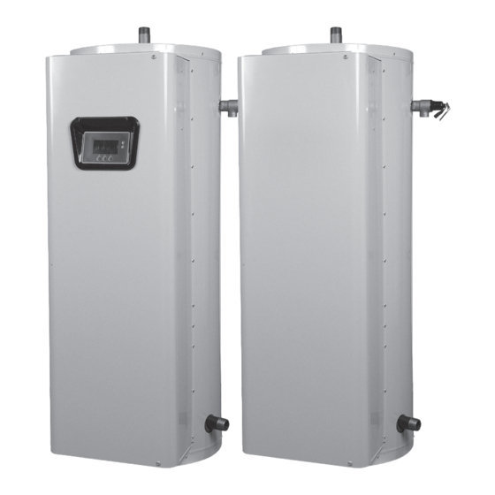
Page 7: Features And Components
features and coMponents electronIc control Models fIGure 1... - Page 8 features and coMponents surface Mount control Models fIGure 2...
-
Page 9: Locating The New Water Heater
locatInG the new water heater facts to consIder aBout the locatIon 2. Near a floor drain. The heater should be located in an area where leakage of the tank or connections will not result in damage to the area adjacent to the heater or to lower floors of the structure. 3. -
Page 10: Installation
InstallatIon reQuIred aBIlIty contaMInated water Installation and service of this water heater requires ability equivalent This water heater shall not be connected to any heating to that of a qualified agency (page 2) in the field involved. Plumbing system(s) or component(s) used with a non-potable water and electrical work is required. -
Page 11: Temperature-Pressure Relief Valve
manufacturer. The valve is certified by a nationally recognized testing laboratory that maintains periodic inspection of production of listed equipment of materials as meeting the requirements for Relief Valves for Hot Water Supply Systems, ANSI Z21.22 • CSA 4.4, and the code requirements of ASME. If replaced, the new valve must meet the requirements of local codes, but not less than a combination temperature and pressure relief valve rated/sized and certified as indicated in the above... -
Page 12: Electrical
electrIcal General The installation must conform with these instructions and the local code authority having jurisdiction and the requirements of the power company. In the absence of local codes, the installation must comply with the current editions of the National Electrical Code, NFPA 70 or the Canadian Electrical Code CSA C22.1. - Page 13 aMperaGe taBle/oVercurrent protectIon limiting, a UIM (User Interface Module) for user interface & information display and element current sensors for monitoring the power circuits. Refer to the control circuit label on the water heater for details. The CCB The tables above provides the total connected heating element load is powered by a small 120V/24V transformer.
- Page 14 wIrInG dIaGraMs ccB (central control Board) cIrcuIt Board control cIrcuIt dIaGraM - electronIc control Models fIGure 3.
- Page 15 wIrInG dIaGraMs power cIrcuIt dIaGraMs - electronIc control Models The water heater’s electrical components are pictured and identified on page 7. The following describes the heater circuits and includes wiring diagrams. All heater circuits are designed for 60/50 hertz alternating current. The water heater circuit wiring is 12 AWG, AWM, or TEW type, rated 600 volts, 105°C.
- Page 16 wIrInG dIaGraMs nIne eleMent - sInGle and three phase dIaGraM 2. conVersIon to sInGle phase conVersIon to three phase When the heater is shipped for connection to a three-phase electrical When heater is shipped for connection to a single-phase electrical service, it may be connected to a single-phase electrical service of service, it may be connected to a three-phase electrical service of the same voltage by:...
- Page 17 wIrInG dIaGraMs power cIrcuIt dIaGraMs - surface Mount control Models The water heater’s electrical components are pictured and identified on page 8. The following describes the heater circuits and includes wiring diagrams. All heater circuits are designed for 60/50 hertz alternating current. The water heater circuit wiring is 12 AWG, AWM, or TEW type, rated 600 volts, 105°C.
- Page 18 wIrInG dIaGraMs nIne eleMents - sInGle and three phase dIaGraM 4. conVersIon to sInGle phase conVersIon to three phase When the heater is shipped for connection to a three-phase electrical When heater is shipped for connection to a single-phase electrical service, it may be connected to a single-phase electrical service of service, it may be connected to a three-phase electrical service of the same voltage by:...
-
Page 19: Operation
operatIon InItIal start up General The following checks should be made by the installer when the Refer to the Features and Components section of this manual heater is placed into operation for the first time. (pages 7 & 8) for the location of components mentioned in the instructions that follow. -
Page 20: Temperature Regulation
teMperature reGulatIon Setting the water heater temperatures at 120°f will reduce the hIGh teMperature lIMIt controls (eco) risk of scalds. Some States require settings at specific lower temperatures. Both the ELECTRONIC CONTROL and SURFACE MOUNT CONTROL model water heaters are equipped with one or more ECO therMostat settInGs - surface Mount control (energy cut off) non adjustable high temperature limit control(s). -
Page 21: Thermostat Settings - Electronic Control Models
The Operating Set Point is adjustable from 90°F/42°C to 190°F/88°C. therMostat settInGs - electronIc controls The factory setting is 120°F/49°C. See the Electronic Control Models Operation section of this manual for instructions on how to adjust the Operating Set Point and other user settings. These models are equipped with an electronic control system. - Page 22 Menu: The left Operational Button is pressed to enter the Main Menu are adjusted in the Economy Mode Setup menu. The current where all control system menus are accessed. See Table 3 for a list Operating Mode, either Normal Mode or Economy Mode, is of control system menus.
-
Page 23: Temperatures Menu
taBle 2 operatInG states. state descrIptIon The water heater is not in an active heating cycle. This usually indicates the temperature in the tank has reached Standby the Operating Set Point and the control system has terminated the heating cycle. Heating The control system is in the Heating Mode. -
Page 24: Temperature Settings
differential settings tank temperature Adjustable user setting(s) 1°F to 20° range; factory default is 2°F. Non adjustable information display. Current water temperature as sensed The water heaters covered in this Instruction Manual will have 3, 6 or by the control system from the immersion Temperature Probe. 9 heating elements. -
Page 25: Heater Status Menu
heater status Menu alarm condition Displays the status of the user definable Alarm Output function - see This menu displays non adjustable operational information. This Alarm Output Setup Menu. Yes = alarm condition has been met, No menu contains more information that can be displayed on one screen = alarm condition has not been met. -
Page 26: Economy Mode Settings
“Normal Operation All Day” - “Economy Mode All Day” and “Normal Normal Operation Between: When this operating mode is active Operation Between.” Only one Operating Mode can be active, the there will also be start and stop times to program. The normal factory default is Normal Operation All Day. - Page 27 econoMy Mode settInGs time clock settings actIon dIsplay From the Desktop Screen navigate to the Economy Mode Setup menu. Use the Up/Down buttons to select (highlight in black) Current Time sub menu. Press the Operational Button underneath “CHANGE” to enter the Current Time sub menu.
-
Page 28: Economy Mode Settings
econoMy Mode settInGs daily operating Mode settings actIon dIsplay Economy Mode All Day: From the Economy Mode Setup menu use the Up/Down buttons to select (highlight in black) the Daily sub menu for “Sun.” Press the Operational Button underneath “CHANGE” to enter this menu. Use the Up/Down buttons to select (highlight in black) the “Economy Mode All Day”... -
Page 29: Alarm Output Setup Menu
alarM output setup Menu dIsplay settInGs Menu Permits user to set display options for viewing information on the Permits user to set the condition (from a list of options) for when UIM’s LCD screen. the CCB’s integral alarm output relay will be energized. Alarm relay connections (common, normally open, normally closed) are located on the J3 terminal strip on the CCB. -
Page 30: Current Fault / Alert Menu
elapsed time This menu displays non adjustable operational information. The control system records and stores the last 9 Fault and Alert Total accumulated time the control system (water heater) has been messages in chronological order in this menu. The most recent energized. -
Page 31: Restore Factory Defaults Menu
restore factory defaults actIon dIsplay From the Main Menu use the Up/Down buttons to select (highlight in black) the “Restore Factory Defaults” menu. Press the Operational Button underneath “SELECT.” The Restore Factory Defaults menu will be displayed. From the Restore Factory Defaults menu press the Operational Button underneath “YES.”... -
Page 32: Flushing
its diameter is 3/8” (1 cm) of an inch, or annually which ever is first. 3. Characteristics of water supply. Aggressive, very hot and softened water causes rapid consumption Regardless of water treatment, the elements should be examined of the anode requiring frequent inspections. Call the toll free number regularly. -
Page 33: Troubleshooting Checklist
trouBleshootInG checklIst checklIst ABNORMAL SOUNDS Before calling for service, check the following points to see if the 1. Sediment or lime scale accumulations on the elements causes cause of trouble can be identified and corrected. sizzling and hissing noises when the heater is operating. •... -
Page 34: Leakage Checkpoints
leakaGe checkpoInts INSTRUCTIONS: USE THIS ILLUSTRATION AS A GUIDE WHEN CHECKING FOR SOURCES OF WATER LEAKAGE. Where possible, remove or lift top cover to examine threads of fittings installed into tank for evidence of leakage. Correct fitting leaks as necessary. Relief valve operation and leakage may be due to water expansion during heating cycle or foreign material on seat of valve. -
Page 35: Piping Diagrams
pIpInG dIaGraMs one teMperature wIth cIrculatInG loop Insert B VacuuM relIef ValVe. Install per local codes. *pIpe to open draIn Install In accordance wIth all local codes. - Page 36 pIpInG dIaGraMs Insert B VacuuM relIef ValVe. Install per local codes.
- Page 37 pIpInG dIaGraMs Insert B VacuuM relIef ValVe. Install per local codes.
- Page 38 pIpInG dIaGraMs one teMperature one heater VertIcal storaGe tank forced cIrculatIon wIthout BuIldInG recIrculatIon *pIpe to open draIn Install In accordance wIth all local codes two teMperature wIth MIXInG ValVe and cIrculatInG loop Insert B VacuuM relIef ValVe. Install per local codes.
- Page 39 pIpInG dIaGraMs Insert B VacuuM relIef ValVe. Install per local codes. two heaters wIth horIZontal storaGe tank wIth or wIthout BuIldInG recIrculatIon...
- Page 40 pIpInG dIaGraMs three heaters wIth VertIcal storaGe tank wIth or wIthout BuIldInG recIrculatIon Insert B VacuuM relIef ValVe. Install per local codes. three heaters wIth horIZontal storaGe tank wIth or wIthout BuIldInG recIrculatIon...
- Page 41 pIpInG dIaGraMs four heaters wIth VertIcal storaGe tank wIth or wIthout BuIldInG recIrculatIon Insert B VacuuM relIef ValVe. Install per local codes. four heaters wIth horIZontal storaGe tank wIth or wIthout BuIldInG recIrculatIon...
-
Page 42: Piping Diagrams
pIpInG dIaGraMs ManIfold kIts ALL DIMENSIONS IN INCHES ManIfold kIts two heaters tank capacity part (gallons) number 9003429205 66 1/4 56 3/4 27 1/4 13 1/4 9003429205 70 1/2 60 1/4 31 1/4 9 3/4 9003429205 73 1/4 64 1/2 35 3/4 5 1/2 Inlet and outlet size - 1 1/2... -
Page 43: Ashland City, Tn
warranty A. O. Smith Corporation, the warrantor, extends the following LIMITED WARRANTY to the owner of this water heater: 1. THE TANK If the glass-lined tank in this water heater shall prove upon examination by the warrantor to have leaked due to natural corrosion from potable water therein, during the first THREE years after initial installation, the warrantor will supply a complete new A. - Page 44 500 Tennessee Waltz Parkway, Ashland City, TN 37015 Technical Support: 800-527-1953 • Parts: 800-433-2545 • Fax: 800-644-9306 www.hotwater.com...
Need help?
Do you have a question about the dre-52 and is the answer not in the manual?
Questions and answers