Intel D915GVWB Product Manual
Desktop board
Hide thumbs
Also See for D915GVWB:
- Specification update (14 pages) ,
- Product brief (4 pages) ,
- Manual (84 pages)
Table of Contents
Advertisement
Advertisement
Table of Contents

Related Manuals for Intel D915GVWB


Summary of Contents for Intel D915GVWB
- Page 1 ® Intel Desktop Board D915GVWB Product Guide C88176-001 Order Number:...
-
Page 2: Revision History
Intel products including liability or warranties relating to fitness for a particular purpose, merchantability, or infringement of any patent, copyright or other intellectual property right. Intel products are not intended for use in medical, life saving, or life sustaining applications. Intel may make changes to specifications and product descriptions at any time, without notice. -
Page 3: Intended Audience
Preface This Product Guide gives information about board layout, component installation, BIOS update, and ® regulatory requirements for Intel Desktop Board D915GVWB. Intended Audience The Product Guide is intended for technically qualified personnel. It is not intended for general audiences. -
Page 4: Box Contents
Intel Desktop Board D915GVWB Product Guide Terminology The table below gives descriptions to some common terms used in the product guide. Term Description Gigabyte (1,073,741,824 bytes) Gigahertz (one billion hertz) Kilobyte (1024 bytes) Megabyte (1,048,576 bytes) Mbit Megabit (1,048,576 bits) -
Page 5: Table Of Contents
Power Management Features....................19 ACPI..........................19 Power Connectors......................19 Fan Connectors......................19 ® Fan Speed Control (Intel Precision Cooling Technology) .......... 19 Suspend to RAM (Instantly Available PC Technology) ..........20 Resume on Ring ......................21 Wake from USB ......................21 Wake from PS/2 Keyboard/Mouse................ - Page 6 Intel Desktop Board D915GVWB Product Guide Use Only for Intended Applications................26 Installing the I/O Shield ......................26 Installing and Removing the Desktop Board ................. 27 Installing and Removing a Processor..................28 Installing a Processor....................28 Installing the Processor Fan Heat Sink ................ 31 Connecting the Processor Fan Heat Sink Cable............
- Page 7 Contents Figures 1. Intel Desktop Board D915GVWB Components .............. 11 2. Location of Standby Power Indicator................20 3. Installing the I/O Shield....................26 4. Mounting Screw Hole Locations ..................27 5. Lift Socket Lever......................28 6. Lift the Load Plate and Don’t Touch the Socket Contacts ..........28 7.
- Page 8 Intel Desktop Board D915GVWB Product Guide viii...
-
Page 9: Desktop Board Features
Main Memory • 400/333 MHz single or dual channel DDR SDRAM interface • Designed to support up to 4 GB of system memory For the latest list of tested memory, refer to the Intel World Wide Web site at: NOTE: http://support.intel.com/support/motherboards/desktop/ ®... -
Page 10: Manufacturing Option
• Voltage sensing to detect out of range values Related Links: For more information about Intel Desktop Board D915GVWB, including the Technical Product Specification (TPS), BIOS updates, and device drivers, go to: http://support.intel.com/support/motherboards/desktop/ Manufacturing Option Table 2 shows the manufacturing option for the Desktop Board D915GVWB. -
Page 11: Desktop Board Components
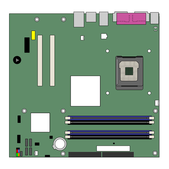
Figure 1 shows the approximate location of the major components on the Desktop Board D915GVWB. Line In RJ45 82915GV (GMCH) Channel A DIMM 0 DIMM 1 Channel B DIMM 0 DIMM 1 OM17366 Figure 1. Intel Desktop Board D915GVWB Components... -
Page 12: Desktop Board D915Gvwb Components
Intel Desktop Board D915GVWB Product Guide Table 3. Desktop Board D915GVWB Components Label Description Front panel audio header (yellow) Rear chassis fan header (fan speed control) 12 V processor core voltage connector (2x2) Processor socket Processor fan header (4-pin, fan speed control) -
Page 13: Processor
CAUTION Failure to use an ATX12V power supply, or not connecting the 12 V (2x2) processor core voltage power supply connector to Desktop Board D915GVWB may result in damage to the desktop board and/or power supply. The Desktop Board D915GVWB supports a single Intel Pentium 4 processor or Intel Celeron D processor in the LGA775 package. -
Page 14: Main Memory
The Intel 915GV Express Chipset consists of the following devices: • Intel 82915GV Graphics and Memory Controller Hub (GMCH) with Digital Media Interface • Intel 82801FB I/O Controller Hub (ICH6) Related Link: Go to the following link for more information about the Intel 915GV Express Chipset: http://developer.intel.com/design/nav/pcserver.htm... -
Page 15: Graphics Subsystem
Intel 915GV Express Chipset • Intel Graphics Media Accelerator 900 Audio Subsystem The Desktop Board D915GVWB includes a flexible 6-channel audio subsystem based on an Intel High Definition Audio codec: The audio subsystem features: • Impedance sensing capability for jack re-tasking •... -
Page 16: Input/Output (I/O) Controller
• Configurable EEPROM that contains the MAC address LAN Subsystem Software For LAN software and drivers, refer to the D915GVWB link on Intel’s World Wide Web site at: http://support.intel.com/support/motherboards/desktop RJ-45 LAN Connector LEDs Two LEDs are built into the RJ-45 LAN connector. Table 4 describes the LED states when the board is powered up and the 10/100 Ethernet LAN subsystem is operating. -
Page 17: Hi-Speed Usb 2.0 Support
Desktop Board Features Hi-Speed USB 2.0 Support NOTE Computer systems that have an unshielded cable attached to a USB port might not meet FCC Class B requirements, even if no device or a low-speed USB device is attached to the cable. Use a shielded cable that meets the requirements for a full-speed USB device. -
Page 18: Bios
Intel Desktop Board D915GVWB Product Guide BIOS The BIOS provides the Power-On Self-Test (POST), the BIOS Setup program, the PCI/PCI Express and IDE auto-configuration utilities, and the video BIOS. The BIOS is stored in the Firmware Hub. The BIOS can be updated by following the instructions on page 53 in Chapter 3. -
Page 19: Power Management Features
It is recommended that processor fan speed control ® remain enabled (default BIOS setting) when using the processor fan heat-sink included with Intel boxed processors. Disabling the chassis fan speed control results in chassis fans always operating at full speed. -
Page 20: Suspend To Ram (Instantly Available Pc Technology)
Intel Desktop Board D915GVWB Product Guide Suspend to RAM (Instantly Available PC Technology) CAUTION For Instantly Available PC technology, the 5 V standby line for the power supply must be capable of delivering adequate +5 V standby current. Failure to provide adequate standby current when using this feature can damage the power supply and/or effect ACPI S3 sleep state functionality. -
Page 21: Resume On Ring
Desktop Board Features Resume on Ring The operation of Resume on Ring can be summarized as follows: • Resumes operation from either ACPI S1 or ACPI S3 state • Requires only one call to access the computer • Detects incoming call similarly for external and internal modems •... - Page 22 Intel Desktop Board D915GVWB Product Guide...
-
Page 23: Installing And Replacing Desktop Board Components
2 Installing and Replacing Desktop Board Components This chapter tells you how to: • Install the I/O shield • Install and remove the desktop board • Install and remove a processor and memory • Connect the IDE and Serial ATA cables •... -
Page 24: Installation Precautions
Intel Desktop Board D915GVWB Product Guide Installation Precautions When you install and test the Intel desktop board, observe all warnings and cautions in the installation instructions. To avoid injury, be careful of: • Sharp pins on connectors • Sharp pins on printed circuit assemblies •... -
Page 25: Chassis And Component Certifications
Installing and Replacing Desktop Board Components Chassis and Component Certifications Ensure that the chassis and certain components; such as the power supply, peripheral drives, wiring, and cables; are components certified for the country or market where used. Agency certification marks on the product are proof of certification. Typical product certifications include: •... -
Page 26: Use Only For Intended Applications
Intel Desktop Board D915GVWB Product Guide Use Only for Intended Applications All Intel desktop boards are evaluated as Information Technology Equipment (I.T.E.) for use in personal computers for installation in homes, offices, schools, computer rooms, and similar locations. The suitability of this product for other applications or environments, such as medical, industrial, alarm systems, test equipment, etc. -
Page 27: Installing And Removing The Desktop Board
Installing and Replacing Desktop Board Components Installing and Removing the Desktop Board WARNING Only qualified technical personnel should do this procedure. Disconnect the computer from its power source before performing the procedures described here. Failure to disconnect the power before you open the computer can result in personal injury or equipment damage. NOTE Refer to Appendix B for regulatory requirements. -
Page 28: Installing And Removing A Processor
Intel Desktop Board D915GVWB Product Guide Installing and Removing a Processor Instructions on how to install the processor to the desktop board are given below. Installing a Processor CAUTION Before installing or removing the processor, make sure AC power has been removed by unplugging the power cord from the computer;... -
Page 29: Remove The Protective Socket Cover
Installing and Replacing Desktop Board Components 4. Remove the plastic protective socket cover from the load plate. Do not discard the protective socket cover. Always replace the socket cover if the processor is removed from the socket (see Figure 7, E). OM17228 Figure 7. -
Page 30: Install Processor
Intel Desktop Board D915GVWB Product Guide 6. Hold the processor with your thumb and index fingers oriented as shown in Figure 9. Make sure fingers align to the socket cutouts (see Figure 9, F). Align notches (see Figure 9, G) with the socket see (Figure 9, H). -
Page 31: Installing The Processor Fan Heat Sink
The desktop board has an integrated processor fan heat sink retention mechanism (RM). For instructions on how to attach the processor fan heat sink to the integrated processor fan heat sink RM, refer to the boxed processor manual or the Intel World Wide Web site at: http://support.intel.com/support/processors/pentium4/intnotes478.htm Connecting the Processor Fan Heat Sink Cable Connect the processor fan heat sink cable to the 4-pin processor fan connector (see Figure 11). -
Page 32: Removing The Processor
Installing and Removing Memory NOTE To be fully compliant with all applicable Intel SDRAM memory specifications, the boards require DIMMs that support the Serial Presence Detect (SPD) data structure. You can access the PC Serial Presence Detect Specification at: http://www.intel.com/technology/memory/pcsdram/spec/... -
Page 33: Dual Configuration Example 2
Installing and Replacing Desktop Board Components If additional memory is to be used, install another matched pair of DIMMs in DIMM 1 (black) in both channels A and B (see Figure 13). Channel A 256 MB, 400 MHz DIMM 0 DIMM 1 512 MB, 400 MHz Channel B... -
Page 34: Installing Dimms
Intel Desktop Board D915GVWB Product Guide Installing DIMMs 1. Observe the precautions in "Before You Begin" on page 23. 2. Turn off all peripheral devices connected to the computer. Turn off the computer and disconnect the AC power cord. 3. Remove the computer’s cover and locate the DIMM sockets (see Figure 15). -
Page 35: Removing Dimms
Installing and Replacing Desktop Board Components 4. Make sure the clips at either end of the DIMM socket(s) are pushed outward to the open position. 5. Holding the DIMM by the edges, remove it from its anti-static package. 6. Position the DIMM above the socket. Align the small notch at the bottom edge of the DIMM with the keys in the socket (see inset in Figure 15). -
Page 36: Connecting The Ide Cable
Observe the precautions in "Before You Begin" on page 23. • Attach the cable end with the single connector to the Intel desktop board (Figure 16, A). • Attach the cable end with the two closely spaced connectors to the drives (Figure 16, B). -
Page 37: Connecting The Serial Ata (Sata) Cable
Installing and Replacing Desktop Board Components Connecting the Serial ATA (SATA) Cable The SATA cable (4-conductor) supports the Serial ATA protocol and connects a single drive to the desktop board. Either end of the cable can be connected to the SATA drive or the connector on the board. -
Page 38: Connecting Internal Headers
Intel Desktop Board D915GVWB Product Guide Connecting Internal Headers Before connecting cables to the internal headers, observe the precautions in "Before You Begin" on page 23. Figure 18 shows the location of the internal headers. Port1L Port1R Presence# Port2R Sense1_Ret... -
Page 39: Connecting The Usb 2.0 Headers
Installing and Replacing Desktop Board Components Connecting the USB 2.0 Headers Before connecting the USB 2.0 headers, observe the precautions in "Before You Begin" on page 23. See Figure 18, D on page 38 for the location of the black USB 2.0 headers. Table 5 shows the pin assignments for the USB 2.0 headers. -
Page 40: Connecting To The Flexible 6-Channel Audio System
Intel Desktop Board D915GVWB Product Guide Connecting to the Flexible 6-Channel Audio System Installing the audio driver from the Intel Express Installer CD-ROM enables the flexible, analog audio system. The back panel audio connectors support up to six speakers and are retaskable using the audio driver interface. -
Page 41: Connecting Fan And Power Cables
Installing and Replacing Desktop Board Components Connecting Fan and Power Cables Connecting Fan Cables Figure 20 shows the location of the fan headers. Connect the processor’s fan heat sink cable to the 4-pin processor fan header on the board. Connect chassis fan cables to the 3-pin fan headers. NOTE If a 3-pin fan connector is used in a 4-pin fan header, the fan will not be controlled and will run at full speed. -
Page 42: Connecting Power Cables
Intel Desktop Board D915GVWB Product Guide Connecting Power Cables CAUTION Failure to use an ATX12V power supply, or not connecting the 12 V (2x2) processor core voltage power supply connector to the desktop board may result in damage to the desktop board and/or power supply. -
Page 43: Connecting 2X12 Power Supply Cables
Installing and Replacing Desktop Board Components Connecting 2x12 Power Supply Cables If you have a 2x12 power supply, follow the instruction below. Figure 22 shows the location of the power connectors. 2X12 OM17361 Figure 22. Connecting 2x12 Power Supply Cables 1. -
Page 44: Other Connectors
Intel Desktop Board D915GVWB Product Guide Other Connectors Figure 23 shows the location of the PCI bus add-in card connectors, PCI Express x1 add-in card connector, and peripheral interface connectors for the desktop board. OM17374 Item Description PCI Express x1 connectors... -
Page 45: Setting The Bios Configuration Jumper Block
Installing and Replacing Desktop Board Components Setting the BIOS Configuration Jumper Block CAUTION Always turn off the power and unplug the power cord from the computer before changing the jumper. Moving the jumper with the power on may result in unreliable computer operation. Figure 24 shows the location of the desktop board’s BIOS configuration jumper. -
Page 46: Clearing Passwords
Intel Desktop Board D915GVWB Product Guide Clearing Passwords This procedure assumes that the board is installed in the computer and the configuration jumper block is set to normal mode. 1. Observe the precautions in "Before You Begin" on page 23. -
Page 47: Back Panel Connectors
Installing and Replacing Desktop Board Components Back Panel Connectors NOTE The line out connector, located on the back panel, is designed to power either headphones or amplified speakers only. Poor audio quality may occur if passive (non-amplified) speakers are connected to this output. Figure 25 shows the location of the back panel connectors. -
Page 48: Replacing The Battery
Intel Desktop Board D915GVWB Product Guide Replacing the Battery A coin-cell battery (CR2032) powers the real-time clock and CMOS memory. When the computer is not plugged into a wall socket, the battery has an estimated life of three years. When the computer is plugged in, the standby current from the power supply extends the life of the battery. - Page 49 Installing and Replacing Desktop Board Components AVVERTIMENTO Esiste il pericolo di un esplosione se la pila non viene sostituita in modo corretto. Utilizzare solo pile uguali o di tipo equivalente a quelle consigliate dal produttore. Per disfarsi delle pile usate, seguire le istruzioni del produttore.
- Page 50 Intel Desktop Board D915GVWB Product Guide AWAS Risiko letupan wujud jika bateri digantikan dengan jenis yang tidak betul. Bateri sepatutnya dikitar semula jika boleh. Pelupusan bateri terpakai mestilah mematuhi peraturan alam sekitar tempatan. OSTRZEŻENIE Istnieje niebezpieczeństwo wybuchu w przypadku zastosowania niewłaściwego typu baterii. Zużyte baterie należy w miarę...
- Page 51 Installing and Replacing Desktop Board Components OСТОРОГА Використовуйте батареї правильного типу, інакше існуватиме ризик вибуху. Якщо можливо, використані батареї слід утилізувати. Утилізація використаних батарей має бути виконана згідно місцевих норм, що регулюють охорону довкілля. ETTEVAATUST ATTENZJONI...
-
Page 52: Removing The Battery
Intel Desktop Board D915GVWB Product Guide To replace the battery, follow these steps: 1. Observe the precautions in "Before You Begin" (see page 23). 2. Turn off all peripheral devices connected to the computer. Disconnect the computer’s power cord from the AC power source (wall outlet or power adapter). -
Page 53: Bios
OM17050 Figure 27. F2 Key This chapter tells you how to update the BIOS by either using the Intel Express BIOS Update utility or the Iflash Memory Update utility, and how to recover the BIOS if an update fails. ®... -
Page 54: Updating The Bios With The Iflash Memory Update Utility
Intel Flash Memory Update Utility You can obtain the BIOS update file through your computer supplier or by navigating to the Desktop Board D915GVWB page on the Intel World Wide Web site at: http://support.intel.com/support/motherboards/desktop ,” and select the Iflash BIOS... -
Page 55: Recovering The Bios
BIOS Recovering the BIOS It is unlikely that anything will interrupt the BIOS update; however, if an interruption occurs, the BIOS could be damaged. The following steps explain how to recover the BIOS if an update fails. The following procedure uses recovery mode for the Setup program. See page 45 for more information on Setup modes. - Page 56 Intel Desktop Board D915GVWB Product Guide...
-
Page 57: A Error Messages And Indicators
A Error Messages and Indicators Desktop Board D915GVWB reports POST errors in two ways: • By sounding a beep code • By displaying an error message on the monitor BIOS Beep Code The BIOS issues a beep code during POST if a memory error occurred. If a repeating beep code is heard and the desktop board does not boot, see Table 9 for beep code descriptions. - Page 58 Intel Desktop Board D915GVWB Product Guide Table 10. BIOS Error Messages (continued) Error Message Explanation A: Drive Error No response from the diskette drive. B: Drive Error CMOS Battery Low The battery may be losing power. Replace the battery soon.
-
Page 59: B Regulatory Compliance
Product Ecology statements • Electromagnetic Compatibility (EMC) regulations • Product certification markings Safety Regulations The Desktop Board D915GVWB complies with the safety regulations stated in Table 11 when correctly installed in a compatible host system. Table 11. Safety Regulations Regulation Title UL 60950-1:2003/ Information Technology Equipment –... - Page 60 Intel Desktop Board D915GVWB Product Guide Tento výrobek odpovídá požadavkům evropských směrnic 89/336/EEC a 73/23/EEC. Čeština Dansk Dette produkt er i overensstemmelse med det europæiske direktiv 89/336/EEC & 73/23/EEC. Dutch Dit product is in navolging van de bepalingen van Europees Directief 89/336/EEC &...
-
Page 61: Product Ecology Statements
In the absence of a viable recycling option, products and their components must be disposed of in accordance with all applicable local environmental regulations. EMC Regulations Desktop Board D915GVWB complies with the EMC regulations stated in Table 12 when correctly installed in a compatible host system. Table 12. - Page 62 Intel Desktop Board D915GVWB Product Guide Japanese Kanji statement translation: this is a Class B product based on the standard of the Voluntary Control Council for Interference from Information Technology Equipment (VCCI). If this is used near a radio or television receiver in a domestic environment, it may cause radio interference.
-
Page 63: Product Certification Markings (Board Level)
Regulatory Compliance Product Certification Markings (Board Level) Desktop Board D915GVWB has the product certification markings shown in Table 13: Table 13. Product Certification Markings Description Mark UL joint US/Canada Recognized Component mark. Includes adjacent UL file number for Intel desktop boards: E210882 (component side). - Page 64 Intel Desktop Board D915GVWB Product Guide...
Need help?
Do you have a question about the D915GVWB and is the answer not in the manual?
Questions and answers