ASROCK Z68 Pro3 Gen3 User Manual
User manual
Hide thumbs
Also See for Z68 Pro3 Gen3:
- Installation manual (15 pages) ,
- Installation manual (4 pages) ,
- Quick installation manual (191 pages)

Related Manuals for ASROCK Z68 Pro3 Gen3


Summary of Contents for ASROCK Z68 Pro3 Gen3
-
Page 1: User Manual
Z68 Pro3 Gen3 User Manual Version 1.0 Published August 2011 Copyright©2011 ASRock INC. All rights reserved. -
Page 2: Copyright Notice
In no event shall ASRock, its directors, of cers, employees, or agents be liable for any indirect, special, incidental, or consequential damages (including damages for... -
Page 3: Table Of Contents
2.5 Installation of Memory Modules (DIMM) ......20 2.6 Expansion Slots ....22 (PCI and PCI Express Slots) 2.7 Dual Monitor and Surround Display Features ....23 2.8 ASRock Smart Remote Installation Guide ..... 26 2.9 Jumpers Setup ............27 2.10 Onboard Headers and Connectors ......28 2.11 Serial ATA (SATA) / Serial ATAII (SATAII) Hard Disks... - Page 4 3 UEFI SETUP UTILITY ..........39 3.1 Introduction ..............39 3.1.1 UEFI Menu Bar ............ 39 3.1.2 Navigation Keys ........... 40 3.2 Main Screen ..............40 3.3 OC Tweaker Screen ............41 3.4 Advanced Screen ............45 3.4.1 CPU Con guration ..........46 3.4.2 North Bridge Con guration........
-
Page 5: Introduction
Chapter 1: Introduction Thank you for purchasing ASRock Z68 Pro3 Gen3 motherboard, a reliable moth- erboard produced under ASRock’s consistently stringent quality control. It delivers excellent performance with robust design conforming to ASRock’s commitment to quality and endurance. In this manual, chapter 1 and 2 contain introduction of the motherboard and step- by-step guide to the hardware installation. -
Page 6: Specifications
Specifications - ATX Form Factor: 12.0-in x 7.5-in, 30.5 cm x 19.1 cm Platform - Premium Gold Capacitor design (100% Japan-made high-quality Conductive Polymer Capacitors) ® - Supports 2nd Generation Intel Core i7 / i5 / i3 in LGA1155 Package - 4 + 2 Power Phase Design ®... - Page 7 - Supports Full HD 1080p Blu-ray (BD) / HD-DVD playback with DVI and HDMI ports - 7.1 CH HD Audio with Content Protection Audio (Realtek ALC892 Audio Codec) - Premium Blu-ray audio support - Supports THX TruStudio - PCIE x1 Gigabit LAN 10/100/1000 Mb/s - Realtek RTL8111E - Supports Wake-On-LAN - Supports LAN Cable Detection...
- Page 8 - Drivers, Utilities, AntiVirus Software (Trial Version), Support CD CyberLink MediaEspresso 6.5 Trial, ASRock Software Suite (CyberLink DVD Suite - OEM and Trial; ASRock MAGIX Multimedia Suite - OEM) - ASRock Extreme Tuning Utility (AXTU) (see CAUTION 9) Unique Feature...
- Page 9 Certifi cations - ErP/EuP Ready (ErP/EuP ready power supply is required) (see CAUTION 20) * For detailed product information, please visit our website: http://www.asrock.com WARNING Please realize that there is a certain risk involved with overclocking, including adjusting the setting in the BIOS, applying Untied Overclocking Technology, or using the third-party overclocking tools.
- Page 10 ASRock Extreme Tuning Utility (AXTU). ASRock website: http://www.asrock.com 10. ASRock Instant Flash is a BIOS ash utility embedded in Flash ROM. This convenient BIOS update tool allows you to update system BIOS without entering operating systems rst like MS-DOS or Windows ®...
- Page 11 - ASRock APP Charger. Simply installing the APP Char- ger driver, it makes your iPhone charged much quickly from your com- puter and up to 40% faster than before. ASRock APP Charger allows you to quickly charge many Apple devices simultaneously and even supports continuous charging when your PC enters into Standby mode (S1), Sus- pend to RAM (S3), hibernation mode (S4) or power off (S5).
- Page 12 17. Although this motherboard offers stepless control, it is not recommended to perform over-clocking. Frequencies other than the recommended CPU bus frequencies may cause the instability of the system or damage the CPU. 18. While CPU overheat is detected, the system will automatically shutdown. Before you resume the system, please check if the CPU fan on the motherboard functions properly and unplug the power cord, then plug it back again.
-
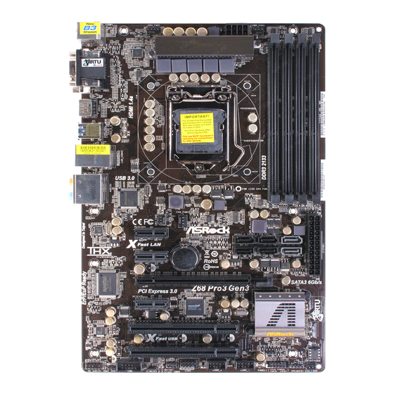
Page 13: Motherboard Layout
USB 3.0 CPU_FAN2 CHA_FAN1 PCIE1 SATA2_5 SATA2_3 SATA3_1 Fast LAN CMOS PCIE2 SATA2_4 SATA2_2 SATA3_0 Battery RoHS PCIE3 Z68 Pro3 Gen3 SATA3 6Gb/s PCI Express 3.0 PCIE4 Intel PCI1 AUDIO CODEC Fast USB PCI2 64Mb PLED1 BIOS USB10_11 COM1 PANEL1... -
Page 14: I/O Panel
1.4 I/O Panel USB 2.0 Ports (USB01) ** 8 Front Speaker (Lime) D-Sub Port Microphone (Pink) LAN RJ-45 Port USB 2.0 Ports (USB45) Central / Bass (Orange) USB 3.0 Ports (USB23) Rear Speaker (Black) HDMI Port Optical SPDIF Out Port DVI-D Port Line In (Light Blue) PS/2 Keyboard Port (Purple) - Page 15 To enable Multi-Streaming function, you need to connect a front panel audio cable to the front panel audio header. After restarting your computer, you will nd “Mixer” tool on your system. Please select “Mixer ToolBox” , click “Enable playback multi-streaming”, and click “ok”.
-
Page 16: Installation
Chapter 2: Installation This is an ATX form factor (12.0" x 7.5", 30.5 x 19.1 cm) motherboard. Before you install the motherboard, study the con guration of your chassis to ensure that the motherboard ts into it. Make sure to unplug the power cord before installing or removing the motherboard. -
Page 17: Cpu Installation
2.3 CPU Installation For the installation of Intel 1155-Pin CPU, please follow the steps below. Load Plate Load Lever Socket Body Contact Array 1155-Pin Socket Overview Before you insert the 1155-Pin CPU into the socket, please check if the CPU surface is unclean or if there is any bent pin on the socket. Do not force to insert the CPU into the socket if above situation is found. - Page 18 Step 3. Insert the 1155-Pin CPU: Step 3-1. Hold the CPU by the edge where is marked with black line. Step 3-2. Orient the CPU with IHS (Integrated Heat Sink) up. Locate Pin1 and the two orientation key notches. orientation key notch alignment key Pin1 Pin1...
-
Page 19: Installation Of Cpu Fan And Heatsink
Installation of CPU Fan and Heatsink This motherboard is equipped with 1155-Pin socket that supports Intel 1155-Pin CPU. Please adopt the type of heatsink and cooling fan compliant with Intel 1155- Pin CPU to dissipate heat. Before you installed the heatsink, you need to spray thermal interface material between the CPU and the heatsink to improve heat dis- sipation. -
Page 20: Installation Of Memory Modules (Dimm)
2.5 Installation of Memory Modules (DIMM) This motherboard provides four 240-pin DDR3 (Double Data Rate 3) DIMM slots, and supports Dual Channel Memory Technology. For dual channel con g- uration, you always need to install identical (the same brand, speed, size and chip-type) DDR3 DIMM pair in the slots: You have to install identical DDR3 DIMM pair in Dual Channel A (DDR3_A1 and DDR3_B1;... -
Page 21: Installing A Dimm
Installing a DIMM Please make sure to disconnect power supply before adding or removing DIMMs or the system components. Step 1. Unlock a DIMM slot by pressing the retaining clips outward. Step 2. Align a DIMM on the slot such that the notch on the DIMM matches the break on the slot. -
Page 22: Expansion Slots (Pci And Pci Express Slots)
2.6 Expansion Slots (PCI and PCI Express Slots) There are 2 PCI slots and 4 PCI Express slots on this motherboard. PCI slots: PCI slots are used to install expansion cards that have the 32-bit PCI interface. PCIE slots: PCIE1 / PCIE2 / PCIE4 (PCIE 2.0 x1 slot) is used for PCI Express cards with x1 lane width cards, such as Gigabit LAN card, SATA2 card, etc. -
Page 23: Dual Monitor And Surround Display Features
2.7 Dual Monitor and Surround Display Features Dual Monitor Feature This motherboard supports dual monitor feature. With the internal VGA output sup- port (DVI-D, D-Sub and HDMI), you can easily enjoy the bene ts of dual monitor feature without installing any add-on VGA card to this motherboard. This mother- board also provides independent display controllers for DVI-D, D-Sub and HDMI to support dual VGA output so that DVI-D, D-sub and HDMI can drive same or different display contents. - Page 24 Surround Display Feature This motherboard supports surround display upgrade. With the internal VGA output support (DVI-D, D-Sub and HDMI) and external add-on PCI Express VGA cards, you can easily enjoy the bene ts of surround display feature. Please refer to the following steps to set up a surround display environment: 1.
- Page 25 ® For Windows 7 / 7 64-bit / Vista / Vista 64-bit OS: Right click the desktop, choose “Personalize”, and select the “Display Settings” tab so that you can adjust the parameters of the multi-monitor according to the steps below. A.
-
Page 26: Asrock Smart Remote Installation Guide
The Multi-Angle CIR Receiver does not support Hot-Plug function. Please install it before you boot the system. * ASRock Smart Remote is only supported by some of ASRock motherboards. Please refer to ASRock website for the motherboard support list: http://www.asrock.com... -
Page 27: Jumpers Setup
2.9 Jumpers Setup The illustration shows how jumpers are setup. When the jumper cap is placed on pins, the jumper is “Short”. If no jumper cap is placed on pins, the jumper is “Open”. The illustration shows a 3-pin jumper whose pin1 and pin2 are “Short”... -
Page 28: Onboard Headers And Connectors
2.10 Onboard Headers and Connectors Onboard headers and connectors are NOT jumpers. Do NOT place jumper caps over these headers and connectors. Placing jumper caps over the headers and connectors will cause permanent damage of the motherboard! Serial ATAII Connectors These four Serial ATAII SATA2_5 SATA2_3... - Page 29 Infrared Module Header This header supports an IRTX +5VSB optional wireless transmitting (5-pin IR1) DUMMY and receiving infrared module. (see p.13 No. 24) IRRX Consumer Infrared Module Header This header can be used to connect the remote (4-pin CIR1) controller receiver. (see p.13 No.
- Page 30 PWRBTN (Power Switch): Connect to the power switch on the chassis front panel. You may con gure the way to turn off your system using the power switch. RESET (Reset Switch): Connect to the reset switch on the chassis front panel. Press the reset switch to restart the computer if the computer freezes and fails to perform a normal restart.
- Page 31 CPU Fan Connectors Please connect the CPU fan FAN_SPEED_CONTROL CPU_FAN_SPEED cable to the connector and (4-pin CPU_FAN1) +12V match the black wire to the (see p.13 No. 1) ground pin. 1 2 3 4 Though this motherboard provides 4-Pin CPU fan (Quiet Fan) support, the 3-Pin CPU fan still can work successfully even without the fan speed control function.
- Page 32 Serial port Header This COM1 header supports a serial port module. (9-pin COM1) (see p.13 No. 26) HDMI_SPDIF Header HDMI_SPDIF header, providing SPDIF audio output to HDMI (2-pin HDMI_SPDIF1) VGA card, allows the system to (see p.13 No. 27) SPDIFOUT connect HDMI Digital TV/ projector/LCD devices.
-
Page 33: Serial Ata (Sata) / Serial Ataii (Sataii) Hard Disks Installation
2.11 Serial ATA (SATA) / Serial ATAII (SATAII) Hard Disks Installation ® This motherboard adopts Intel Z68 chipset that supports Serial ATA (SATA) / Serial ATAII (SATAII) hard disks and RAID (RAID 0, RAID 1, RAID 10, RAID 5, Intel Rapid Storage and Intel Smart Response Technology) functions. -
Page 34: Hot Plug And Hot Swap Functions For Sata / Sataii Hdds
2.13 Hot Plug and Hot Swap Functions for SATA / SATAII HDDs This motherboard supports Hot Plug and Hot Swap functions for SATA / SATAII in ® RAID / AHCI mode. Intel Z68 chipset provides hardware support for Advanced Host controller Interface (AHCI), a new programming interface for SATA host controllers developed thru a joint industry effort. -
Page 35: Sata / Sataii / Sata3 Hdd Hot Plug Feature And Operation Guide
SATA / SATAII / SATA3 Hot Plug support information of our motherboard is indicated in the product spec on our website: www.asrock.com 2. Make sure your SATA / SATAII / SATA3 HDD can support Hot Plug function from your dealer or HDD user manual. - Page 36 How to Hot Plug a SATA / SATAII / SATA3 HDD: Points of attention, before you process the Hot Plug: Please do follow below instruction sequence to process the Hot Plug, improper procedure will cause the SATA / SATAII / SATA3 HDD damage and data loss. Step 1 Step 2 Please connect SATA power cable 1x4-pin end...
-
Page 37: Driver Installation Guide
2.16 Driver Installation Guide To install the drivers to your system, please insert the support CD to your optical drive rst. Then, the drivers compatible to your system can be auto-detected and listed on the support CD driver page. Please follow the order from up to bottom side to install those required drivers. -
Page 38: Installing Windows ® 7 / 7 64-Bit / Vista
2.18 Installing Windows 7 / 7 64-bit / Vista / Vista 64-bit / XP ® / XP 64-bit Without RAID Functions ® If you want to install Windows 7 / 7 64-bit / Vista / Vista 64-bit / XP / XP 64- bit OS on your SATA / SATAII / SATA3 HDDs without RAID functions, please follow below procedures according to the OS you install. -
Page 39: Uefi Setup Utility
Chapter 3: UEFI SETUP UTILITY Introduction This section explains how to use the UEFI SETUP UTILITY to con gure your system. The UEFI chip on the motherboard stores the UEFI SETUP UTILITY. You may run the UEFI SETUP UTILITY when you start up the computer. Please press <F2>... -
Page 40: Navigation Keys
3.1.2 Navigation Keys Please check the following table for the function description of each navigation key. Navigation Key(s) Function Description Moves cursor left or right to select Screens Moves cursor up or down to select items To change option for the selected items + / - To bring up the selected screen <Enter>... -
Page 41: Oc Tweaker Screen
3.3 OC Tweaker Screen In the OC Tweaker screen, you can set up overclocking features. Advanced Turbo 50 You can use this option to increase your system performance. This option appears only when your CPU supports this function. Load Optimized CPU OC Setting You can use this option to load optimized CPU overclocking setting. - Page 42 Please note that enabling this function may reduce CPU voltage and lead to system stability or compatibility issue with some power supplies. Please set this item to [Disable] if above issue occurs. Intel Turbo Boost Technology Use this item to enable or disable Intel Turbo Boost Technology. Turbo Boost allows processor cores to run faster than marked frequency in speci c condition.
- Page 43 CAS# Latency (tCL) Use this item to change CAS# Latency (tCL) Auto/Manual setting. The default is [Auto]. RAS# to CAS# Delay (tRCD) Use this item to change RAS# to CAS# Delay (tRCD) Auto/Manual setting. The default is [Auto]. Row Precharge Time (tRP) Use this item to change Row Precharge Time (tRP) Auto/Manual setting.
- Page 44 ODT NOM (CHA) Use this item to change ODT NOM (CHA) Auto/Manual setting. The de- fault is [Auto]. ODT WR (CHB) Use this item to change ODT WR (CHB) Auto/Manual setting. The default is [Auto]. ODT NOM (CHB) Use this item to change ODT NOM (CHB) Auto/Manual setting. The de- fault is [Auto].
-
Page 45: Advanced Screen
3.4 Advanced Screen In this section, you may set the con gurations for the following items: CPU Con gu- ration, North Bridge Con guration, South Bridge Con guration, Storage Con gura- tion, Super IO Con guration, ACPI Con guration and USB Con guration. Setting wrong values in this section may cause the system to malfunction. -
Page 46: Cpu Configuration
3.4.1 CPU Configuration Intel Hyper Threading Technology To enable this feature, it requires a computer system with an Intel processor that supports Hyper-Threading technology and an operating ® system that includes optimization for this technology, such as Microsoft ® ® ®... - Page 47 CPU Thermal Throttling You may select [Enabled] to enable CPU internal thermal control mechanism to keep the CPU from overheated. Intel Virtualization Technology When this option is set to [Enabled], a VMM (Virtual Machine Architecture) can utilize the additional hardware capabilities provided by Vanderpool Technology.
-
Page 48: North Bridge Configuration
3.4.2 North Bridge Configuration Low MMIO Align Low MMIO resources align at 64MB/1024MB. The default value is [1024M]. VT-d ® ® Use this to enable or disable Intel VT-d technology (Intel Virtualization Technology for Directed I/O). The default value of this feature is [Disabled]. Primary Graphics Adapter This allows you to select [Onboard], [PCI] or [PCI Express] as the boot graphic adapter priority. - Page 49 DVMT Mode Select Use this option to adjust DVMT mode. The default value is [DVMT Mode]. DVMT (Dynamic Video Memory Technology) is an architecture that offers breakthrough performance for the motherboard through ef cient memory utilization. In DVMT mode, the graphics driver allocates memory as needed for running graphics applications and is cooperatively using this memory with other system components.
-
Page 50: South Bridge Configuration
3.4.3 South Bridge Configuration Restore on AC/Power Loss This allows you to set the power state after an unexpected AC/power loss. If [Power Off] is selected, the AC/power remains off when the power recovers. If [Power On] is selected, the AC/power resumes and the system starts to boot up when the power recovers. - Page 51 PCI Legacy Mode This allows you to enable or disable PCI Legacy Mode. The default value is [Enabled]. Good Night LED Enable this option to turn off Power LED and Port80 LED when the system is power on. The keyboard LED will also be turned off in S1, S3 and S4 state.
-
Page 52: Storage Configuration
3.4.4 Storage Configuration SATA Mode Use this to select SATA mode. Con guration options: [IDE Mode], [AHCI Mode], [RAID Mode] and [Disabled]. The default value is [IDE Mode]. AHCI (Advanced Host Controller Interface) supports NCQ and other new features that will improve SATA disk perfor- mance but IDE mode does not have these advantages. -
Page 53: Super Io Configuration
3.4.5 Super IO Configuration Serial Port Use this item to enable or disable the onboard serial port. Serial Port Address Use this item to set the address for the onboard serial port. Con guration options: [3F8 / IRQ4] and [3E8 / IRQ4]. Infrared Port Use this item to enable or disable the onboard infrared port. -
Page 54: Acpi Configuration
3.4.6 ACPI Configuration Suspend to RAM Use this item to select whether to auto-detect or disable the Suspend-to- RAM feature. Select [Auto] will enable this feature if the OS supports it. Check Ready Bit Use this item to enable or disable the feature Check Ready Bit. PS/2 Keyboard Power On Use this item to enable or disable PS/2 keyboard to turn on the system from the power-soft-off mode. -
Page 55: Usb Configuration
3.4.7 USB Configuration USB 2.0 Controller Use this item to enable or disable the use of USB 2.0 controller. USB 3.0 Controller Use this item to enable or disable the use of USB 3.0 controller. Legacy USB Support Use this option to select legacy support for USB devices. There are four con guration options: [Enabled], [Auto], [Disabled] and [UEFI Setup Only]. -
Page 56: Hardware Health Event Monitoring Screen
3.5 Hardware Health Event Monitoring Screen In this section, it allows you to monitor the status of the hardware on your system, including the parameters of the CPU temperature, motherboard temperature, CPU fan speed, chassis fan speed, and the critical voltage. CPU Fan 1 &... -
Page 57: Boot Screen
3.6 Boot Screen In this section, it will display the available devices on your system for you to con g- ure the boot settings and the boot priority. Setup Prompt Timeout This shows the number of seconds to wait for setup activation key. 65535(0XFFFF) means inde nite waiting. -
Page 58: Security Screen
3.7 Security Screen In this section, you may set or change the supervisor/user password for the system. For the user password, you may also clear it. -
Page 59: Exit Screen
3.8 Exit Screen Save Changes and Exit When you select this option, it will pop-out the following message, “Save con guration changes and exit setup?” Select [OK] to save the changes and exit the UEFI SETUP UTILITY. Discard Changes and Exit When you select this option, it will pop-out the following message, “Discard changes and exit setup?”... -
Page 60: Software Support
Click on a speci c item then follow the installation wizard to install it. 4.2.4 Contact Information If you need to contact ASRock or want to know more about ASRock, welcome to visit ASRock’s website at http://www.asrock.com; or you may contact your dealer for further information. - Page 61 Installing OS on a HDD Larger Than 2TB in AHCI Mode ® This motherboard is adopting UEFI BIOS that allows Windows OS to be installed on a large size HDD (>2TB). Please follow below procedure to install the operating system. ®...
-
Page 62: Installing Os On A Hdd Larger Than 2Tb In Raid Mode
You can download the driver from ASRock website. (http://download.asrock.com/drivers/Intel/SATA/Floppy_Win7-64_Win7_Vista64_ Vista_XP64_XP(v10.6.0.1002)Z68.zip) and unzip the fi le into the USB fl ash disk. or Please copy the fi le from ASRock motherboard support CD. (Please copy the fi les under following directory: D:\ AMD64\Win7-64_Vista64_ Intel_v10.6.0.100) 2. - Page 63 d. Plug the USB fl ash disk into your USB port; select “Browse” to fi nd the RAID driver. Then choose the directory (xx\AMD64\) you have copied in the fi rst step. e. Please keep the USB fl ash disk installed until the system fi rst reboot. ®...
- Page 64 b. De-select Local Disks for System Restore. Then Click “Turn System Restore Off” to confi rm. Then Press “Ok”. B. Disable “Volume Shadow Copy” service. a. Type “computer management” in the Start Menu, then press “Enter”.
- Page 65 b. Go to “Services and Applications>Services”; Then double click “Volume Shadow Copy”. c. Set “Startup type” to “Disable” then Click “OK”. C. Reboot your system. D. After reboot, please start to install motherboard drivers and utilities. ® Windows 7 64-bit: A.
- Page 66 5. Finish.
Need help?
Do you have a question about the Z68 Pro3 Gen3 and is the answer not in the manual?
Questions and answers