
Subscribe to Our Youtube Channel
Related Manuals for ASROCK H71M-DGS


Summary of Contents for ASROCK H71M-DGS
-
Page 1: User Manual
H71M-DGS User Manual Version 1.0 Published March 2012 Copyright©2012 ASRock INC. All rights reserved. -
Page 2: Copyright Notice
fi tness for a particular purpose. In no event shall ASRock, its directors, offi cers, employees, or agents be liable for any indirect, special, incidental, or consequential damages (including damages for loss of profi... -
Page 3: Table Of Contents
Contents 1 Introduction ............5 1.1 Package Contents ............5 1.2 Specifi cations ..............6 1.3 Motherboard Layout ............12 1.4 I/O Panel ..............13 2 Installation ............14 2.1 Screw Holes ..............14 2.2 Pre-installation Precautions ......... 14 2.3 CPU Installation ............. 15 2.4 Installation of Heatsink and CPU fan ...... - Page 4 3 UEFI SETUP UTILITY ..........33 3.1 Introduction ..............33 3.1.1 UEFI Menu Bar ............ 33 3.1.2 Navigation Keys ........... 34 3.2 Main Screen ..............34 3.3 OC Tweaker Screen ............35 3.4 Advanced Screen ............40 3.4.1 CPU Confi guration ..........41 3.4.2 North Bridge Confi...
-
Page 5: Introduction
In case any modifi cations of this manual occur, the updated version will be available on ASRock website without further notice. You may fi nd the latest VGA cards and CPU support lists on ASRock website as well. -
Page 6: Specifi Cations
Specifications Platform - Micro ATX Form Factor: 8.9-in x 6.8-in, 22.6 cm x 17.3 cm - Solid Capacitor for CPU power ® - Supports 3 and 2 Generation Intel Core i7 / i5 / i3 in LGA1155 Package ® - Supports Intel Turbo Boost 2.0 Technology - Supports K-Series unlocked CPU - Supports Hyper-Threading Technology (see CAUTION 1) - Page 7 - Dual VGA Output: support DVI-D and D-Sub ports by independent display controllers - Supports DVI with max. resolution up to 1920x1200 @ 60Hz - Supports D-Sub with max. resolution up to 2048x1536 @ 75Hz - Supports HDCP function with DVI port - Supports Full HD 1080p Blu-ray (BD) / HD-DVD playback with DVI port Audio...
- Page 8 Support CD - Drivers, Utilities, AntiVirus Software (Trial Version), CyberLink MediaEspresso 6.5 Trial, Creative Sound Blaster X-Fi MB - Trial, ASRock MAGIX Multimedia Suite - OEM Unique Feature - ASRock Extreme Tuning Utility (AXTU) (see CAUTION 5) - ASRock Instant Boot...
- Page 9 ® Vista / XP. For Windows OS with 64-bit CPU, there is no such limita- tion. You can use ASRock XFast RAM to utilize the memory that Win- ® dows cannot use. The maximum shared memory size is defi ned by the chipset vendor and ®...
- Page 10 - ASRock APP Charger. Simply installing the APP Char- ger driver, it makes your iPhone charged much quickly from your com- puter and up to 40% faster than before. ASRock APP Charger allows you to quickly charge many Apple devices simultaneously and even supports continuous charging when your PC enters into Standby mode (S1), Sus- pend to RAM (S3), hibernation mode (S4) or power off (S5).
- Page 11 ® ® 14. ASRock XFast RAM is not supported by Microsoft Windows XP / XP 64-bit. 15. EuP, stands for Energy Using Product, was a provision regulated by Eu- ropean Union to defi ne the power consumption for the completed system.
-
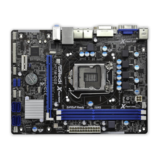
Page 12: Motherboard Layout
CPU_FAN1 ATX12V1 RoHS USB 2.0 T: USB0 B: USB1 USB 2.0 T: USB2 B: USB3 USB 2.0 Top: T: USB4 RJ-45 B: USB5 Fast RAM H71M-DGS PWR_FAN1 PCIE1 Intel AUDIO CODEC CLRCMOS1 CMOS Battery 32Mb BIOS PCIE2 USB8_9 SATA2_3 SATA2_1... -
Page 13: I/O Panel
1.4 I/O Panel PS/2 Mouse Port (Green) USB 2.0 Ports (USB23) LAN RJ-45 Port USB 2.0 Ports (USB01) Line In (Light Blue) DVI-D Port ** 4 Front Speaker (Lime) D-Sub Port Microphone (Pink) PS/2 Keyboard Port (Purple) USB 2.0 Ports (USB45) * There are two LED next to the LAN port. -
Page 14: Installation
Chapter 2: Installation This is a Micro ATX form factor (8.9" x 6.8", 22.6 x 17.3 cm) motherboard. Before you install the motherboard, study the confi guration of your chassis to ensure that the motherboard fi ts into it. Make sure to unplug the power cord before installing or removing the motherboard. -
Page 15: Cpu Installation
2.3 CPU Installation For the installation of Intel 1155-Pin CPU, please follow the steps below. Load Plate Load Lever Socket Body Contact Array 1155-Pin Socket Overview Before you insert the 1155-Pin CPU into the socket, please check if the CPU surface is unclean or if there is any bent pin on the socket. Do not force to insert the CPU into the socket if above situation is found. - Page 16 Step 3. Insert the 1155-Pin CPU: Step 3-1. Hold the CPU by the edge where is marked with black line. Step 3-2. Orient the CPU with IHS (Integrated Heat Sink) up. Locate Pin1 and the two orientation key notches. orientation key notch alignment key Pin1 Pin1...
-
Page 17: Installation Of Cpu Fan And Heatsink
Installation of CPU Fan and Heatsink This motherboard is equipped with 1155-Pin socket that supports Intel 1155-Pin CPU. Please adopt the type of heatsink and cooling fan compliant with Intel 1155- Pin CPU to dissipate heat. Before you installed the heatsink, you need to spray thermal interface material between the CPU and the heatsink to improve heat dis- sipation. -
Page 18: Installation Of Memory Modules (Dimm)
2.5 Installation of Memory Modules (DIMM) This motherboard provides two 240-pin DDR3 (Double Data Rate 3) DIMM slots, and supports Dual Channel Memory Technology. For dual channel configuration, you always need to install two identical (the same brand, speed, size and chip- type) memory modules in the DDR3 DIMM slots to activate Dual Channel Memory Technology. -
Page 19: Expansion Slots (Pci Express Slots)
2.6 Expansion Slots (PCI Express Slots) There are 2 PCI Express slots on this motherboard. PCIE slots: PCIE1 (PCIE 3.0 x16 slot; Blue) is used for PCI Express x16 lane width graphics cards. PCIE2 (PCIE 2.0 x1 slot; White) is used for PCI Express cards with x1 lane width cards, such as Gigabit LAN card, SATA2 card, etc. -
Page 20: Dual Monitor And Surround Display Features
2.7 Dual Monitor and Surround Display Features Dual Monitor Feature This motherboard supports dual monitor feature. With the internal VGA output sup- port (DVI-D and D-Sub), you can easily enjoy the benefi ts of dual monitor feature without installing any add-on VGA card to this motherboard. This motherboard also provides independent display controllers for DVI-D and D-Sub to support dual VGA output so that DVI-D and D-sub can drive same or different display contents. - Page 21 Surround Display Feature This motherboard supports surround display upgrade. With the internal VGA output support (DVI-D and D-Sub) and external add-on PCI Express VGA cards, you can easily enjoy the benefi ts of surround display feature. Please refer to the following steps to set up a surround display environment: 1.
- Page 22 ® For Windows 7 / 7 64-bit / Vista / Vista 64-bit OS: Right click the desktop, choose “Personalize”, and select the “Display Settings” tab so that you can adjust the parameters of the multi-monitor according to the steps below. A.
-
Page 23: Jumpers Setup
2.8 Jumpers Setup The illustration shows how jumpers are setup. When the jumper cap is placed on pins, the jumper is “Short”. If no jumper cap is placed on pins, the jumper is “Open”. The illustration shows a 3-pin jumper whose pin1 and pin2 are “Short”... -
Page 24: Onboard Headers And Connectors
2.9 Onboard Headers and Connectors Onboard headers and connectors are NOT jumpers. Do NOT place jumper caps over these headers and connectors. Placing jumper caps over the headers and connectors will cause permanent damage of the motherboard! Serial ATAII Connectors These four Serial ATAII SATA2_3 SATA2_1... -
Page 25: Front Panel Audio Header
Front Panel Audio Header This is an interface for front PRESENCE# MIC_RET panel audio cable that allows (9-pin HD_AUDIO1) OUT_RET convenient connection and (see p.12 No. 19) control of audio devices. OUT2_L J_SENSE OUT2_R MIC2_R MIC2_L 1. High Defi nition Audio supports Jack Sensing, but the panel wire on the chassis must support HDA to function correctly. - Page 26 HDLED (Hard Drive Activity LED): Connect to the hard drive activity LED on the chassis front panel. The LED is on when the hard drive is reading or writing data. The front panel design may differ by chassis. A front panel module mainly consists of power switch, reset switch, power LED, hard drive activity LED, speaker and etc.
- Page 27 Though this motherboard provides 24-pin ATX power connector, it can still work if you adopt a traditional 20-pin ATX power supply. To use the 20-pin ATX power supply, please plug your power supply along with Pin 1 and Pin 13. 20-Pin ATX Power Supply Installation ATX 12V Power Connector Please connect an ATX 12V...
-
Page 28: Serial Ata (Sata) / Serial Ataii (Sataii) Hard Disks Installation
2.10 Serial ATA (SATA) / Serial ATAII (SATAII) Hard Disks Installation ® This motherboard adopts Intel H61 chipset that supports Serial ATA (SATA) / Serial ATAII (SATAII) hard disks. You may install SATA / SATAII hard disks on this mother- board for internal storage devices. -
Page 29: Sata / Sataii Hdd Hot Plug Feature And Operation Guide
3. Please make sure the SATA / SATAII driver is installed into system properly. The latest SATA / SATAII driver is available on our support website: www.asrock.com 4. Make sure to use the SATA power cable & data cable, which are from our motherboard package. -
Page 30: How To Hot Plug A Sata / Sataii Hdd
How to Hot Plug a SATA / SATAII HDD: Points of attention, before you process the Hot Plug: Please do follow below instruction sequence to process the Hot Plug, improper procedure will cause the SATA / SATAII HDD damage and data loss. Step 1 Step 2 Please connect SATA power cable 1x4-pin end... -
Page 31: Driver Installation Guide
2.13 Driver Installation Guide To install the drivers to your system, please insert the support CD to your optical drive fi rst. Then, the drivers compatible to your system can be auto-detected and listed on the support CD driver page. Please follow the order from up to bottom side to install those required drivers. -
Page 32: 64-Bit / Vista
® STEP 3: Install Windows XP / XP 64-bit OS on your system. ® After making a SATA / SATAII driver diskette, you can start to install Windows ® / XP 64-bit on your system. At the beginning of Windows setup, press F6 to install a third-party AHCI driver. -
Page 33: Uefi Setup Utility
Chapter 3: UEFI SETUP UTILITY Introduction This section explains how to use the UEFI SETUP UTILITY to confi gure your system. The UEFI chip on the motherboard stores the UEFI SETUP UTILITY. You may run the UEFI SETUP UTILITY when you start up the computer. Please press <F2>... -
Page 34: Navigation Keys
3.1.2 Navigation Keys Please check the following table for the function description of each navigation key. Navigation Key(s) Function Description Moves cursor left or right to select Screens Moves cursor up or down to select items + / - To change option for the selected items <Tab>... -
Page 35: Oc Tweaker Screen
3.3 OC Tweaker Screen In the OC Tweaker screen, you can set up overclocking features. CPU Confi guration CPU Turbo Ratio Use this item to change the ratio value of this motherboard. Intel SpeedStep Technology Intel SpeedStep technology is Intel’s new power saving technology. Pro- cessors can switch between multiple frequencies and voltage points to en- able power saving. - Page 36 Short Duration Power Limit Use this item to confi gure short duration power limit in watts. The default value is [Auto]. Primary Plane Current Limit Use this item to confi gure the maximum instantaneous current allowed for the primary plane. The default value is [Auto]. Secondary Plane Current Limit Use this item to confi...
- Page 37 DRAM tRP Use this item to change Row Precharge Time (tRP) Auto/Manual setting. The default is [Auto]. DRAM tRAS Use this item to change RAS# Active Time (tRAS) Auto/Manual setting. The default is [Auto]. Command Rate (CR) Use this item to change Command Rate (CR) Auto/Manual setting. The default is [Auto].
- Page 38 Voltage Confi guration Power Saving Mode Use this to enable or disable Power Saving Mode. The default value is [Disabled]. CPU Core Voltage Offset Use this to select CPU core voltage offset. The default value is [Auto]. IGPU Voltage Offset Use this to select IGPU voltage offset.
-
Page 39: Advanced Screen
3.4 Advanced Screen In this section, you may set the confi gurations for the following items: CPU Confi gu- ration, North Bridge Confi guration, South Bridge Confi guration, Storage Confi gura- tion, Intel(R) Rapid Start Technology, Intel(R) Smart Connect Technology, Super IO Confi... -
Page 40: Cpu Confi Guration
3.4.1 CPU Configuration Intel Hyper Threading Technology To enable this feature, a computer system with an Intel processor that sup- ports Hyper-Threading technology and an operating system that includes ® ® optimization for this technology, such as Microsoft Windows XP / Vista ®... - Page 41 to the IA-32 Intel Architecture. An IA-32 processor with “No Execute (NX) Memory Protection” can prevent data pages from being used by malicious software to execute codes. This option will be hidden if the current CPU does not support No-Excute Memory Protection. Intel Virtualization Technology When this option is set to [Enabled], a VMM (Virtual Machine Architecture) can utilize the additional hardware capabilities provided by Vanderpool...
-
Page 42: North Bridge Confi Guration
3.4.2 North Bridge Configuration Primary Graphics Adapter This allows you to select [Onboard] or [PCI Express] as the boot graphic adapter priority. The default value is [PCI Express]. VT-d ® ® Use this to enable or disable Intel VT-d technology (Intel Virtualization Technology for Directed I/O). -
Page 43: South Bridge Confi Guration
3.4.3 South Bridge Configuration Onboard HD Audio Select [Auto], [Enabled] or [Disabled] for the onboard HD Audio feature. If you select [Auto], the onboard HD Audio will be disabled when PCI Sound Card is plugged. Front Panel Select [Auto] or [Disabled] for the onboard HD Audio Front Panel. Onboard HDMI HD Audio This allows you to enable or disable the “Onboard HDMI HD Audio”... -
Page 44: Storage Confi Guration
3.4.4 Storage Configuration SATA Controller(s) Use this item to enable or disable the SATA Controller feature. SATA Mode Selection Use this to select SATA mode. Confi guration options: [IDE Mode], [AHCI Mode] and [Disabled]. The default value is [AHCI Mode]. AHCI (Advanced Host Controller Interface) supports NCQ and other new features that will improve SATA disk performance but IDE mode does not have these advantages. -
Page 45: Intel(R) Rapid Start Technology
3.4.5 Intel(R) Rapid Start Technology Intel(R) Rapid Start Technology Use this item to enable or disable Intel(R) Rapid Start Technology. Intel(R) Rapid Start Technology is a new zero power hibernation mode which al- lows users to resume in just 5-6 seconds. The default is [Enabled]. Entry After Select a time to enable RTC wake timer at S3 entry. -
Page 46: Intel(R) Smart Connect Technology
3.4.6 Intel(R) Smart Connect Technology Intel(R) Smart Connect Technology Use this item to enable or disable Intel(R) Smart Connect Technology. Intel(R) Smart Connect Technology keeps your e-mail and social networks, such as Twitter, Facebook, etc. updated automatically while the computer is in sleep mode. -
Page 47: Super Io Confi Guration
3.4.7 Super IO Configuration Serial Port Use this item to enable or disable the onboard serial port. Port Address Use this item to set the address for the onboard serial port. Confi guration options: [3F8 / IRQ4] and [3E8 / IRQ4]. Parallel Port Use this item to enable or disable the onboard parallel port. -
Page 48: Acpi Confi Guration
3.4.8 ACPI Configuration Suspend to RAM Use this item to select whether to auto-detect or disable the Suspend-to- RAM feature. Selecting [Auto] will enable this feature if the OS supports it. Check Ready Bit Use this item to enable or disable the feature Check Ready Bit. ACPI HPET Table Use this item to enable or disable ACPI HPET Table. -
Page 49: Usb Confi Guration
3.4.9 USB Configuration USB 2.0 Controller Use this item to enable or disable the use of USB 2.0 controller. Legacy USB Support Use this option to select legacy support for USB devices. There are four confi guration options: [Enabled], [Auto], [Disabled] and [UEFI Setup Only]. The default value is [Enabled]. -
Page 50: Hardware Health Event Monitoring Screen
3.5 Hardware Health Event Monitoring Screen In this section, it allows you to monitor the status of the hardware on your system, including the parameters of the CPU temperature, motherboard temperature, CPU fan speed, chassis fan speed, and the critical voltage. CPU Fan Setting This allows you to set CPU fan’s speed. -
Page 51: Boot Screen
3.6 Boot Screen In this section, it will display the available devices on your system for you to confi g- ure the boot settings and the boot priority. Setup Prompt Timeout This shows the number of seconds to wait for setup activation key. 65535(0XFFFF) means indefi... -
Page 52: Security Screen
3.7 Security Screen In this section, you may set or change the supervisor/user password for the system. For the user password, you may also clear it. -
Page 53: Exit Screen
3.8 Exit Screen Save Changes and Exit When you select this option, the following message “Save confi guration changes and exit setup?” will pop-out. Select [Yes] to save the changes and exit the UEFI SETUP UTILITY. Discard Changes and Exit When you select this option, the following message “Discard changes and exit setup?”... -
Page 54: Software Support
Click on a specifi c item then follow the installation wizard to install it. 4.2.4 Contact Information If you need to contact ASRock or want to know more about ASRock, welcome to visit ASRock’s website at http://www.asrock.com; or you may contact your dealer for further information. - Page 55 Installing OS on a HDD Larger Than 2TB ® This motherboard is adopting UEFI BIOS that allows Windows OS to be installed on a large size HDD (>2TB). Please follow below procedure to install the operating system. ® 1. Please make sure to use Windows Vista 64-bit (with SP1 or above) or ®...
Need help?
Do you have a question about the H71M-DGS and is the answer not in the manual?
Questions and answers