ASROCK A75M User Manual
User manual
Hide thumbs
Also See for A75M:
- Installation manual (27 pages) ,
- Quick installation manual (234 pages) ,
- Manual (234 pages)

Related Manuals for ASROCK A75M


Summary of Contents for ASROCK A75M
-
Page 1: User Manual
A75M User Manual Version 1.1 Published June 2011 Copyright©2011 ASRock INC. All rights reserved. -
Page 2: Copyright Notice
fi tness for a particular purpose. In no event shall ASRock, its directors, offi cers, employees, or agents be liable for any indirect, special, incidental, or consequential damages (including damages for loss of profi... -
Page 3: Table Of Contents
Expansion Slots (PCI and PCI Express Slots) ......18 Dual Graphics Operation Guide ..........19 Dual Monitor and Surround Display Features ......21 ASRock Smart Remote Installation Guide ......... 24 Jumpers Setup ................25 Onboard Headers and Connectors ........26 2.10 Serial ATA3 (SATA3) Hard Disks Installation... - Page 4 3. UEFI SETUP UTILITY............37 Introduction ................37 3.1.1 UEFI Menu Bar ..............37 3.1.2 Navigation Keys ............... 38 Main Screen ................38 OC Tweaker Screen..............39 Advanced Screen ..............42 3.4.1 CPU Confi guration ............43 3.4.2 North Bridge Confi guration ..........44 3.4.3 South Bridge Confi...
-
Page 5: Introduction
In case any modifi cations of this manual occur, the updated ver- sion will be available on ASRock website without further notice. You may fi nd the latest VGA cards and CPU support lists on ASRock website as well. ASRock website http://www.asrock.com... -
Page 6: Specifi Cations
1.2 Specifications Platform - Micro ATX Form Factor: 9.6-in x 8.5-in, 24.4 cm x 21.6 cm - All Solid Capacitor design - Support for Socket FM1 100W processors - Supports AMD’s Cool ‘n’ Quiet Technology - UMI-Link GEN2 Chipset - AMD A75 FCH (Hudson-D3) Memory - Dual Channel DDR3 Memory Technology (see CAUTION 1) - 2 x DDR3 DIMM slots... - Page 7 - PCIE x1 Gigabit LAN 10/100/1000 Mb/s - Realtek RTL8111E - Supports Wake-On-LAN - Supports LAN Cable Detection - Supports Energy Effi cient Ethernet 802.3az - Supports PXE Rear Panel I/O I/O Panel - 1 x PS/2 Mouse Port - 1 x PS/2 Keyboard Port - 1 x D-Sub Port - 1 x HDMI Port - 1 x Optical SPDIF Out Port...
- Page 8 - FCC, CE, WHQL - ErP/EuP Ready (ErP/EuP ready power supply is required) (see CAUTION 14) * For detailed product information, please visit our website: http://www.asrock.com WARNING Please realize that there is a certain risk involved with overclocking, including adjusting the setting in the BIOS, applying Untied Overclocking Technology, or using the third-party over- clocking tools.
- Page 9 6-channel, and 8-channel modes. Please check the table on page 13 for proper connection. ASRock Extreme Tuning Utility (AXTU) is an all-in-one tool to ne-tune different system functions in a user-friendly interface, which is including Hardware Monitor, Fan Control and IES. In Hardware Monitor, it shows the major readings of your system.
- Page 10 ASRock Instant Flash is a BIOS fl ash utility embedded in Flash ROM. This convenient BIOS update tool allows you to update system BIOS ® without entering operating systems fi rst like MS-DOS or Windows . With this utility, you can press <F6> key during the POST or press <F2> key to BIOS setup menu to access ASRock Instant Flash.
- Page 11 For EuP ready power supply selection, we recommend you checking with the power supply manufacturer for more details. Besides, please be noted that if you enable ASRock On/Off Play Technology, your system will not meet EuP standard. To meet EuP standard, please dis-...
-
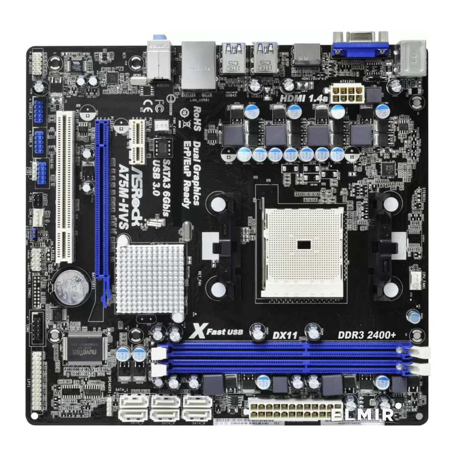
Page 12: Motherboard Layout
21.6cm (8.5-in) Designed in Taipei PWR_FAN1 CPU_FAN1 USB 2.0 T: USB2 B: USB3 USB 3.0 T: USB0 B: USB1 USB 3.0 T: USB4 B: USB5 A75M CMOS BATTERY SATA3 6Gb/s A75 FCH CLRCMOS1 (Hudson-D3) PCIE1 Chipset 32Mb BIOS PCIE2 Fast USB... -
Page 13: I/O Panel
1.4 I/O Panel PS/2 Mouse Port (Green) Microphone (Pink) USB 2.0 Ports (USB23) USB 3.0 Ports (USB45) ** 3 LAN RJ-45 Port USB 3.0 Ports (USB01) Central / Bass (Orange) **** 12 eSATA3 Connector Rear Speaker (Black) HDMI Port Optical SPDIF Out Port D-Sub Port Line In (Light Blue) PS/2 Keyboard Port (Purple) - Page 14 To enable Multi-Streaming function, you need to connect a front panel audio cable to the front panel audio header. After restarting your computer, you will fi nd “Mixer” tool on your system. Please select “Mixer ToolBox” , click “Enable playback multi-streaming”, and click “ok”. Choose “2CH”, “4CH”, “6CH”, or “8CH”...
-
Page 15: Installation
2. Installation This is a Micro ATX form factor (9.6-in x 8.5-in, 24.4 cm x 21.6 cm) motherboard. Before you install the motherboard, study the confi guration of your chassis to ensure that the motherboard fi ts into it. Pre-installation Precautions Take note of the following precautions before you install motherboard components or change any motherboard settings. -
Page 16: Cpu Installation
2.1 CPU Installation Step 1. Unlock the socket by lifting the lever up to a 90 angle. Step 2. Position the CPU directly above the socket such that the CPU corner with the golden triangle matches the socket corner with a small triangle. Step 3. -
Page 17: Installation Of Memory Modules (Dimm)
2.3 Installation of Memory Modules (DIMM) This motherboard provides two 240-pin DDR3 (Double Data Rate 3) DIMM slots, and supports Dual Channel Memory Technology. For dual channel configuration, you always need to install two identical (the same brand, speed, size and chip- type) memory modules in the DDR3 DIMM slots to activate Dual Channel Memory Technology. -
Page 18: Expansion Slots (Pci And Pci Express Slots)
2.4 Expansion Slots (PCI and PCI Express Slots) There are 2 PCI slots and 2 PCI Express slots on this motherboard. PCI Slots: PCI slots are used to install expansion cards that have the 32-bit PCI interface. PCIE Slots: PCIE1 (PCIE x1 slot; White) is used for PCI Express cards with x1 lane width cards, such as Gigabit LAN card and SATA2 card. -
Page 19: Dual Graphics Operation Guide
2.5 AMD Dual Graphics Operation Guide This motherboard supports AMD Dual Graphics feature. AMD Dual Graphics brings multi-GPU performance capabilities by enabling an AMD A75 FCH (Hudson-D3) integrated graphics processor and a discrete graphics processor to operate simultaneously with combined output to a single display for blisteringly-fast frame ®... - Page 20 Step 7. You can also click “AMD VISION Engine Control Center” on your ® Windows taskbar to enter AMD VISION Engine Control Center. AMD VISION Engine Control Center Step 8. In AMD VISION Engine Control Center, please choose “Performance”. Click “AMD CrossFire ”.
-
Page 21: Dual Monitor And Surround Display Features
2.6 Dual Monitor and Surround Display Features Dual Monitor Feature This motherboard supports dual monitor feature. With the internal VGA output sup- port (D-Sub and HDMI), you can easily enjoy the benefi ts of dual monitor feature without installing any add-on VGA card to this motherboard. This motherboard also provides independent display controllers for D-Sub and HDMI to support dual VGA output so that D-sub and HDMI can drive same or different display contents. - Page 22 Surround Display Feature This motherboard supports surround display upgrade. With the internal VGA output support (D-Sub and HDMI) and external add-on PCI Express VGA cards, you can easily enjoy the benefi ts of surround display feature. Please refer to the following steps to set up a surround display environment: 1.
- Page 23 ® For Windows 7 / 7 64-bit / Vista / Vista 64-bit OS: Right click the desktop, choose “Personalize”, and select the “Display Settings” tab so that you can adjust the parameters of the multi-monitor according to the steps below. A.
-
Page 24: Asrock Smart Remote Installation Guide
The Multi-Angle CIR Receiver does not support Hot-Plug function. Please install it before you boot the system. * ASRock Smart Remote is only supported by some of ASRock motherboards. Please refer to ASRock website for the motherboard support list: http://www.asrock.com... -
Page 25: Jumpers Setup
2.8 Jumpers Setup The illustration shows how jumpers are setup. When the jumper cap is placed on pins, the jumper is “Short”. If no jumper cap is placed on pins, the jumper is “Open”. The illustration shows a 3-pin jumper whose pin1 and pin2 are “Short”... -
Page 26: Onboard Headers And Connectors
2.9 Onboard Headers and Connectors Onboard headers and connectors are NOT jumpers. Do NOT place jumper caps over these headers and connectors. Placing jumper caps over the headers and connectors will cause permanent damage of the motherboard! Serial ATA3 Connectors These fi... -
Page 27: Front Panel Audio Header
IRTX Infrared Module Header This header supports an +5VSB DUMMY optional wireless transmitting (5-pin IR1) and receiving infrared module. (see p.12 No. 19) IRRX Consumer Infrared Module Header This header can be used to connect the remote (4-pin CIR1) IRTX IRRX ATX+5VSB controller receiver. - Page 28 RESET (Reset Switch): Connect to the reset switch on the chassis front panel. Press the reset switch to restart the computer if the computer freezes and fails to per- form a normal restart. PLED (System Power LED): Connect to the power status indicator on the chassis front panel. The LED is on when the system is operating.
- Page 29 ATX Power Connector Please connect an ATX power supply to this connector. (24-pin ATXPWR1) (see p.12 No. 7) Though this motherboard provides 24-pin ATX power connector, it can still work if you adopt a traditional 20-pin ATX power supply. To use the 20-pin ATX power supply, please plug your power supply along with Pin 1 and Pin 13.
-
Page 30: Serial Ata3 (Sata3) Hard Disks Installation
2.10 Serial ATA3 (SATA3) Hard Disks Installation This motherboard adopts AMD A75 FCH (Hudson-D3) chipset that supports Serial ATA3 (SATA3) hard disks and RAID (RAID 0, RAID 1 and RAID 10) functions. You may install SATA3 hard disks on this motherboard for internal storage devices. This section will guide you to install the SATA3 hard disks. -
Page 31: Sata3 Hdd Hot Plug Feature And Operation Guide
* The SATA3 Hot Plug feature might not be supported by the chipset because of its limitation, the SATA3 Hot Plug support information of our motherboard is indicated in the product spec on our website: www.asrock.com 2. Make sure your SATA3 HDD can support Hot Plug function from your dealer or HDD user manual. -
Page 32: How To Hot Plug A Sata3 Hdd
How to Hot Plug a SATA3 HDD: Points of attention, before you process the Hot Plug: Please do follow below instruction sequence to process the Hot Plug, improper procedure will cause the SATA3 HDD damage and data loss. Please connect SATA power cable 1x4-pin Step 1 Connect SATA data cable to Step 2... -
Page 33: Driver Installation Guide
STEP 2: Make a SATA3 Driver Diskette. (Please use USB fl oppy or fl oppy disk.) Insert the ASRock Support CD into your optical drive to boot your system. During POST at the beginning of system boot-up, press <F11> key, and then a window for boot devices selection appears. -
Page 34: 64-Bit / Vista
STEP 3: Use “RAID Installation Guide” to set RAID confi guration. Before you start to confi gure RAID function, you need to check the RAID installation guide in the Support CD for proper confi guration. Please refer to the BIOS RAID installation guide part of the document in the following path in the Support CD: .. -
Page 35: Installing Windows
® 2.15 Installing Windows 7 / 7 64-bit / Vista / Vista 64-bit / XP / XP 64-bit Without RAID Functions ® If you want to install Windows 7 / 7 64-bit / Vista / Vista 64-bit / XP / XP 64-bit OS on your SATA3 HDDs without RAID functions, please follow below procedures according to the OS you install. -
Page 36: 64-Bit / Vista
® 2.15.2 Installing Windows 7 / 7 64-bit / Vista / Vista 64-bit Without RAID Functions ® If you want to install Windows 7 / 7 64-bit / Vista / Vista 64-bit on your SATA3 HDDs without RAID functions, please follow below steps. Using SATA3 HDDs with NCQ and Hot Plug functions (AHCI mode) STEP 1: Set up UEFI. -
Page 37: Uefi Setup Utility
3. UEFI SETUP UTILITY 3.1 Introduction This section explains how to use the UEFI SETUP UTILITY to confi gure your sys- tem. The SPI Memory on the motherboard stores the UEFI SETUP UTILITY. You may run the UEFI SETUP UTILITY when you start up the computer. Please press <F2>... -
Page 38: Navigation Keys
3.1.2 Navigation Keys Please check the following table for the function description of each navigation key. Navigation Key(s) Function Description Moves cursor left or right to select Screens Moves cursor up or down to select items + / - To change option for the selected items <Enter>... -
Page 39: Oc Tweaker Screen
3.3 OC Tweaker Screen In the OC Tweaker screen, you can set up overclocking features. CPU Confi guration Spread Spectrum This item should always be [Auto] for better system stability. AMD Turbo Core Technology This item appears only when the processor you adopt supports this fea- ture. - Page 40 DRAM Timing Control Power Down Enable Use this item to enable or disable DDR power down mode. Bank Interleaving Interleaving allows memory accesses to be spread out over banks on the same node, or accross nodes, decreasing access contention. Channel Interleaving It allows you to enable Channel Memory Interleaving.
- Page 41 Refresh Cyle Time (tRFC) Use this item to change Refresh Cyle Time (tRFC) Auto/Manual setting. The default is [Auto]. RAS to RAS Delay (tRRD) Use this item to change RAS to RAS Delay (tRRD) Auto/Manual setting. The default is [Auto]. Write to Read Delay (tWTR) Use this item to change Write to Read Delay (tWTR) Auto/Manual setting.
-
Page 42: Advanced Screen
3.4 Advanced Screen In this section, you may set the confi gurations for the following items: CPU Confi gu- ration, Nouth Bridge Confi guration, South Bridge Confi guration, Storage Confi gura- tion, Super IO Confi guration, ACPI Confi guration, and USB Confi guration. Setting wrong values in this section may cause the system to malfunction. -
Page 43: Cpu Confi Guration
3.4.1 CPU Configuration Core C6 Mode Use this item to enable or disable Core C6 mode. The default value is [Disabled]. Package C6 Mode This item appears only when you enable the item “Core C6 Mode”. Use this item to enable or disable Package C6 mode. The default value is [Dis- abled]. -
Page 44: North Bridge Confi Guration
3.4.2 North Bridge Configuration Primary Graphics Adapter This item will switch the PCI Bus scanning order while searching for video card. It allows you to select the type of Primary VGA in case of multiple video controllers. The default value of this feature is [PCI Express]. Con- fi... -
Page 45: South Bridge Confi Guration
3.4.3 South Bridge Configuration Onboard HD Audio Select [Auto], [Enabled] or [Disabled] for the onboard HD Audio feature. If you select [Auto], the onboard HD Audio will be disabled when PCI Sound Card is plugged. Front Panel Select [Auto] or [Disabled] for the onboard HD Audio Front Panel. On/Off Play Use this item to enable or disable On/Off Play Technology. -
Page 46: Storage Confi Guration
3.4.4 Storage Configuration SATA Controller Use this item to enable or disable the “SATA Controller” feature. SATA Mode Use this item to adjust SATA Mode. The default value of this option is [IDE Mode]. Confi guration options: [AHCI Mode], [RAID Mode] and [IDE Mode]. If you set this item to RAID mode, it is suggested to install SATA ODD driver on SATA_5 and eSATA3 ports. -
Page 47: Super Io Confi Guration
3.4.5 Super IO Configuration Serial Port Use this item to enable or disable the onboard serial port. Serial Port Address Use this item to set the address for the onboard serial port. Confi guration options: [3F8 / IRQ4] and [3E8 / IRQ4]. Infrared Port Use this item to enable or disable the onboard infrared port. -
Page 48: Acpi Confi Guration
3.4.6 ACPI Configuration Suspend to RAM Use this item to select whether to auto-detect or disable the Suspend-to- RAM feature. Select [Auto] will enable this feature if the OS supports it. Check Ready Bit Use this item to enable or disable the feature Check Ready Bit. Restore on AC/Power Loss This allows you to set the power state after an unexpected AC/power loss. - Page 49 ACPI HPET table Use this item to enable or disable ACPI HPET Table. The default value is [Enabled]. Please set this option to [Enabled] if you plan to use this moth- ® erboard to submit Windows Vista certifi cation.
-
Page 50: Usb Confi Guration
3.4.7 USB Configuration USB 2.0 Controller Use this item to enable or disable the use of USB 2.0 controller. USB 3.0 Controller Use this item to enable or disable the use of USB 3.0 controller. Legacy USB Support Use this option to select legacy support for USB devices. There are four confi... -
Page 51: Hardware Health Event Monitoring Screen
3.5 Hardware Health Event Monitoring Screen In this section, it allows you to monitor the status of the hardware on your system, including the parameters of the CPU temperature, motherboard temperature, CPU fan speed, chassis fan speed, and the critical voltage. CPU Fan 1 Setting This allows you to set the CPU fan 1 speed. -
Page 52: Boot Screen
3.6 Boot Screen In this section, it will display the available devices on your system for you to confi g- ure the boot settings and the boot priority. Setup Prompt Timeout This shows the number of seconds to wait for setup activation key. 65535(0xFFFF) means indefi... -
Page 53: Security Screen
3.7 Security Screen In this section, you may set or change the supervisor/user password for the system. For the user password, you may also clear it. -
Page 54: Exit Screen
3.8 Exit Screen Save Changes and Exit When you select this option, it will pop-out the following message, “Save confi guration changes and exit setup?” Select [OK] to save the changes and exit the UEFI SETUP UTILITY. Discard Changes and Exit When you select this option, it will pop-out the following message, “Discard changes and exit setup?”... -
Page 55: Software Support
Click on a specifi c item then follow the installation wizard to install it. 4.2.4 Contact Information If you need to contact ASRock or want to know more about ASRock, welcome to visit ASRock’s website at http://www.asrock.com; or you may contact your... - Page 56 Installing OS on a HDD Larger Than 2TB ® This motherboard is adopting UEFI BIOS that allows Windows OS to be installed on a large size HDD (>2TB). Please follow below procedure to install the operating system. ® 1. Please make sure to use Windows Vista 64-bit (with SP1 or above) or ®...
Need help?
Do you have a question about the A75M and is the answer not in the manual?
Questions and answers