Table of Contents
Advertisement
Owner's Manual
Before using this unit, carefully read the sections entitled: "IMPORTANT
SAFETY INSTRUCTIONS" (p. 2), "USING THE UNIT SAFELY" (pp. 3–4), and
"IMPORTANT NOTES" (pp. 5–6). These sections provide important information
concerning the proper operation of the unit. Additionally, in order to feel
assured that you have gained a good grasp of every feature provided by your
new unit, Owner's Manual should be read in its entirety. The manual should be
saved and kept on hand as a convenient reference.
Copyright © 2003 ROLAND CORPORATION
All rights reserved. No part of this publication may be reproduced in any form without the
written permission of ROLAND CORPORATION.
Advertisement
Table of Contents

Related Manuals for Edirol UA-1000


Summary of Contents for Edirol UA-1000
- Page 1 Owner’s Manual Before using this unit, carefully read the sections entitled: “IMPORTANT SAFETY INSTRUCTIONS” (p. 2), “USING THE UNIT SAFELY” (pp. 3–4), and “IMPORTANT NOTES” (pp. 5–6). These sections provide important information concerning the proper operation of the unit. Additionally, in order to feel assured that you have gained a good grasp of every feature provided by your new unit, Owner’s Manual should be read in its entirety.
-
Page 2: Important Safety Instructions
CAUTION RISK OF ELECTRIC SHOCK DO NOT OPEN ATTENTION : RISQUE DE CHOC ELECTRIQUE NE PAS OUVRIR CAUTION: TO REDUCE THE RISK OF ELECTRIC SHOCK, DO NOT REMOVE COVER (OR BACK). NO USER-SERVICEABLE PARTS INSIDE. REFER SERVICING TO QUALIFIED SERVICE PERSONNEL. INSTRUCTIONS PERTAINING TO A RISK OF FIRE, ELECTRIC SHOCK, OR INJURY TO PERSONS. -
Page 3: Using The Unit Safely
USING THE UNIT SAFELY Used for instructions intended to alert the user to the risk of death or severe injury should improperly. Used for instructions intended to alert the user to the risk of injury or material damage should the unit be used improperly. - Page 4 • Before using the unit in a foreign country, consult with your retailer, the nearest EDIROL/Roland Service Center, or an authorized EDIROL/Roland distributor, as listed on the “Information” page.
-
Page 5: Important Notes
IMPORTANT NOTES 291b In addition to the items listed under “IMPORTANT SAFETY INSTRUCTIONS” and “USING THE UNIT SAFELY” on pages 2 and 4, please read and observe the following: Power Supply • Do not use this unit on the same power circuit with any device that will generate line noise (such as an electric motor or variable lighting system). - Page 6 Handling CD-ROMs • Avoid touching or scratching the shiny underside (encoded surface) of the disc. Damaged or dirty CD-ROM discs may not be read properly. Keep your discs clean using a commercially available CD cleaner. Copyright • Unauthorized recording, distribution, sale, lending, public performance, broadcasting, or the like, in whole or in part, of a work (musical composition, video, broadcast, public performance, or the like) whose copyright is held by a...
-
Page 7: Table Of Contents
Recording a digital input signal ... 33 Synchronizing to the word clock input ... 34 Various settings ...36 Internal blocks of the UA-1000 ... 36 UA-1000 Control Panel ... 36 Adjusting the audio latency... 40 Using ASIO Direct Monitor ... 40 Synchronization settings ...41... -
Page 8: Main Features
In addition, the UA-1000 provides four input/output jacks for effect insertion, MIDI input/output, and word clock input/output jacks for precise recording synchronization with external digital devices. * When the UA-1000 is not connected to a computer, it can function as a multi-channel analog <-> digital converter or an ADAT <-> analog converter. -
Page 9: Power Cord
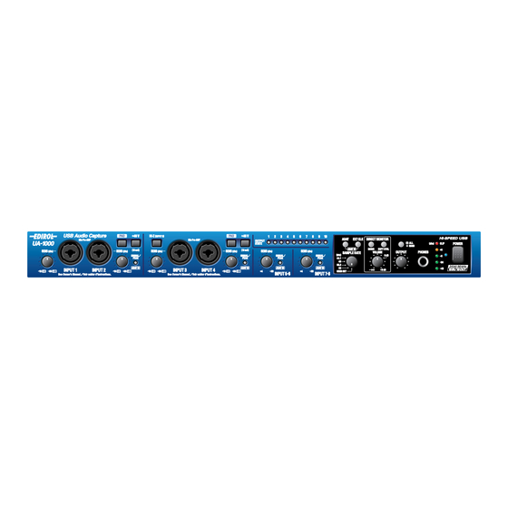
■ UA-1000 fig.ua1000 ■ Power cord This is the only power cord you should use with the UA-1000. Do not use any power cord other than the supplied one, since doing so may cause malfunction. ■ USB cable Use this to connect the USB connector of your computer with the USB connector of the UA-1000. -
Page 10: Attaching The Rackmount Adaptors
Use this when you want to install the UA-1000 in an audio rack. Two rack ears are included. Attaching the rackmount adaptors If you want to install the UA-1000 in a rack, attach the rackmount adaptors as shown in the diagram. fig.angle 1. -
Page 11: Input Sensitivity Knobs
For details on the specifications of your microphone, refer to the owner’s manual for your microphone. (The UA-1000 supplies phantom power at DC 48 V, maximum 10 mA x 2 systems) 4. Gain select switches (PAD) These switch the input level. Turn these on (button in the output gain. -
Page 12: Input Impedance Select Switch
* If you are using ADAT mode, you must set the UA-1000 to 44.1 kHz or 48 kHz. If a setting other than 44.1 kHz or 48 kHz is selected, ADAT mode will not be available; pressing the ADAT mode switch will not cause the ADAT mode switch to light. - Page 13 If you are using external clock mode, this must also match the sampling frequency of your external device. * If you are using the UA-1000 in ADAT mode, set this to 44.1 kHz or 48 kHz. If this is set to anything other than 44.1 kHz or 48 kHz, ADAT mode will not be available;...
-
Page 14: Power Indicator
If you set this to ALL, the knob adjusts the volume of all output jacks together. For details, refer to “Block diagram” (p. 51). Turning off the power of the UA-1000 will not change the setting of this switch. Lower the volume of the connected equipment before you change the setting of the output volume select switch. -
Page 15: Ac Inlet
Connect these to the MIDI connectors of your MIDI device to receive or transmit MIDI messages. 22. WORD CLOCK IN/OUT jacks Use these jacks to synchronize the UA-1000 with a digital recorder. If you want to synchronize to WORD CLOCK, you must turn on the external clock switch. -
Page 16: Insertion / Input Jack Select Switches
Panel Descriptions 27. Insertion / Input jacks 1–4 These can be used either as insertion jacks or as input jacks. Turn the Insertion/Input Select switches on/off to select whether these jacks will function as insertion jacks or as input jacks. For details, refer to “Inserting an external effects processor”... - Page 17 Application of AC230 V Power Cord for UK except for UK...
-
Page 18: Preparations For Using The Ua-1000
Installing the driver What is a driver? A “driver” is software that transfers data between the UA-1000 and application software running on your computer, when your computer and the UA-1000 are connected by a USB cable. The driver sends data from your application to the UA- 1000, and from the UA-1000 to your application. - Page 19 You are now ready to install the driver. Use the USB cable to connect the UA-1000 to your computer. 1. With the power switch turned OFF, connect the power cord to the UA-1000. 2. Connect the power cord to an electrical outlet.
- Page 20 Select “Don’t search. I will choose the driver to install,” and click [Next]. Make sure that the “Model” field indicates “EDIROL UA-1000,” and click [Next]. Driver installation will begin. If the “What action do you want Windows to take?” setting was not set to “Ignore,” a “Hardware Installation”...
- Page 21 This completes installation of the driver. Next, make settings so that Windows will give priority to background services, to ensure that audio and MIDI data are processed smoothly. (-> “Giving priority to background services” (p. 22)) Preparations for using the UA-1000...
-
Page 22: Giving Priority To Background Services
Preparations for using the UA-1000 Giving priority to background services If you fail to make this setting, you may experience interruptions in the sound. To ensure that audio MIDI and processing occurs smoothly, use the following procedure to make settings. -
Page 23: Audio Device
* To prevent audio loops or double monitoring, turn off monitoring in your application or select “Use ASIO Direct Monitor.” * When using the UA-1000 with ASIO, we recommend that you set your application so that it does not use the Microsoft GS Wavetable SW Synth. -
Page 24: Input/Output Device Settings
Preparations for using the UA-1000 Input/output device settings If you are using the UA-1000 with the Media Player included with Windows, use the following procedure to make input/output device settings. The method for making device settings will depend on the software you are using. -
Page 25: About The Demo Songs
Copy the demo songs to the hard disk of your computer, and then load them into your sequencer for playback. • The demo songs were produced at 48 kHz. Set the UA-1000's sampling frequency to 48 kHz. If you change the sampling frequency, you need to switch off the UA-1000, then turn it back on again. -
Page 26: Basic Connections And Settings
Connecting the USB cable allows both MIDI data and audio data to be transferred. As shown in the diagram, you can connect headphones and/or monitor speakers to monitor the playback of your software or the sound of the instruments or audio devices connected to the UA-1000. Computer... -
Page 27: Recording A Mic Or Guitar
Set this to specify whether you will monitor the input signal in stereo or in monaural. ● Direct monitor soft control switch Turn this on if you want to control the INPUT MONITOR from your software. For details, refer to “UA-1000 Control Panel” (p. 36). ● Direct monitor volume Adjust the monitor volume appropriately. -
Page 28: Input Sensitivity Knob
Basic connections and settings ● Input sensitivity knob Use the input sensitivity knob to adjust the input level. To obtain the best audio quality, adjust the input sensitivity knob until the level is as high as you can get it without causing the input peak indicator to light. ●... -
Page 29: Recording Onto An External Adat Device
Recording onto an external ADAT device fig.adat-out ● Connections Connect an optical cable from the OPTICAL OUT jack. ● Sampling frequency select switch Select either 44.1 kHz or 48 kHz. ● ADAT mode switch Press the ADAT mode switch to turn it on. * By pressing the external clock mode switch in ADAT mode, you can use ADAT Output mode to synchronize the word clock or digital input to an external device. -
Page 30: Capturing Sound From An External Adat Device
When audio signals are input from the ADAT to the UA-1000, the PEAK/ SIG/ADAT IN indicators will light green. * If the word clock input connector is connected, the word clock input connector will take priority for synchronization. -
Page 31: Monitoring 5.1 Channel Sound
* For details on UA-1000 Control Panel, refer to “Various settings” (p. 36). In the PATCH BAY area of UA-1000 Control Panel set OUTPUT 1-2 to WAVE OUT 1-2, OUTPUT 3-4 to WAVE OUT 3-4, OUTPUT 5-6 to WAVE OUT 5-6. -
Page 32: Insertion/Input Jack Select Switch
● Insertion/Input jack select switch Since you will be using insertion/input jacks 1--4 as insertion jacks, select INSERT ( ( Signal flow fig.insert-flow External effect processor INPUT Rear INSERT 1 UA-1000 INPUT 1 Front PCS-31 (sold separately) OUTPUT INSERT INPUT White... -
Page 33: Recording A Digital Input Signal
Set this to the same frequency as selected on your digital playback device and your recording software. ● External clock switch So that the UA-1000 will synchronize to the digital signal being input to the digital input jack, turn this on (lit). ● Direct monitor soft control switch Turn this on if you want to control the INPUT MONITOR from your software. -
Page 34: Synchronizing To The Word Clock Input
In order for two or more devices to be synchronized, they must be in the appropriate Word Clock Master and Word Clock Slave relationship. Using the UA-1000 as the master In the setup shown here, the UA-1000 is the master, and the external device (e.g., hard disk recorder) is the slave. fig.synchro-master Hard disk recorder, etc. - Page 35 Using an external device as the master In the setup shown here, the hard disk recorder or other external device is the master, and the UA-1000 is the slave. fig.synchro-slave Hard disk recorder, etc. Set the sampling frequency Match the sampling frequency of the master device ●...
-
Page 36: Various Settings
Various settings You can make various settings for the UA-1000 from your computer. Use UA-1000 Control Panel to make settings. This lets you control the UA-1000’s monitor mixer on/off, volume, on/off, and pan settings. You can also specify the patching. - Page 37 Screen items and what they do Main window fig.control WAVE IN PATCH BAY INPUT MONITOR (DIRECT MONITOR) You can use UA-1000 Control Panel to control each block of the UA-1000. fig.int-block2 INPUT MONITOR (DIRECT MONITOR) 1-10 INPUT 1-10 WAVE IN...
- Page 38 OUTPUT PATCH BAY Here you can select the signals that will be sent to each output jack of the UA-1000. For each output jack, you can choose from the five stereo channels of audio data sent from the computer, the audio data from the UA- 1000's input jacks 1–10, and MONITOR OUT.
-
Page 39: Examples Of Use
Reading and writing memories Five sets of UA-1000 settings can be stored within the UA-1000 itself. These stored memories can be read and written from UA-1000 Control Panel. For the procedure, refer to README_E.HTM on the included CD-ROM. Convenient ways to use the OUTPUT PATCH BAY You can store two different settings for the OUTPUT PATCH BAY, and switch between these two settings. -
Page 40: Adjusting The Audio Latency
For details, refer to the operation manual for your application. Using ASIO Direct Monitor If you are using the UA-1000 in Advanced mode from an ASIO 2.0 compatible application, the UA-1000’s Input Monitor select switch can be controlled from your ASIO 2.0 compatible application. -
Page 41: Synchronization Settings
When you press the ADAT mode switch, the ADAT mode switch will light, and the UA-1000 will be in ADAT Output mode. The signals being output to jacks 1–8 will be converted to ADAT format and sent from the optical digital output jack. The signals will simultaneously be sent from output jacks 1–8 as well. - Page 42 Simultaneously press the ADAT mode switch and the External Clock mode switch. The peak indicator will light in orange, and the UA-1000 will be in ADAT Input mode. The outputs will operate in the same way as in ADAT Output mode.
- Page 43 ■ External clock switch Turn this switch on if you want the UA-1000 to synchronize to the word clock from an external digital device or to the digital signal being input from the digital input jack. If synchronization is occurring correctly, the external clock switch will light, and the UA-1000 will be in external clock mode.
-
Page 44: System Settings
STEREO/MONO select switch Direct monitor soft control switch ADAT EXT CLOCK Output volume mode * For details of the UA-1000's internal block structure when it is shipped from the factory, refer to “Block diagram” (p. 51). State STEREO MAIN Hold down simultaneously... -
Page 45: Troubleshooting
“Find new hardware wizard” ends before the process is completed ● It may take about 15 seconds (or more) after the USB cable is connected for the UA-1000 to be detected. ● Is the USB cable connected correctly? Make sure that the UA-1000 and your computer are correctly connected via a USB cable. -
Page 46: Problems Related To The Ua-1000
● Was the driver installed correctly? In order for you to play back audio data via the UA-1000, the driver must be installed. For installation and settings, refer to “Installing the driver” (p. 18). ● Is your computer in Suspend or Sleep mode? If so, get your computer to resume normal operation, then exit all applications that are using the UA-1000. - Page 47 ● Is a mic or guitar still connected? If a mic or guitar is connected to the UA-1000, disconnect the mic or guitar, and turn the input sensitivity knob all the way to the left. Disconnect any audio devices you are not using.
- Page 48 ● If you are using word clock, noise may be caused by jitter occurring in the master device. If you are using word clock with another digital device as the master and the UA-1000 as the slave, jitter occurring in the master device may cause noise.
- Page 49 Can’t record/play MIDI ● Is the MIDI device you are using set correctly? In order to record/play MIDI tracks via the UA-1000, the UA-1000 driver must be installed correctly. (-> “Installing the driver” (p. 18)) ● Are the track outputs set correctly? You cannot hear MIDI tracks that are not assigned to a MIDI playback device.
-
Page 50: Main Specifications
Main specifications UA-1000: USB 2.0 Audio Capture Number of Audio Record/Playback Channels Record: 10 channels Playback: 10 channels Full duplex Signal Processing PC interface: 24 bits AD/DA Conversion: 24 bits Internal Processing:40 bits Sampling Frequency Digital output: 44.1/48/88.2/96 kHz Digital input: 44.1/48/88.2/96 kHz... -
Page 51: Block Diagram
Block diagram ■Factory settings INPUT MONITOR (DIRECT MONITOR) WAVE OUT SOFT CTRL OFF(BYPASS) MONITOR... - Page 52 Block diagram ■ Output volume select switch: MAIN ■ Output volume select switch: ALL INPUT MONITOR (DIRECT MONITOR) SOFT CTRL WAVE OUT MONITOR ON / OFF(BYPASS) INPUT MONITOR (DIRECT MONITOR) WAVE OUT SOFT CTRL MONITOR ON / OFF(BYPASS)
-
Page 53: Index
MIDI IN device ... 23 MIDI IN/OUT connectors ... 15 MIDI OUT device ... 23 MME ... 23 MME EDIROL UA-1000 ... 23 MONITOR OUT ... 26 optical digital input jack ... 15 optical digital output jack ... 15 Output indicators ... 12 Output jacks ... - Page 54 Rear panel ... 15 Sampling frequency select switch . 13, 27, 29–30, 33–34 STEREO/MONO select switch ... 13, 27 System ... 18 UA-1000 Control Panel ... 36 UA-1000 internal patching ... 31 USB cable ... 9 USB connector ... 15 USER SET ...
-
Page 55: Federal Communications Commission Radio Frequency Interference Statement
Model Name : Type of Equipment : Responsible Party : NOTICE AVIS UA-1000 USB2.0 Audio Interface Edirol Corporation North America Address : 425 Sequoia Drive, Suite 114, Bellingham, WA 98226 Telephone : (360) 594-4276 For EU Countries For the USA... - Page 56 Information When you need repair service, call your nearest EDIROL/Roland Service Center or authorized EDIROL/Roland distributor in your country as shown below. HONG KONG Parsons Music Ltd. 8th Floor, Railway Plaza, 39 EUROPE Chatham Road South, T.S.T, EDIROL (Europe) Ltd.
Need help?
Do you have a question about the UA-1000 and is the answer not in the manual?
Questions and answers