
Related Manuals for B&K CK1.2

Summary of Contents for B&K CK1.2
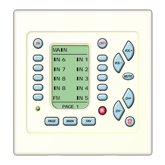
- Page 1 UIDE TO NSTALLATION B & K OF THE CK1.2 K EYPAD MAIN IN 6 IN 1 IN 7 IN 2 IN 8 IN 3 IN 8 IN 4 IN 5 PAGE 1 & Rev B 0104 IMPLY ETTER!
- Page 2 Thank you for choosing to install the B & K CK 1.2 Keypad for this system! Please use this manual as a guide to connecting and mounting the Keypad. The CK1.2 keypad is preprogrammed at the factory to initially operate B &...
-
Page 3: Table Of Contents
Table of Contents Features and Benefits Basic Controls and Displays Rear Panel Connections Programming Jack - Behind the Faceplate Terminate RJ-45’s One to One Standard CT610/310/600 System Configuration Connecting To A CT610/310/600 Keypad Total Power Consumption B & K PT5 Preamp- Perfect for Adding Zones Keypads with Other B&K Preamp/Receivers IR Repeaters for Any Brand of Preamp/Receiver No Emitter for B &... -
Page 4: Features And Benefits
Page 1 Features and Benefits Vast Programming Capacity The CK1.2 can be programmed with 44 IR commands for each of up to 20 components or devices. Additionally, you can label the commands with user friendly names that your client will find easy to use. One Touch Automates Operation The On, Off and all of the screen-labeled buttons can be programmed with macros of up to 190 steps (steps can include IR commands, delays of .1 to... -
Page 5: Basic Controls And Displays
Page 2 Basic Controls and Displays LCD Buttons - Labels on the Screen change depending on what activity has been selected. For example, when CD is the activity, you’ll see the labels change to Play, Stop etc. so that the CD can be controlled. -
Page 6: Rear Panel Connections
Page 3 Rear Panel Connections Master Pin Out MASTER (IN) Connects to the 1 - +12VDC IN 2 - KEYPAD DATA OUT CT610/310/600 via a standard 3 - GROUND 4 Pair Twisted cable (typically 4 - N/C 5 - RS-232 RECEIVE INPUT referred to as CAT 5 cable) 6 - GROUND terminated with an RJ-45 plug. -
Page 7: Programming Jack - Behind The Faceplate
Page 4 Programming Jack - Behind the Faceplate The face plate is removed by prying up from the two screwdriver tabs at the base of the keypad. Once removed, the Programming Jack is revealed: Programming Jack Connect to a laptop PC via the Serial cable included with the CK1.2 keypad. -
Page 8: Standard Ct610/310/600 System Configuration
Page 5 Standard CT610/310/600 System Keypads connect to the Zone Control A/V components con- Connectors on the CT610/310/600 via nect via standard CAT 5 cables. audio and video cables to the num- bered inputs. IR Flashers for A/V com- ponents are connected to the IR output correspon-... -
Page 9: Connecting To A Ct610/310/600
Page 6 Connecting To A CT610/310/600 Keypads connect to the CT610/310/600 at the Control terminals. There is a set of five terminals for each of the hardware Zones labeled A-F on the CT610/600 and A-C on the CT310. You can terminate the Keypad cables to the Control terminals in one of two ways: 1. -
Page 10: Keypad Total Power Consumption
Page 7 Keypad Total Power Consumption The CT610/600 Control 12VDC Outputs can support a Maximum of 26 key- pads total. 13 keypads to each vertical array of three zone control connec- tions. Thus, a CT310 can support a maximum of 13 keypads. If you are supplying power to relays, screens or sensors, these must be counted too. -
Page 11: Keypads With Other B&K Preamp/Receivers
Page 8 Keypads with other B & K Receivers and Preamps The CK1.2 Keypad can be easily programmed with the commands for all remote controlled B & K receivers and preamps. Because of B & K’s elegant all discrete code architecture, the CK1.2 will automate and delight owners of any B &... -
Page 12: No Emitter For B & K Recievers & Preamps
Page 9 No Emitter Needed for B & K Receivers and Preamps B & K receivers and preamps manufactured in the last ten years incorporate a Zone A IR input which will accept IR commands without the addition of a front panel emitter. Utilizing a standard 1/8”... -
Page 13: Connecting Local Tv's And Devices
Page 10 Connecting A Local TV or Device Every keypad can control a local TV or even a local system of components in addition to the components in the main system. A two conductor cable should be run from the Keypad location to the local component location. As many as four infrared emitters can be wired to a keypad by connecting in SERIES as shown here: There is no problem... -
Page 14: Mounting
Page 11 Mounting After connections are made, the CK1.2 installs into a two gang J-Box or an open backed double gang trim ring with the enclosed screws. If you opt to use a closed J-Box, it must be a minimum of 2 3/4” deep to accomodate standard RJ-45 plugs in the rear. -
Page 15: White And Beige Wall Plate Included
Page 12 White and Beige Wall Plate Included Once programming is complete and downloaded to each keypad, finish the installation off by installing either the white or the beige wall plate. The wall plate simply snaps into place, first from the top, finishing with the bottom. Filling Out the Operations Manual for the Client Before training your client, it is best to fill out each room’s Operation Manual. -
Page 16: Specifications
CK1.2 Keypad Specifications AVR507/ 505, REF50, Compatible B & K products PT5, CT610/310/600 Operating Voltage and Current 12VDC @ 75mA Master Inputs 1 RJ-45, 1 Pheonix 5pin Slave Output 1 RJ-45 IR Pass-through Local Flasher Capability Use in line Resistance Installation Requirement Standard Double Gang Keypad Dimensions...
Need help?
Do you have a question about the CK1.2 and is the answer not in the manual?
Questions and answers