Table of Contents
Advertisement
SUPPLEMENTAL SERVICE MANUAL
This is a supplemental Service Manual for Models R-1610, R-1611 and R-1612. These models are quite similar to
base model R-1600,R-1601 and R-1602. Use this supplemental manual together with the Base Models Service
Manual (Reference No. is S4910R1160X//) for complete operation, service information, etc..
BEFORE SERVICING ...................................................................................................... INSIDE FRONT COVER
WARNING TO SERVICE PERSONNEL ................................................................................................................ 1
MICROWAVE MEASUREMENT PROCEDURE ................................................................................................... 2
FOREWORD AND WARNING ............................................................................................................................... 3
PRODUCT SPECIFICATIONS .............................................................................................................................. 4
GENERAL INFORMATION ................................................................................................................................... 4
OPERATION .......................................................................................................................................................... 6
TROUBLESHOOTING GUIDE .............................................................................................................................. 8
TEST PROCEDURE .............................................................................................................................................. 9
TOUCH CONTROL PANEL ASSEMBLY ............................................................................................................ 11
CONPONENT REPLACEMENT AND ADJUSTMENT PROCEDURE ................................................................ 14
PICTORIAL DIAGRAM ........................................................................................................................................ 16
POWER UNIT CIRCUIT ...................................................................................................................................... 17
LSI UNIT CIRCUIT ............................................................................................................................................... 18
INDICATOR CIRCUIT .......................................................................................................................................... 19
PARTS LIST ........................................................................................................................................................ 20
PACKING AND ACCESSORIES ......................................................................................................................... 25
SHARP CORPORATION
MODELS
HELP
TURNTAB LE
OFF
COOK
SENSOR DEFROST
S e n s o r C o o k i n g
Custom
Baked
Sensor
Help
Popcor n
potato
reheat
Frozen
Frozen
vegetab les
Frozen
Fresh
snacks
vegetab les
entrees
Fish/
Ground
Rice
Poultry
seafood
meat
More from your Microw ave
One Dish
Lunch on
Breakfast
Dinners
the Run
Bar
Compu
Beverage
Super
Defrost
Center
Defrost
1
2
3
4
5
6
7
8
9
0
Turntable
Memory
Power
Minute
On/Off
Cook
Level
Plus
Kitchen Timer
Stop
START
Clock
Clear
Touch On
Work
Night
Fan
Auto
Light
Light
Hi/Lo
Fan
In the interest of user-safety the oven should be restored to its original
condition and only parts identical to those specified should be used.
WARNING TO SERVICE PERSONNEL: Microwave ovens con-
tain circuitry capable of producing very high voltage and
current. Contact with the following parts may result in a
severe, possibly fatal, electrical shock. (High Voltage Capaci-
tor, High Voltage Power Transformer, Magnetron, High Volt-
age Rectifier Assembly, High Voltage Harness etc..)
TABLE OF CONTENTS
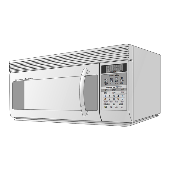
OVER THE RANGE
MICROWAVE OVEN
R-1610
R-1611
R-1612
This document has been published to be used for after
sales service only.
The contents are subject to change without notice.
R-1610
R-1611
R-1612
S5911R1610X//
Page
Advertisement
Table of Contents

Related Manuals for Sharp R-1612


Summary of Contents for Sharp R-1612
-
Page 1: Table Of Contents
Rectifier Assembly, High Voltage Harness etc..) This is a supplemental Service Manual for Models R-1610, R-1611 and R-1612. These models are quite similar to base model R-1600,R-1601 and R-1602. Use this supplemental manual together with the Base Models Service Manual (Reference No. -
Page 2: Precautions To Be Observed Before And During Servicing To Avoid Possible Exposure To Excessive Microwave Energy
Before servicing an operative unit, perform a microwave emission check as per the Microwave Measurement Procedure outlined in this service manual. If microwave emissions level is in excess of the specified limit, contact SHARP ELECTRONICS CORPORATION immediately @1-800-237-4277. If the unit operates with the door open, service person should 1) tell the user not to operate the oven and 2) contact SHARP ELECTRONICS CORPORATION and Food and Drug Administration's Center for Devices and Radiological Health immediately. -
Page 3: Warning To Service Personnel
R-1610 R-1611 R-1612 WARNING TO SERVICE PERSONNEL Microwave ovens contain circuitry capable of pro- ducing very high voltage and current, contact with following parts may result in a severe, possibly fatal, electrical shock. (Example) High Voltage Capacitor, High Voltage Power Trans- former, Magnetron, High Voltage Rectifier Assem- bly, High Voltage Harness etc.. -
Page 4: Microwave Measurement Procedure
R-1610 R-1611 R-1612 MICROWAVE MEASUREMENT PROCEDURE A. Requirements: 1) Microwave leakage limit (Power density limit): The power density of microwave radiation emitted by a microwave oven should not exceed 1mW/cm at any point 5cm or more from the external surface of the oven, measured prior to acquisition... - Page 5 This Manual has been prepared to provide Sharp Electronics Corp. Service Personnel with Operation and Service Information for the SHARP OVER THE RANGE MICROWAVE OVEN, R-1610/ R-1611/ R1612. The models R-1610, R-1611 and R-1612 are quite similar to base models R-1600, R-1601 and R-1602 (Reference No. is S3910R1600X//).
-
Page 6: Product Specifications
R-1610 R-1611 R-1612 PRODUCT SPECIFICATION ITEM DESCRIPTION Power Requirements 120 Volts / 14 Amperes 60 Hertz Single phase, 3 wire grounded Power Output 1000 watts (IEC-705 TEST PROCEDURE) Operating frequency of 2450MHz Case Dimensions Width 29-15/16" Height 16-3/8" Depth 15- 1/16" (Not including the door handle) Cooking Cavity Dimensions Width 21"... -
Page 7: General Information
R-1610 R-1611 R-1612 GENERAL INFORMATION GROUNDING INSTRUCTIONS This oven is equipped with a three prong grounding plug. It must be plugged into a wall receptacle that is properly installed and grounded in accordance with the National Electrical Code and local codes and ordinances. -
Page 8: Operation
R-1610 R-1611 R-1612 OPERATION DESCRIPTION OF OPERATING SEQUENCE any vapor from the oven cavity and sensor. SENSOR COOKING CONDITION NOTE: During this first stage, do not open the door or touch Using the Sensor Cooking function, the foods are cooked or STOP/CLEAR pad. - Page 9 R-1610 R-1611 R-1612 SCHEMATIC NOTE: CONDITION OF OVEN 1. DOOR CLOSED CAVITY MAGNETRON CLOCK APPEARS ON DISPLAY THERMAL CUT-OUT TEMPERATURE FUSE CONTROL UNIT COM. N.O. AH SENSOR FUSE POWER TRANSFORMER HOOD FAN THERMAL High CUT OUT N.C. DOOR SENSING SWITCH HOOD 120 V AC.
-
Page 10: Troubleshooting Guide
R-1610 R-1611 R-1612 TROUBLESHOOTING GUIDE Never touch any part in the circuit with your hand or an uninsulated tool while the power supply is connected. When troubleshooting the microwave oven, it is helpful to follow the Sequence of Operation in performing the checks. Many of the possible causes of trouble will require that a specific test be performed. - Page 11 R-1610 R-1611 R-1612 TEST PROCEDURES PROCEDURE COMPONENT TEST LETTER KEY UNIT TEST 1. Disconnect the power supply cord, and then remove outer case. 2. Open the door and block it open. 3. Discharge high voltage capacitor. 4. If the display fails to clear when the STOP/CLEAR pad is depressed, first verify the flat ribbon cable is making good contact, verify that the door sensing switch (stop switch) operates properly;...
- Page 12 R-1610 R-1611 R-1612 TEST PROCEDURES PROCEDURE COMPONENT TEST LETTER NOTE: ERROR will appear if the door is opened or STOP/CLEAR pad is touched during first stage of sensor cooking. (6) After approximately 32 seconds, microwave energy is produced, and the display should start to count down the remaining cooking time and oven should turn off after water is boiling (bubbling).
-
Page 13: Touch Control Panel Assembly
R-1610 R-1611 R-1612 TEST PROCEDURES PROCEDURE COMPONENT TEST LETTER (18) Carry out “Water load cooking test” again and ensure that the oven works properly. Plunger R1, R2 : 22 1% 1/2W R3 : 4.3k 5% 1/4W R4 : 1M 5% 1/4W To connector (F) on Control Unit. -
Page 14: Description Of Lsi
R-1610 R-1611 R-1612 DESCRIPTION OF LSI LSI(IZA958DR) The I/O signal of the LSI(IZA958DR) is detailed in the following table. Pin No. Signal Description NOTE: For additional informations of LSI, please refer back to the R-1600/1601/ 1602 base model Service Manual. - Page 15 R-1610 R-1611 R-1612 ABSOLUTE HUMIDITY SENSOR CIRCUIT (1) Structure of Absolute Humidity Sensor balance the bridge circuit is deviated to increase the The absolute humidity sensor includes two thermistors voltage available at AN1 terminal of the LSI. as shown in the illustration. One thermistor is housed in...
-
Page 16: Conponent Replacement And Adjustment Procedure
3. The door gasket or seal is damaged. 4. If the outer case (cabinet) is not fitted. WARNING FOR WIRING To prevent an electric shock, take the following pre- 3) Sharp edge: cautions. Bottom plate, Oven cavity, Waveguide flange, 1. Before wiring, Chassis support and other metallic plate. - Page 17 R-1610 R-1611 R-1612 14.Remove the hood duct from the oven cavity by lifting it up. 18.Now, the oven lamp socket is free. 15.Screw the oven lamp off from the lamp socket. 19.Release the harness of the AH sensor assembly from 16.Remove the lamp socket from the lamp angle.
- Page 18 R-1610 R-1611 R-1612...
-
Page 19: Power Unit Circuit
R-1610 R-1611 R-1612 2SB1238 R4 27 D1-4 R5 4.7k 11ES1 – – 510 1/2w 2SB1238 R2 680 1/2w C100 MOTOR RUN 7 /230v CAPACITOR TURNTABLE TURNTABLE MOTOR MOTOR PKM22EPT BUZZER R6 3.3k R20 1k 1/2w HOOD LAMP HOOD LAMP C110 0.033 /250v... - Page 20 R-1610 R-1611 R-1612 SEG6 SEG7 SEG8 SEG9 SEG10 SEG11 SEG12 SEG13 SEG14 SEG15 SEG16 SEG17 SEG18 SEG19 TEST SEG20 OSC1 OSC2 AVSS AN11 SEG35 AN10 /50v 4.7k C110 /25v 0.01 330p/50v 330p/50v 330p/50v 4.7K (J17) (J16) 330p/50v 330p/50v 4.7K (J15)
- Page 21 R-1610 R-1611 R-1612 SENSOR DEFROST TURNTABLE OFF COOK HELP SEG9 SEG35 SEG8 SEG36 SEG7 SEG37 SEG6 SEG38 SEG5 SEG39 SEG4 COM16 /50v SEG3 COM15 C129 SEG2 COM14 SEG1 COM13 SEG0 COM12 COM7 COM11 COM6 COM10 COM5 COM9 COM4 COM8 COM3...
-
Page 22: Parts List
2- 7 FANGKB009MRY0 Hood lamp glass assembly [R-1610] 2- 7 FANGKB010MRY0 Hood lamp glass assembly [R-1611] 2- 7 FANGKB011MRY0 Hood lamp glass assembly [R-1612] 2-7-1 LANGQB016MRP0 Hood lamp glass angle [R-1610] 2-7-1 LANGQB020MRP0 Hood lamp glass angle [R-1611] 2-7-1 LANGQB027MRP0... - Page 23 Zener diode (HZ-161) 3- 2 FPNLCB263MRK0 Control panel sub. assembly [R-1610] 3- 2 FPNLCB264MRK0 Control panel sub, assembly [R-1611] 3- 2 FPNLCB265MRK0 Control panel sub, assembly [R-1612] 3- 2-1 FUNTKB213MRE0 Key unit [R-1610] 3- 2-1 FUNTKB214MRE0 Key unit [R-1611] 3- 2-1 FUNTKB215MRE0...
- Page 24 To have your order filled promptly and correctly, please furnish the following information. 1. MODEL NUMBER 2. REF. NO. 3. PART NO. 4. DESCRIPTION Order Parts from the authorized SHARP parts Distributor for your area. Defective parts requiring return should be returned as indicated in the Service Policy.
- Page 25 R-1610 R-1611 R-1612 OVEN AND CABINET PARTS 7-10 6-17 1-14 4-13 1-18 4-19 4-10 4-12 4-11 1-12 1-15 1-16 1-13 1-17 4-17 6-10 4-18 4-24 4-20 4-23 4-25 6-16 6-12 4-22 4-20 1-10 1-11 4-14 1-10 4-16 7-11 6-13 7-10...
- Page 26 R-1610 R-1611 R-1612 CONTROL PANEL PARTS 3-2-2 3-2-3 3-2-1 4-21 DOOR PARTS 5-2-5 5-2-1 5-2-3 MISCELLANEOUS 5-2-2 5-2-4 6-1-1 6-1-4 6-15 6-1-5 6-1-2 6-1-6 6-11 6-1-7 6-1-3...
-
Page 27: Packing And Accessories
RACK HOLDER SPADFB047MRE0 DOOR PAD SPADFA020WRE0 INSTALL MATERIAL ASSEMBLY 6-3 OPERATION MANUAL WALL TEMPLATE BOTTOM PAD SPADBB025MRE0 INSTALLATION INSTRUCTION 6-4 TOP TEMPLATE 6-13 GREASE FILTER (x 2) ACCESSORY HOLDER SPADFB045MRE0 PACKING CASE Non-replaceable items SPAKCB233MRR12 [R-1610] SPAKCB233MRR13 [R-1611] SPAKCB233MRR14 [R-1612]... - Page 28 No part of this publication may be repro- duced, stored in retrieval systems, or trans- mitted in any form or by any means, elec- tronic, mechanical, photocopying, record- ing, or otherwise, without prior written per- mission of the publisher. '99 SHARP CORP. (5S2.530E) Printed in U.S.A...
Need help?
Do you have a question about the R-1612 and is the answer not in the manual?
Questions and answers