Table of Contents
Advertisement
Advertisement
Table of Contents

Subscribe to Our Youtube Channel
Related Manuals for Asus P8Z77-I DELUXE/WD


Summary of Contents for Asus P8Z77-I DELUXE/WD
- Page 1 P8Z77-I DELUXE/WD...
- Page 2 Product warranty or service will not be extended if: (1) the product is repaired, modified or altered, unless such repair, modification of alteration is authorized in writing by ASUS; or (2) the serial number of the product is defaced or missing.
-
Page 3: Table Of Contents
Product highlights................ 1-1 1.1.2 Dual Intelligent Processors 2 with DIGI+ VRM ......1-2 1.1.3 ASUS Exlusive Features ............. 1-3 1.1.4 ASUS Quiet Thermal Solution ............. 1-5 1.1.5 ASUS EZ DIY ................1-5 1.1.6 Other special features ..............1-6 Motherboard overview ................1-8 1.2.1... - Page 4 Network Stack ................3-30 Monitor menu ................... 3-31 Boot menu ....................3-34 Tools menu ....................3-36 3.8.1 ASUS EZ Flash 2 Utility ............3-36 3.8.2 ASUS SPD Information ............. 3-36 3.8.3 ASUS O.C. Profile ..............3-36 Exit menu ....................3-37 3.10...
- Page 5 USB 3.0 Boost................4-16 4.3.10 USB Charger+ ................4-17 4.3.11 USB BIOS Flashback Wizard............ 4-19 4.3.12 Network iControl................ 4-21 4.3.13 ASUS Wi-Fi Engine ..............4-24 4.3.14 ASUS Update ................4-27 4.3.15 MyLogo2 ................... 4-28 4.3.16 Audio configurations..............4-29 RAID support RAID configurations ..................
- Page 6 LucidLogix Virtu MVP LucidLogix Virtu MVP ................7-1 7.1.1 Installing LucidLogix Virtu MVP ........... 7-1 7.1.2 Setting up your display ..............7-2 7.1.3 Configuring LucidLogix Virtu MVP ..........7-3 Appendices Notices ........................A-1 ASUS contact information ..................A-5...
-
Page 7: Safety Information
Safety information Electrical safety • To prevent electrical shock hazard, disconnect the power cable from the electrical outlet before relocating the system. • When adding or removing devices to or from the system, ensure that the power cables for the devices are unplugged before the signal cables are connected. If possible, disconnect all power cables from the existing system before you add a device. -
Page 8: About This Guide
Refer to the following sources for additional information and for product and software updates. ASUS websites The ASUS website provides updated information on ASUS hardware and software products. Refer to the ASUS contact information. Optional documentation Your product package may include optional documentation, such as warranty flyers, that may have been added by your dealer. -
Page 9: Conventions Used In This Guide
Conventions used in this guide To ensure that you perform certain tasks properly, take note of the following symbols used throughout this manual. DANGER/WARNING: Information to prevent injury to yourself when completing a task. CAUTION: Information to prevent damage to the components when completing a task IMPORTANT: Instructions that you MUST follow to complete a task. -
Page 10: P8Z77-I Deluxe/Wd Specifications Summary
Supports Intel Turbo Boost Technology 2.0* ® * The Intel Turbo Boost Technology 2.0 support depends on the CPU types. ® ** Refer to www.asus.com for Intel CPU support list Chipset Intel Z77 Express Chipset ® Memory 2 x DIMM, max. 16GB, DDR3 2400 (O.C.)* / 2200 (O.C.)* / 2133 (O.C.) / 1866 (O.C.) / 1600 / 1333 / 1066 MHz, non-ECC, un-buffered memory... - Page 11 BIOS features 64 Mb Flash ROM, UEFI AMI BIOS, PnP, DMI 2.0, WfM 2.0, SM BIOS 2.5, ACPI 2.0a, Multi-language BIOS, ASUS EZ Flash 2, ASUS CrashFree BIOS 3, F12 PrintScreen function, F3 Shortcut function, and ASUS DRAM SPD (Serial Presence Detect) memory...
- Page 12 P8Z77-I DELUXE/WD specifications summary ASUS Dual Intelligent Processors 2 with DIGI+ VRM ASUS unique features - Industry leading digital 10-phase power design (8-phase for CPU, 2-phase for iGPU) ASUS EPU - EPU ASUS TPU - Auto Tuning, TurboV, GPU Boost, TPU switch...
- Page 13 1 x S/PDIF out header 1 x Clear CMOS jumper 1 x chassis instrusion header 1 x speaker header Support DVD contents Drivers ASUS Utilities ASUS Update Anti-virus software (OEM version) Accessories 2 x Wi-Fi ring moving antennas 2 x Serial ATA 6.0Gb/s cables 2 x Serial ATA 3.0Gb/s cables...
-
Page 14: Package Contents
User manual Support DVD motherboard 2 x Serial ATA 6.0 Gb/s cables 1 bag of screws 1 x ASUS Q-Shield 2 x Serial ATA 3.0 Gb/s cables 2 x Wi-Fi Ring moving antennas 1 x ASUS Q-Cable • If any of the above items is damaged or missing, contact your retailer. -
Page 15: Installation Tools And Components
Installation tools and components 1 bag of screws Philips (cross) screwdriver PC chassis Power supply unit Intel LGA 1155 CPU Intel LGA 1155 compatible CPU Fan DIMM SATA hard disk drive SATA optical disc drive (optional) Graphics card (optional) The tools and components in the table above are not included in the motherboard package. -
Page 17: Product Introduction
Product introduction Special features 1.1.1 Product highlights LGA1155 socket for Intel 2nd/3rd Generation Core™ i7 / Core™ i5 / Core™ i3 ® / Pentium and Celeron Processors ® ® This motherboard supports the Intel® 3rd/2nd generation Core™ i7/i5/i3/Pentium®/Celeron® processors in the LGA1155 package, with iGPU, memory, and PCI Express controllers integrated to support onboard graphics out with dedicated chipsets, 2-channel (2 DIMMs) DDR3 memory, and 16 PCI Express 3.0/2.0 lanes. -
Page 18: Dual Intelligent Processors 2 With Digi+ Vrm
Complete USB 3.0 Integration ASUS facilitates the strategic USB 3.0 accessibility for both the front and rear panel – 6 USB 3.0 ports in total. Experience the latest plug & play connectivity at speeds up to 10 times faster than USB 2.0. The P8Z77-I DELUXE/WD affords greater convenience to high speed connectivity. -
Page 19: Asus Exlusive Features
Ai Charger+ ASUS Ai Charger+, the latest Ai Charger* version, brings you to a new level of USB3.0 fast charging experience. With its easy and user-friendly interface, you can not only easily charge iPods, iPhones and iPads, but also BC 1.1** standard mobile devices three times*** as fast... -
Page 20: Gpu Boost
AI Suite II With its user-friendly interface, ASUS AI Suite II consolidates all the exclusive ASUS features into one simple to use software package. It allows you to supervise overclocking, energy management, fan speed control, voltage and sensor readings, and even interact with mobile devices via Wi-Fi. -
Page 21: Asus Quiet Thermal Solution
Electronic Magnetic Interference (EMI). ASUS EZ-Flash 2 ASUS EZ Flash 2 is a user-friendly utility that allows you to update the BIOS without using a bootable floppy disk or an OS-based utility. P8Z77-I DELUXE/WD... -
Page 22: Other Special Features
1.1.6 Other special features Intel Wireless Display (WiDi) Intel Wireless Display enables wireless streaming of content from your desktop to the ® big screen. Favorite movies, family videos, or precious photos - everything looks great in complete clarity, so sharing is easier and more fun. Plus, it works well for productivity and business presentations, upscaling your experience in multiple ways. -
Page 23: Dts Connect
The motherboard is European Union’s Energy-related Products (ErP) ready. ErP requires products to meet certain energy efficiency requirement with regard to energy consumption. This is in line with the ASUS vision of creating environment-friendly and energy-efficient products through product design and innovation. -
Page 24: Motherboard Overview
Motherboard overview 1.2.1 Before you proceed Take note of the following precautions before you install motherboard components or change any motherboard settings. • Unplug the power cord from the wall socket before touching any component. • Before handling components, use a grounded wrist strap or touch a safely grounded object or a metal object, such as the power supply case, to avoid damaging them due to static electricity. -
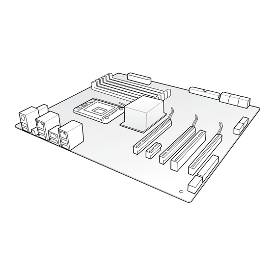
Page 25: Motherboard Layout
1.2.2 Motherboard layout 17cm(6.7in) DIGI +VRM CON21 CON3 CON123 USB1-4 CON22 CHA_FAN SPDIFO _HDMI 1442 CPU_FAN 1042 MemOK! LAN_USB3_E12 Intel WG82579V SATA6G_1 SATA6G_2 SATA3G_1 USB56 SATA3G_2 ESATA3G12 _USB3 BIOS Intel ® FLBK_LED USB78 CLR_CMOS_BFLASH CLRTC SPDIF_OUT AUDIO SPEAKER USB3_34 F_PANEL 898-GR SB_PWR PCIEX16... -
Page 26: Layout Contents
Layout contents Connectors/Jumpers/Slots Page 1. CPU and chassis fan connectors (4-pin CPU_FAN,4-pin CHA_FAN) 1-30 2. LGA1155 CPU socket 1-11 3. DDR3 DIMM slots 1-12 4. ATX power connectors (24-pin EATXPWR, 8-pin EATX12V) 1-32 5. TPU switch 1-25 6. Speaker connector (4- pin SPEAKER) 1-32 7. -
Page 27: Central Processing Unit (Cpu)
Contact your retailer immediately if the PnP cap is missing, or if you see any damage to the PnP cap/socket contacts/motherboard components. ASUS will shoulder the cost of repair only if the damage is shipment/ transit-related. -
Page 28: System Memory
1.2.4 System memory The motherboard comes with four Double Data Rate 3 (DDR3) Dual Inline Memory Modules (DIMM) slots. A DDR3 module is notched differently from a DDR or DDR2 module. DO NOT install a DDR or DDR2 memory module to the DDR3 slot. P8Z77-I DELUXE/WD 240-pin DDR3 DIMM sockets Recommended memory configurations Chapter 1: Product introduction... -
Page 29: Memory Configurations
• The maximum 64GB memory capacity can be supported with 16GB or above DIMMs. ASUS will update the memory QVL once the DIMMs are available in the market. • The default memory operation frequency is dependent on its Serial Presence Detect (SPD), which is the standard way of accessing information from a memory module. - Page 30 P8Z77-I DELUXE/WD Motherboard Qualified Vendors Lists (QVL) DDR3 2400(O.C.) MHz capability DIMM socket support Chip Chip (Optional) Vendors Part No. Size Timing Voltage Brand 1 DIMM 2 DIMMs CORSAIR CMGTX8(XMP) 8GB(2GB x 4) SS 10-12-10-27 1.65V • • G.SKILL F3-19200CL11Q-16GBZHD(XMP) 16GB(4GB x4) DS 11-11-11-31 1.65V •...
- Page 31 DDR3 2133(O.C.) MHz capability DIMM socket support Chip Chip (Optional) Vendors Part No. Size Timing Voltage Brand 1 DIMM 2 DIMMs A-DATA AX3U2133GC2G9B-DG2(XMP) 9-11-9-27 1.55~1.75V • • CORSAIR CMT16GX3M4X2133C9(XMP 1.3) 16GB(4GB x4) DS 9-11-10-27 1.50V • • CORSAIR CMT4GX3M2A2133C9(XMP) 4GB(2x 2GB) 9-10-9-24 1.65V •...
- Page 32 DDR3 1600 MHz capability DIMM socket Chip support (Optional) Vendors Part No. Size Chip NO. Timing Voltage Brand 1 DIMM 2 DIMM 3CCD-1509A A-DATA AM2U16BC2P1 A-DATA • • EL1126T A-DATA AD31600E001GM(O)U3K 3GB(3 x 1GB) 8-8-8-24 1.65V-1.85V • • A-DATA AX3U1600XB2G79-2X(XMP) 4GB(2 x 2GB) 7-9-7-21 1.55V-1.75V •...
- Page 33 DDR3 1600 MHz capability DIMM socket Chip support (Optional) Vendors Part No. Size Chip NO. Timing Voltage Brand 1 DIMM 2 DIMMs Super Talent WA160UX6G9 6GB(3 x 2GB) DS • • Transcend JM1600KLN-8GK 8GB(4GBx2) Transcend TK483PCW3 • • Asint SLZ3128M8-EGJ1D(XMP) Asint 3128M8-GJ1D 9-9-9-24 1.6V •...
- Page 34 DDR3 1333 MHz capability DIMM socket support (Optional) Vendors Part No. Size Chip Brand Chip NO. Timing Voltage 1 DIMM 2 DIMMs GEIL GV32GB1333C9DC 2GB(2x1GB) DS 9-9-9-24 1.5V • • 1.3V(low GEIL GG34GB1333C9DC 4GB(2x2GB) DS GEIL GL1L128M88BA12N 9-9-9-24 • • voltage) GEIL GV34GB1333C9DC...
- Page 35 DDR3 1333 MHz capability DIMM socket support (Optional) Vendors Part No. Size Chip Brand Chip NO. Timing Voltage 1 DIMM 2 DIMMs Transcend TS256MLK64V3U Micron 9GF27D9KPT • • Century PC3-10600 DDR3-1333 9-9-9 NANYA NT5CB128M8DN-CF • • Elixir M2F2G64CB88B7N-CG Elixir N2CB2G80BN-CG •...
- Page 36 Hyper DIMM support is subject to the physical characteristics of individual CPUs. Load the X.M.P. or D.O.C.P. settings in the BIOS for the hyper DIMM support. • Visit the ASUS website for the latest QVL. Chapter 1: Product introduction 1-20...
-
Page 37: Expansion Slots
1.2.5 Expansion slots Unplug the power cord before adding or removing expansion cards. Failure to do so may cause you physical injury and damage motherboard components. Slot No. Slot Description PCIe 3.0/2.0 x16 slot (x16) • The PCIe 3.0 speed is supported by Intel 3rd generation Core™... -
Page 38: Irq Assignments For This Motherboard
IRQ assignments for this motherboard Intel PCH SATA – – – shared – – – – Controller #0 Intel PCH SATA – – – shared – – – – Controller #1 SMBUS Controller – shared – – – – – Thermal Controller –... -
Page 39: Onboard Switches
BIOS default settings. A message will appear during POST reminding you that the BIOS has been restored to its default settings. • We recommend that you download and update to the latest BIOS version from the ASUS website at www.asus.com after using the MemOK! function. P8Z77-I DELUXE/WD 1-23... -
Page 40: Onboard Leds
TPU switch Enable this switch to automatically optimize the system for fast, yet stable clock speeds. Enable this switch when the system is powered off. TPU Boost P8Z77-I DELUXE/WD TPU Boost switch • The TPU LED (O2LED2) near the TPU switch lights up when the TPU switch is enabled. - Page 41 TPU LED The TPU LED lights up when the TPU switch is changed to Enable. TPU_LED P8Z77-I DELUXE/WD TPU Boost LED BIOS_FLBK LED The BIOS_FLBK LED lights up when the BIOS-FLBK function is enabled. FLBK_LED P8Z77-I DELUXE/WD FLBK LED DRAM LED DRAM LED checks the DRAM in sequence during the motherboard booting process.
-
Page 42: Internal Connectors
1.2.8 Internal connectors Intel Z77 Serial ATA 6.0 Gb/s connectors (7-pin SATA6G_1/2 [gray]) ® These connectors connect to Serial ATA 6.0 Gb/s hard disk drives via Serial ATA 6.0 Gb/s signal cables. If you installed Serial ATA hard disk drives, you can create a RAID 0, 1, 5, and 10 configuration with the Intel Rapid Storage Technology through the onboard Intel ®... - Page 43 Intel Z77 Serial ATA 3.0 Gb/s connectors (7-pin SATA3G_3-6 [blue]) ® These connectors connect to Serial ATA 3.0 Gb/s hard disk drives and optical disc drives via Serial ATA 3.0 Gb/s signal cables. If you installed Serial ATA hard disk drives, you can create a RAID 0, 1, 5, and 10 configuration with the Intel Rapid Storage Technology through the onboard Intel ®...
- Page 44 USB 3.0 connector (20-1 pin USB3_34) This connector is for additional USB 3.0 ports, and complies with the USB 3.0 specificaton that supports up to 5Gbps connection speed. A USB 3.0 front panel cable available with your system chassis can be used with this connector to set up front panel USB 3.0 ports.
- Page 45 Never connect a 1394 cable to the USB connectors. Doing so will damage the motherboard! The USB 2.0 module is purchased separately. Digital audio connector (4-1 pin SPDIF_OUT) This connector is for an additional Sony/Philips Digital Interface (S/PDIF) port. Connect the S/PDIF Out module cable to this connector, then install the module to a slot opening at the back of the system chassis.
- Page 46 These are not jumpers! Do not place jumper caps on the fan connectors! • The CPU_FAN connector supports the CPU fan of maximum 1A (12W) fan power. • Only the CPU_FAN, CHA_FAN connectors support the ASUS FAN Xpert feature. Chapter 1: Product introduction 1-30...
- Page 47 Front panel audio connector (10-1 pin AAFP) This connector is for a chassis-mounted front panel audio I/O module that supports either HD Audio or legacy AC`97 audio standard. Connect one end of the front panel audio I/O module cable to this connector. AAFP PIN 1 PIN 1...
- Page 48 • If you are uncertain about the minimum power supply requirement for your system, refer to the Recommended Power Supply Wattage Calculator at http://support.asus. com/PowerSupplyCalculator/PSCalculator.aspx?SLanguage=en-us for details. Speaker connector (4- pin SPEAKER) This 4-pin connector is for the chassis-mounted system warning speaker.
- Page 49 System panel connector (10-1 pin PANEL) This connector supports several chassis-mounted functions. The ASUS Q-Cable allows you to easily connect or disconnect the chassis front panel cables even when you have already installed the components and installed the motherboard to the chassis.
- Page 50 1.2.9 Jumper Clear RTC RAM (3-pin CLRTC) This jumper allows you to clear the Real Time Clock (RTC) RAM in CMOS. You can clear the CMOS memory of date, time, and system setup parameters by erasing the CMOS RTC RAM data.
-
Page 51: Basic Installation
Basic Installation Building your PC system 2.1.1 CPU installation The LGA1156 CPU is not compatible with the LGA1155 socket. DO NOT install a LGA1156 CPU on the LGA1155 socket. P8Z77-I DELUXE/WD... -
Page 52: Cpu Heatsink And Fan Assembly Installation
2.1.2 CPU heatsink and fan assembly installation Apply the Thermal Interface Material to the CPU heatsink and CPU before you install the heatsink and fan if necessary. Chapter 2: Getting started... - Page 53 To install the CPU heatsink and fan assembly P8Z77-I DELUXE/WD...
- Page 54 To uninstall the CPU heatsink and fan assembly Chapter 2: Getting started...
-
Page 55: Dimm Installation
2.1.3 DIMM installation To remove a DIMM P8Z77-I DELUXE/WD... -
Page 56: Motherboard Installation
2.1.5 Motherboard installation The diagrams in this section are for reference only. The motherboard layout may vary with models, but the installation steps are the same for all models. To install the P8Z77-I DELUXE/WD into a chassis: Locate and remove the two screws near the Vcore card on the motherboard using a screw driver. - Page 57 Place the motherboard into the chassis with the rear I/O ports aligned to the chassis’s rear I/O panel. Place four screws into the holes indicated by circles in the illustration below to secure the motherboard to the chassis. Use the screws you removed earlier for holes indicated with A, and two screws bundled with the chassis for holes indicated with B.
-
Page 58: Atx Power Connection
2.1.6 ATX Power connection Chapter 2: Getting started... -
Page 59: Sata Device Connection
2.1.7 SATA device connection P8Z77-I DELUXE/WD... -
Page 60: Front I/O Connector
2.1.8 Front I/O Connector To install front panel Connector (or Q-cable) To install USB 2.0 connector To install front panel audio connector AAFP USB 2.0 To install USB 3.0 connector USB 3.0 Chapter 2: Getting started 2-10... -
Page 61: Expansion Card Installation
2.1.9 Expansion Card installation To install PCIe x16 cards P8Z77-I DELUXE/WD 2-11... -
Page 62: Bios Update Utility
• Updating the BIOS may have risks. If the BIOS program is damaged during the process and results in the system’s failure to boot up, please contact your local ASUS Service Center. Chapter 2: Getting started... -
Page 63: Motherboard Rear And Audio Connections
2. Optical S/PDIF Out port 9. External SATA ports 1 and 2 3. Modified antenna ports (Wi-Fi 802.11 10. Asmedia USB 3.0 ports 1 and 2, and Bluetooth v4.0/3.0+HS)* support ASUS USB 3.0 UASP Mode 4. Intel LAN (RJ-45) port** 11. DVI-I port ®... - Page 64 • Press the Clear CMOS switch to clear BIOS setup information only when the system hangs due to overclocking. • DO NOT insert a different connector to the external SATA port. • Due to USB 3.0 controller limitations, USB 3.0 devices can only be used under a Windows OS environment and after USB 3.0 driver installation.
- Page 65 2.3.2 Audio I/O connections Audio I/O ports Connect to Headphone and Mic Connect to Stereo Speakers P8Z77-I DELUXE/WD 2-15...
- Page 66 Connect to 2.1 channel Speakers Connect to 4.1 channel Speakers Connect to 5.1 channel Speakers Chapter 2: Getting started 2-16...
-
Page 67: Starting Up For The First Time
Connect to 7.1 channel Speakers When the DTS UltraPC II function is enabled, connect the rear speaker to the gray port. Starting up for the first time After making all the connections, replace the system case cover. Ensure that all switches are off. Connect the power cord to the power connector at the back of the system chassis. -
Page 68: Turning Off The Computer
BIOS Beep Description One short beep VGA detected Quick boot set to disabled No keyboard detected One continuous beep followed by two short No memory detected beeps then a pause (repeated) One continuous beep followed by three short No VGA detected beeps One continuous beep followed by four short Hardware component failure... -
Page 69: Bios Setup
BIOS setup Knowing BIOS The new ASUS UEFI BIOS is a Unified Extensible Interface that complies with UEFI architecture, offering a user-friendly interface that goes beyond the traditional keyboard- only BIOS controls to enable a more flexible and convenient mouse input. You can easily navigate the new UEFI BIOS with the same smoothness as your operating system. -
Page 70: Bios Setup Program
BIOS setup program Use the BIOS Setup to update the BIOS or configure its parameters. The BIOS screen include navigation keys and brief onscreen help to guide you in using the BIOS Setup program. Entering BIOS at startup To enter BIOS Setup at startup: •... -
Page 71: Ez Mode
3.2.1 EZ Mode By default, the EZ Mode screen appears when you enter the BIOS setup program. The EZ Mode provides you an overview of the basic system information, and allows you to select the display language, system performance mode and boot device priority. To access the Advanced Mode, click Exit/Advanced Mode, then select Advanced Mode or press <F7>... -
Page 72: Advanced Mode
3.2.2 Advanced Mode The Advanced Mode provides advanced options for experienced end-users to configure the BIOS settings. The figure below shows an example of the Advanced Mode. Refer to the following sections for the detailed configurations. To access the Advanced Mode, click Exit, then select Advanced Mode or press F7 hotkey. Back button Menu items Menu bar... -
Page 73: Menu Items
Menu items The highlighted item on the menu bar displays the specific items for that menu. For example, selecting Main shows the Main menu items. The other items (Ai Tweaker, Advanced, Monitor, Boot, Tool, and Exit) on the menu bar have their respective menu items. -
Page 74: Main Menu
Main menu The Main menu screen appears when you enter the Advanced Mode of the BIOS Setup program. The Main menu provides you an overview of the basic system information, and allows you to set the system date, time, language, and security settings. Security The Security menu items allow you to change the system security settings. -
Page 75: Administrator Password
• If you have forgotten your BIOS password, erase the CMOS Real Time Clock (RTC) RAM to clear the BIOS password. See section 1.2.6 Onboard buttons and switches for information on how to erase the RTC RAM via the Clear CMOS button. •... -
Page 76: Ai Tweaker Menu
To change a user password: Select the User Password item and press <Enter>. From the Enter Current Password box, key in the current password, then press <Enter>. From the Create New Password box, key in a new password, then press <Enter>. Confirm the password when prompted. - Page 77 This item appears only when you set the Ai Overclocking Tuner item to [X.M.P.] and allows you to select the X.M.P. mode supported by your memory module. Configuration options: [Profile #1] [ Profile #2] ASUS MultiCore Enhancement [Enabled] [Enabled] Default set to [Enabled] for maximum performance under XMP/Manual/ User-defined memory frequency mode.
- Page 78 Internal PLL Overvoltage [Auto] Allows you to set the internal PLL voltage. Configuration options: [Auto] [Enabled] [Disabled] CPU bus speed : DRAM speed ratio mode [Auto] Allows you to set the CPU bus speed to DRAM speed ratio mode. [Auto] DRAM speed is set to the optimized settings.
-
Page 79: Dram Timing Control
DRAM Timing Control The subitems in this menu allow you to set the DRAM timing control features. Use the <+> and <-> keys to adjust the value. To restore the default setting, type [auto] using the keyboard and press the <Enter> key. Changing the values in this menu may cause the system to become unstable! If this happens, revert to the default settings. - Page 80 Secondary Timings DRAM RAS# to RAS# Delay [Auto] Configuration options: [Auto] [1 DRAM Clock] – [15 DRAM Clock] DRAM REF Cycle Time [Auto] Configuration options: [Auto] [1 DRAM Clock] – [511 DRAM Clock] DRAM Refresh Interval [Auto] Configuration options: [Auto] [1 DRAM Clock] – [65535 DRAM Clock] DRAM WRITE Recovery Time [Auto] Configuration options: [Auto] [1 DRAM Clock] –...
- Page 81 tRR (DD) [Auto] Configuration options: [Auto] [1 DRAM Clock] – [8 DRAM Clockt RR (DR) [Auto] Configuration options: [Auto] [1 DRAM Clock] – [8 DRAM Clock] tRRSR [Auto] Configuration options: [Auto] [4 DRAM Clock] – [7 DRAM Clock] tWW (DD) [Auto] Configuration options: [Auto] [1 DRAM Clock] –...
- Page 82 DRAM Read Additional Swizzle [Auto] Configuration options: [Auto] [Enabled] [Disabled] DRAM Write Additional Swizzle [Auto] Configuration options: [Auto] [Enabled] [Disabled] CPU Power Management The subitems in this menu allow you to set the CPU ratio and features. CPU Ratio [Auto] Allows you to manually adjust the maximum non-turbo CPU ratio.
- Page 83 DIGI+ VRM CPU Load-Line Calibration [Auto] Load-line is defined by Intel VRM specification and affects CPU voltage. The CPU working voltage will decrease proportionally to CPU loading. Higher value gets a higher voltage and better overclocking performance, but increases the CPU and VRM thermal conditions.
- Page 84 Choose a higher value when overclocking, or under a high CPU loading for extra power support. CPU Power Response Control [Auto] The DIG+ VRM controller provides a faster, and precise power response rate for the CPU. Apply a higher value for an extreme overclocking. Configuration options: [Auto] [Regular] [Medium] [High] [Ultra High] iGPU Load-line Calibration [Auto] Allows you to set the iGPU Load-line Calibration.
- Page 85 Refer to the CPU documentation before setting the CPU voltage. Setting a high voltage may damage the CPU permanently, and setting a low voltage may make the system unstable. iGPU Voltage [Offset Mode] [Manual Mode] Allows you to set a fixed iGPU voltage. [Offset Mode] Allows you to set the iGPU Offset voltage.
- Page 86 PCH Voltage [Auto] Allows you to set the Platform Controller Hub voltage. The values range from 1.05V to 1.40V with a 0.05V interval. • The values of the CPU Manual Voltage, CPU Offset Voltage, DRAM Voltage, VCCSA Voltage, and PCH Voltage items are labeled in different color, indicating the risk levels of high voltage settings.
-
Page 87: Advanced Menu
Advanced menu The Advanced menu items allow you to change the settings for the CPU and other system devices. Be cautious when changing the settings of the Advanced menu items. Incorrect field values can cause the system to malfunction. P8Z77-I DELUXE/WD 3-19... -
Page 88: Cpu Configuration
3.5.1 CPU Configuration The items in this menu show the CPU-related information that the BIOS automatically detects. The items in this menu may vary based on the CPU installed. Intel Adaptive Thermal Monitor [Enabled] [Enabled] Enables the overheated CPU to throttle its clock speed to cool down. [Disabled] Disables the CPU thermal monitor function. - Page 89 Limit CPUID Maximum [Disabled] [Enabled] Allows legacy operating systems to boot even without support for CPUs with extended CPUID functions. [Disabled] Disables this function. Execute Disable Bit [Enabled] [Enabled] Enables the No-Execution Page Protection Technology. [Disabled] Forces the XD feature flag to always return to zero (0). Intel Virtualization Technology [Disabled] ®...
- Page 90 Turbo Mode [Enabled] Allows you to set the processor cores to run faster than the marked frequency in a specific condition. Configuration options: [Enabled] [Disabled] CPU C1E [Auto] [Enabled] Enables the C1E support function. This function must be enabled to enable or disable the Intel Turbo Mode Technology.
-
Page 91: Pch Configuration
3.5.2 PCH Configuration High Precision Timer [Enabled] Allows you to enable or disable the High Precision Event Timer. Configuration options: [Enabled] [Disabled] Intel Rapid Start Technology [Disabled] Allows you to enable or disable Intel Rapid Start Technology. Configuration options: [Enabled] [Disabled] The following items appear only when you set the Intel Rapid Start Technology to [Enabled]. -
Page 92: Sata Configuration
3.5.3 SATA Configuration While entering Setup, the BIOS automatically detects the presence of SATA devices. The SATA Port items show Not Present if no SATA device is installed to the corresponding SATA port. SATA Mode Selection [AHCI] Allows you to set the SATA configuration. [Disabled] Disables the SATA function. -
Page 93: System Agent Configuration
3.5.4 System Agent Configuration Memory Remap Feature [Enabled] Allows you to enable remapping the memory above 4GB. [Enabled] Enables the function. [Disabled] Disables this function. Graphics Configuration Allows you to select a primary display from iGPU, and PCIe graphical devices. Primary Display [Auto] Allows you to select which of the iGPU/PCIE Graphics device should be the Primary Display. -
Page 94: Usb Configuration
3.5.5 USB Configuration The items in this menu allow you to change the USB-related features. The USB Devices item shows the auto-detected values. If no USB device is detected, the item shows None. Legacy USB Support [Enabled] [Enabled] Enables the support for USB devices on legacy operating systems (OS). [Disabled] The USB devices can be used only for the BIOS setup program. -
Page 95: Onboard Devices Configuration
3.5.6 Onboard Devices Configuration Scroll down to view the other BIOS items. HD Audio Controller [Enabled] [Enabled] Enables the High Definition Audio Controller. [Disabled] Disables the controller. The following two items appear only when you set the Azalia HD Audio item to [Enabled]. Front Panel Type [HD] Allows you to set the front panel audio connector (AAFP) mode to legacy AC’97 or high- definition audio depending on the audio standard that the front panel audio module supports. - Page 96 Wi-Fi Controller [Enabled] [Enabled] Enables the onboard Wi-Fi controller. [Disabled] Disables the onboard Wi-Fi controller. Bluetooth Controller [Enabled] [Enabled] Enables the onboard Bluetooth controller. [Disabled] Disables the onboard Bluetooth controller. Asmedia USB 3.0 Controller [Enabled] [Enabled] Enables the USB 3.0 controller. [Disabled] Disables the USB 3.0 controller.
-
Page 97: Apm
3.5.7 ErP Ready [Disabled] This item allows user to switch off some power at S5 to get the system ready for ErP requirement. When set to [Enabled], all other PME options will be switched off. Configuration options: [Disabled] [Enabled] Restore AC Power Loss [Power Off] [Power On] The system goes into on state after an AC power loss. -
Page 98: Network Stack
3.5.8 Network Stack Network Stack [Disable Link] This item allows user to disable or enable the UEFI network stack. Configuration options: [Disable Link] [Enabled] The following item appears only when you set the Network Stack to [Enabled]. Ipv4/Ipv6 PXE Support [Enabled] Allows you to enable or disable the Ipv4/Ipv6 PXE boot option. -
Page 99: Monitor Menu
Monitor menu The Monitor menu displays the system temperature/power status, and allows you to change the fan settings. Scroll down to display the other BIOS items. CPU Temperature / MB Temperature [xxxºC/xxxºF] The onboard hardware monitor automatically detects and displays the CPU and motherboard temperatures. - Page 100 CPU Q-Fan Control [Enabled] [Disabled] Disables the CPU Q-Fan control feature. [Enabled] Enables the CPU Q-Fan control feature. CPU Fan Speed Low Limit [200 RPM] This item appears only when you enable the CPU Q-Fan Control feature and allows you to disable or set the CPU fan warning speed.
- Page 101 Chassis Fan Speed Low Limit [600 RPM] This item appears only when you enable the Chassis Q-Fan Control feature and allows you to disable or set the chassis fan warning speed. Configuration options: [Ignore] [200 RPM] [300 RPM] [400 RPM] [500 RPM] [600 RPM] Chassis Fan Profile [Standard] This item appears only when you enable the Chassis Q-Fan Control feature and allows you to set the appropriate performance level of the chassis fan.
-
Page 102: Boot Menu
Full Screen Logo [Enabled] [Enabled] Enables the full screen logo display feature. [Disabled] Disables the full screen logo display feature. Set this item to [Enabled] to use the ASUS MyLogo 2™ feature. Wait For ‘F1’ If Error [Enabled] [Disabled] Disables this function. [Enabled] The system waits for the <F1>... -
Page 103: Boot Option Priorities
Press <F5> when ASUS Logo appears. • Press <F8> after POST. • To select the boot device during system startup, press <F8> when ASUS Logo appears. Boot Override These items displays the available devices. The number of device items that appears on the screen depends on the number of devices installed in the system. -
Page 104: Tools Menu
3.8.1 ASUS EZ Flash 2 Utility Allows you to run ASUS EZ Flash 2. When you press <Enter>, a confirmation message appears. Use the left/right arrow key to select between [Yes] or [No], then press <Enter> to confirm your choice. -
Page 105: Exit Menu
This option allows you to exit the Setup program without saving your changes. When you select this option or if you press <Esc>, a confirmation window appears. Select Yes to discard changes and exit. ASUS EZ Mode This option allows you to enter the EZ Mode screen. Launch EFI Shell from filesystem device This option allows you to attempt to launch the EFI Shell application (shellx64.efi) from one of... -
Page 106: Updating Bios
BIOS in the future. Copy the original motherboard BIOS using the ASUS Update or BIOS Updater utilities. 3.10.1 ASUS Update The ASUS Update is a utility that allows you to manage, save, and update the motherboard BIOS in Windows environment. ®... - Page 107 Launching ASUS Update To launch ASUS Update, click Update > ASUS Update on the AI Suite II main menu bar. Quit all Windows® applications before you update the BIOS using this utility. Updating the BIOS through the Internet To update the BIOS through the Internet:...
- Page 108 Updating the BIOS through a BIOS file To update the BIOS through a BIOS file: From the ASUS Update screen, select Update BIOS from file, and then click Next. Locate the BIOS file and click Next.
-
Page 109: Asus Ez Flash 2
3.10.2 ASUS EZ Flash 2 ASUS EZ Flash 2 allows you to update the BIOS without having to use a bootable floppy disk or an OS-based utility. Before you start using this utility, download the latest BIOS from the ASUS website at www.asus.com. -
Page 110: Asus Crashfree Bios 3
The BIOS file in the motherboard support DVD may be older than the BIOS file published on the ASUS official website. If you want to use the newer BIOS file, download the file at support.asus.com and save it to a USB flash drive. -
Page 111: Asus Bios Updater
3.10.4 ASUS BIOS Updater The ASUS BIOS Updater allows you to update the BIOS in DOS environment. This utility also allows you to copy the current BIOS file that you can use as a backup when the BIOS fails or gets corrupted during the updating process. - Page 112 When the Make Disk menu appears, select the FreeDOS command prompt item by pressing the item number. At the FreeDOS prompt, type d: and press <Enter> to switch the disk from Drive C (optical drive) to Drive D (USB flash drive). Welcome to FreeDOS (http://www.freedos.org)! C:\>d: D:\>...
- Page 113 Press <Tab> to switch between screen fields and use the <Up/Down/Home/End> keys to select the BIOS file and press <Enter>. BIOS Updater checks the selected BIOS file and prompts you to confirm BIOS update. Are you sure to update BIOS? Select Yes and press <Enter>.
- Page 114 Chapter 3: BIOS setup 3-46...
-
Page 115: Software Support
• This motherboard supports Windows 7 / 64-bit 7 operating systems (OS). To take ® advantage of all the features that come with this motherboard, ASUS strongly recommends using Windows ® • Motherboard settings and hardware options vary. Use the setup procedures presented in this chapter for reference only. -
Page 116: Obtaining The Software Manuals
The software manual files are in Portable Document Format (PDF). Install the Adobe® Acrobat® Reader from the Utilities menu before opening the files. Click the Manual tab. Click ASUS Motherboard Utility Guide from the manual list on the left. -
Page 117: Software Information
4.3.1 AI Suite II AI Suite II is an all-in-one interface that integrates several ASUS utilities and allows users to launch and operate these utilities simultaneously. Installing AI Suite II To install AI Suite II on your computer: Place the support DVD to the optical drive. -
Page 118: Turbov Evo
To launch AI Suite II, click Tool > TurboV EVO on the AI Suite II main menu bar. Refer to the software manual in the support DVD or visit the ASUS website at www.asus. com for detailed software configuration. - Page 119 Using Advanced Mode Click on the Advanced Mode tab to adjust the advanced voltage settings. Advanced Voltage mode Adjustment Target values bars Undoes all the Current values changes Click to restore Applies all all startup the changes settings immediately P8Z77-I DELUXE/WD...
- Page 120 CPU Ratio Allows you to manually adjust the CPU ratio. The first time you use CPU Ratio, go to AI Tweaker > CPU Power Management in • BIOS and set the Turbo Ratio item to [Maximum Turbo Ratio setting in OS]. •...
-
Page 121: Auto Tuning
Applies all settings the changes immediately Auto Tuning ASUS TurboV EVO provides you with these two auto-tuning modes for the most flexible auto- tuning options. • The overclocking result varies with the CPU model and the system configuration. • We recommend that you set up a better thermal environment to prevent overheating from damaging the motherboard. - Page 122 After the system restarts, a message appears indicating that auto-tuning is successful. Click OK to exit. Using Extreme Tuning Click Auto Tuning tab > Extreme. Read the warning messages and click OK to start the auto- overclocking process. TurboV automatically overclocks the CPU and memory, and restarts the system.
-
Page 123: Digi+ Vrm
Click OK to exit. 4.3.3 DIGI+ VRM ASUS DIGI+ VRM allows you to adjust VRM voltage and frequency modulation to enhance reliability and stability. It also provides the highest power efficiency while generating less heat to prolong component lifespan and minimize power loss. - Page 124 The actual performance boost may vary depending on your CPU specification. • Do not remove the thermal module. The thermal conditions should be monitored. Refer to the software manual in the support DVD or visit the ASUS website at www.asus.com for detailed software configuration. Chapter 4: Software support...
-
Page 125: Epu
*Select From the Last Reset to show the total CO2 that has been reduced since you click the Clear button • Refer to the software manual in the support DVD or visit the ASUS website at www. asus.com for detailed software configuration. P8Z77-I DELUXE/WD... -
Page 126: Fan Xpert
Turbo: maximizes the fan speed for the best cooling effect. • User: allows you to configure the CPU fan profile under certain limitations. • Refer to the software manual in the support DVD or visit the ASUS website at www.asus.com for detailed software configuration. Chapter 4: Software support 4-12... -
Page 127: Probe Ii
• Click Monitor > Sensor on the AI Suite II main menu bar and the system status will appear on the right panel. • Refer to the software manual in the support DVD or visit the ASUS website at www.asus.com for detailed software configuration. -
Page 128: Sensor Recorder
4.3.7 Sensor Recorder Sensor Recorder monitors the changes in the system voltage, temperature, and fan speed on a timeline. The History Record function allows you to designate specific time spans on record to keep track of the three system statuses for certain purposes. Launching Sensor Recorder To launch Sensor Recorder, click Tool >... -
Page 129: Ai Charger
To track the recorded contents, set Type/ Date/ Select display items to display the history details. Click on Monitor > Sensor on the AI Suite II main menu bar and a highlight of the system statuses will appear on the right panel. 4.3.8 Ai Charger+ This utility allows you to fast-charge your portable BC 1.1* mobile devices on your computer’s... -
Page 130: Usb 3.0 Boost
Turbo mode or UASP mode (if UASP is supported by the USB 3.0 device). You can manually switch the USB 3.0 mode back to Normal mode at any time. • Refer to the software manual in the support DVD or visit the ASUS website at www.asus.com for detailed software configuration. •... -
Page 131: Usb Charger
Click the dropdown box, and select a proper charge mode when your PC is off, in Sleep Mode, or Hibernate Mode. Disable: disables the USB fast-charging function. • ASUS: fast-charges your connected ASUS devices. • Apple: fast-charges your connected Apple devices. •... - Page 132 Setting up the charging function When a portable device is connected to the USB port of the PC, the USB Charger+ automatically detects the kind of your device. Charging the device Click to fast-charge your device. Click to fast- Indicates charge your that the connected...
-
Page 133: Usb Bios Flashback Wizard
4.3.11 USB BIOS Flashback Wizard USB BIOS Flashback allows you to easily update the BIOS without entering the BIOS or operating system. Just connect the USB storage device containing the BIOS file to the USB port, press the BIOS Flashback button, and the BIOS is updated automatically. Current BIOS Sets the information... - Page 134 Downloading the updated BIOS Click Check for New BIOS Update to check for the latest BIOS version. Wait for the system to check the latest BIOS firmware. After the utility detects a new BIOS firmware, save the BIOS firmware by clicking from the Save to field, select the USB flashdrive, and click Download.
-
Page 135: Network Icontrol
4.3.12 Network iControl ASUS Network iControl, a one-stop setup network control center that gives you the EZ Start, Quick Connection, and EZ Profile functions, makes it easier for you to manage your network bandwidth. It also allows you to automatically connect to a PPPoE network for a more convenient online experience. - Page 136 Using Quick Connection Configuring the PPPoE connection settings Before enabling the Network iControl’s Quick Connection functions, you must configure the PPPoE connection settings To configure the PPPoE settings: in the taskbar, and select Open Network and Sharing Center. 1. Right-click 2.
- Page 137 • You only need to configure the PPPoE connection settings once. • Obtain the necessary information about your PPPoE connection from your network provider. Configuring the Quick Connection To configure the auto-PPPoE connection: Click the Quick Connection tab. Tick Automatically connect online anytime option, then select the connection name in the Connection Name dropdown box.
-
Page 138: Asus Wi-Fi Engine
4.3.13 ASUS Wi-Fi Engine After installing the Wi-Fi GO! card drivers to your system, use ASUS AI Suite II’s Wi-Fi Engine to set up the Wi-Fi GO! card for your network. Ensure to select the most appropriate configuration for your wireless network before you proceed. - Page 139 Select and click the wireless network connection name. Some networks may require you to key in the password. Using AP mode Allows you to connect your computer to the network using access point mode. In the Wi-Fi Engine menu, click AP Mode.
- Page 140 from the Internet Connection Click Sharing field and select the network connections name. Click Enable to enable the AP mode under the selected type of Internet connection sharing. To deactivate Internet connection sharing, click Disable. Click to go back to the Wi-Fi Engine menu.
-
Page 141: Asus Update
Windows environment. ® Launching ASUS Update To launch ASUS Update, click Update > ASUS Update on the AI Suite II main menu bar. Usi ng ASUS Update Select any of these options to update the BIOS: • Update BIOS from Internet Allows you to download the latest BIOS version from the ASUS website at www.asus. -
Page 142: Mylogo2
MyLogo2 allows you to customize the boot logo, which is the image that appears on the screen during the Power On Self Tests (POST). Launching ASUS Update To launch MyLogo2, click Update > MyLogo on the AI Suite II main menu bar. -
Page 143: Audio Configurations
Do any of the following: • Click Auto Tune to adjust the image size or the image resolution. • Click Booting Preview to preview the boot image. Click Next. Click Flash to update the boot logo. When prompted, click Yes to reboot the system. You will see the new boot logo the next time you start up the system. - Page 144 Minimize button Control settings window Information button • Refer to the software manual in the support DVD or visit the ASUS website at www. asus.com for detailed software configuration. • Due to Intel Z77 platform does not support Windows Vista™, Realtek HD Audio ®...
-
Page 145: Raid Support
RAID support RAID configurations The motherboard supports the following SATA RAID solutions: Rapid Storage Technology with RAID 0, RAID 1, RAID 10 and RAID 5 support. • Intel ® • You must install Windows XP Service Pack 3 or later versions before using Serial ®... -
Page 146: Installing Serial Ata Hard Disks
5.1.2 Installing Serial ATA hard disks The motherboard supports Serial ATA hard disk drives. For optimal performance, install identical drives of the same model and capacity when creating a disk array. To install the SATA hard disks for a RAID configuration: Install the SATA hard disks into the drive bays. -
Page 147: Intel ® Rapid Storage Technology Option Rom Utility
5.1.4 Intel Rapid Storage Technology Option ROM utility ® To enter the Intel Rapid Storage Technology Option ROM utility: ® Turn on the system. During POST, press <Ctrl> + <I> to display the utility main menu. Intel(R) Rapid Storage Technology - Option ROM - v10.5.1.1070 Copyright(C) 2003-10 Intel Corporation. - Page 148 Creating a RAID set To create a RAID set: From the utility main menu, select 1. Create RAID Volume and press <Enter>. The following screen appears: Intel(R) Rapid Storage Technology - Option ROM - v10.5.1.1070 Copyright(C) 2003-10 Intel Corporation. All Rights Reserved. [ CREATE VOLUME MENU ] Name: Volume0...
- Page 149 Use the up/down arrow key to select a drive, and then press <Space> to select. A small triangle marks the selected drive. Press <Enter> after completing your selection. Use the up/down arrow key to select the stripe size for the RAID array (for RAID 0, 10 and 5 only),and then press <Enter>.
- Page 150 Deleting a RAID set Be cautious when deleting a RAID set. You will lose all data on the hard disk drives when you delete a RAID set. To delete a RAID set: From the utility main menu, select 2. Delete RAID Volume and press <Enter>. The following screen appears: [ DELETE VOLUME MENU ] Name...
- Page 151 Exiting the Intel Rapid Storage Technology Option ROM utility ® To exit the utility: From the utility main menu, select 5. Exit, and then press <Enter>. The following warning message appears: [ CONFIRM EXIT ] Are you sure you want to exit? (Y/N): Press <Y>...
-
Page 152: Creating A Raid Driver Disk
Creating a RAID driver disk A floppy disk with the RAID driver is required when installing a Windows operating system ® on a hard disk drive that is included in a RAID set. • The motherboard does not provide a floppy drive connector. You have to use a USB floppy disk drive when creating a SATA RAID driver disk. -
Page 153: Installing The Raid Driver During Windows ® Os Installation
5.2.3 Installing the RAID driver during Windows ® installation To install the RAID driver in Windows ® During the OS installation, the system prompts you to press the <F6> key to install third-party SCSI or RAID driver. Press <F6>, and then insert the floppy disk with RAID driver into the USB floppy disk drive. -
Page 154: Using A Usb Floppy Disk Drive
5.2.4 Using a USB floppy disk drive Due to OS limitation, Windows XP may not recognize the USB floppy disk drive when you ® install the RAID driver from a floppy disk during the OS installation. To solve this issue, add the USB floppy disk drive’s Vendor ID (VID) and Product ID (PID) to the floppy disk containing the RAID driver. - Page 155 Use Notepad to open the file. Find the [HardwareIds.scsi.iaAHCI_DesktopWorkstationServer] and [HardwareIds.scsi.iaStor_DesktopWorkstationServer] sections in the txtsetup.oem file. Type the following line to the bottom of the two sections: id = “USB\VID_xxxx&PID_xxxx”, “usbstor” [HardwareIds.scsi.iaAHCI_ DesktopWorkstationServer] id= “PCI\VEN_8086&DEV_1C02&CC_0106”,”iaStor” id= “USB\VID_03EE&PID_6901”, “usbstor” [HardwareIds.scsi.iaStor_ DesktopWorkstationServer] id= “PCI\VEN_8086&DEV_2822&CC_0104”,”iaStor”...
- Page 156 Chapter 5: RAID configurations 5-12...
-
Page 157: Intel ® Technologies
Intel technologies ® Intel 2012 Desktop responsiveness technologies ® This section details the overview of the installation and configuration procedures of the Intel® 2012 Desktop responsiveness technologies. Intel 2012 Desktop responsiveness technologies feature the three technologies: ® • Intel Smart Response Technology ®... - Page 158 SSD Capacity Requirements SSD Partition Capacity System DRAM Requirements Intel Rapid Start ® 20GB 20GB 20GB Intel Smart Response ® Separate 20GB Separate Separate Intel Smart Response ® and 2GB partition 20GB and 4GB 20GB and 8GB (SSD size > partition (SSD partition (SSD Intel...
-
Page 159: Intel ® Smart Response Technology
6.1.1 Intel Smart Response Technology ® Intel Smart Response Technology boosts overall system performance. It uses an installed ® fast SSD (min. 20GB available) as a cache for frequently accessed operations, speeding up hard drive/main memory interaction. Key benefits are expedited hard drive speeds, reduced load and wait times, and maximized storage utilization. -
Page 160: Intel ® Rapid Start Technology
Select Disable Acceleration to disable this function, and select Change Mode to switch acceleration mode to Enhanced/ Maximized. • To enable Intel Smart Response Technology, you need at least one SSD (> 20GB) and ® an HDD. Only one SSD can be assigned for caching. •... - Page 161 Right click the New Volume that you want to shrink from, and select Shrink Volume. If your SSD is not initialized and unformatted: a. Right click the disk that you want to create the partition in, and select Initialize. b. Right click the unallocated volume, select New Simple Volume, and follow the remaining steps.
- Page 162 To launch the disk partitioning tool, click Start > Programs > Accessories > Command Prompt tool. Type diskpart and press Enter. In the diskpart prompt, type list disk, and press Enter. Select the disk with the unallocated volume by typing select disk x (x = disk number), and press Enter .
- Page 163 Type set id=84 override, press Enter, and wait for the “shrinking process” until the Disk Management utility identifies a new partition called Hibernation Partition. The Hibernation Partition does not appear when you choose “GPT (GUID Partition Table store type”. Ensure that the “Unallocated” label disappears from the volume, and a new partition is identified.
-
Page 164: Recovering The Partition
Tick On in the Status field to enable the function, and click Save. Select and click to enable or disable the function Click to enable or disable battery saving mode. This function only applies to notebooks. Click to enable or disable the timer. When enabled, move the scroll Click to save the Click to cancel the settings made. - Page 165 Type list partition, press Enter, and select the partition where the Intel ® Rapid Start Technology is installed by typing select partition x (x = number), and press Enter. The value “x” refers to a disk number where you want to delete the store partition. Type delete partition override, and press Enter.
-
Page 166: Intel Smart Connect Technology
Click Next after selecting the default disk. Extend volume setup is complete. Click Finish to recover the Intel Rapid Start ® Technology partition. Reboot the system after deleting the partition. Go to Start > Control Panel > Programs > Programs and Features > to remove the Intel Rapid Start Manager for the complete deletion of Intel Rapid Start Technology. - Page 167 Installing the Intel Smart Connect Technology ® Insert the support DVD into the optical drive. Go to Utilities, and click Intel Smart ® Connect Technology. As the setup wizard appears, click Next to begin the setup. Tick I accept the terms in the License Agreement, and click Next.
- Page 168 To disable the updating function, click Disable Updating. Clicking this button automatically disables the configuration in the Advanced tab. To reset to defaults, click Reset All to Defaults. In the Advanced tab, set up the schedule during low power usage time period for power saving.
-
Page 169: Lucidlogix Virtu Mvp
Installing LucidLogix Virtu MVP To install LucidLogix Virtu MVP: Insert the support DVD in the optical drive. The ASUS Support Wizard appears if your computer has enabled the Autorun feature. Click the Utilites tab, then click LucidLogix Virtu MVP Software. -
Page 170: Setting Up Your Display
7.1.2 Setting up your display LucidLogix Virtu MVP solution comes with two distinct modes that allows you to enjoy better graphics either from your built-in video output (i-Mode) or from a discrete graphics card (d- Mode). i-Mode To use LucidLogix Virtu MVP in i-Mode, the display must be connected to the onboard video output. -
Page 171: Configuring Lucidlogix Virtu Mvp
7.1.3 Configuring LucidLogix Virtu MVP Launch the Virtu MVP Control Panel to allow you to configure the main features, adjust the performance settings and select applications for graphical virtualization. To open the control panel, right-click LucidLogix Virtu MVP icon in the notification area and select Open Virtu MVP Control Panel. - Page 172 Performance Allows you to turn ON/OFF the Hyperformance or Virtual Vsync function. ® Click to turn Hyperformance® ON or OFF Click to turn Virtual Vsync ON or OFF Chapter 7: Multiple GPU support...
- Page 173 Applications Allows you to select applications for graphic virtualization. Click to select a program to run by discrete card, iGPU, or Hyperformance ® Click to add, edit, or remove programs See the descriptions of these columns below: • D column allows you to run applications with the discrete graphic card. Select D to enable 3D graphical performance for that application.
- Page 174 Chapter 7: Multiple GPU support...
-
Page 175: Appendices
Appendices Notices Federal Communications Commission Statement This device complies with Part 15 of the FCC Rules. Operation is subject to the following two conditions: • This device may not cause harmful interference. • This device must accept any interference received including interference that may cause undesired operation. -
Page 176: Canadian Department Of Communications Statement
IC: Canadian Compliance Statement Complies with the Canadian ICES-003 Class B specifications. This device complies with RSS 210 of Industry Canada. This Class B device meets all the requirements of the Canadian interference-causing equipment regulations. This device complies with Industry Canada license exempt RSS standard(s). Operation is subject to the following two conditions: (1) this device may not cause interference, and (2) this device must accept any interference, including interference that may cause undesired operation of the device. -
Page 177: Rf Equipment Notices
ASUS Recycling/Takeback Services ASUS recycling and takeback programs come from our commitment to the highest standards for protecting our environment. We believe in providing solutions for you to be able to responsibly recycle our products, batteries, other components as well as the packaging materials. - Page 178 Bluetooth Industry Canada Statement This Class B device meets all requirements of the Canadian interference-causing equipment regulations. Cet appareil numérique de la Class B respecte toutes les exigences du Règlement sur le matériel brouilleur du Canada. BSMI: Taiwan Wireless Statement Japan RF Equipment Statement KC (RF Equipment) Appendices...
-
Page 179: Asus Contact Information
+1-812-282-3777 +1-510-608-4555 Web site usa.asus.com Technical Support Telephone +1-812-282-2787 Support fax +1-812-284-0883 Online support support.asus.com ASUS COMPUTER GmbH (Germany and Austria) Address Harkort Str. 21-23, D-40880 Ratingen, Germany +49-2102-959911 Web site www.asus.de Online contact www.asus.de/sales Technical Support Telephone +49-1805-010923* Support Fax... - Page 180 Appendices...
Need help?
Do you have a question about the P8Z77-I DELUXE/WD and is the answer not in the manual?
Questions and answers