
Related Manuals for Teac DW-224E-V


Summary of Contents for Teac DW-224E-V
- Page 1 TEAC DW-224E-R93 CD-RW/DVD-ROM DRIVE HARDWARE SPECIFICATION Rev. A 34 sheets in Total...
-
Page 2: Table Of Contents
TABLE OF CONTENTS Title Page 1. SCOPE ............................1 2. OUTLINE ............................. 1 3. CONSTRUCTION ........................2 3.1 External Construction ......................2 3.2 Installation ..........................4 4. DISC SPECIFICATION ........................ 5 4.1 Applicable Disc Format ......................5 4.2 Rotational Speed ........................5 4.3 Data Capacity ........................ -
Page 3: Scope
1. SCOPE This is hardware specification of the TEAC DW-224E-R93 built-in type CD-RW/DVD-ROM drive (hereinafter referred to as drive). As for the software specification, refer to "DW-224E-C Software Specification". 2. OUTLINE The outline of this drive is given in Table 2-1. -
Page 4: Construction
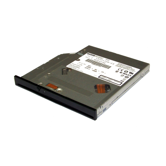
3. CONSTRUCTION 3.1 External Construction (1) Dimensions (a) Height : 12.7mm (excluding the front bezel) (b) Width : 128mm (excluding the front bezel) (c) Depth : 129.4mm (excluding the eject button) (2) Mass : 178g or less (3) Disc clamp system : Ball clamp (4) Loading : Manual loading using the tray... - Page 5 ( ± 0.4 ) (Unit : mm) (Fig. 3.1-1) External view of the drive – 3 –...
-
Page 6: Installation
3.2 Installation (1) Installation direction : Refer to Fig. 3.2-1 (2) Tilt : Refer to Fig. 3.2-1 below. (3) Installation method : The fixing holes in the side of the unit are used. Separate discussions and arrangements are required when the installation holes are not used. -
Page 7: Disc Specification
4. DISC SPECIFICATION 4.1 Applicable Disc Format • CD-DA • CD-ROM Mode 1 • CD-ROM XA Mode 2 (Form 1, Form 2) • Multi-session Photo CD • CD-I • Video CD • Enhanced CD • CD-TEXT • DVD-ROM • DVD-R (General, Authoring) •... -
Page 8: Data Capacity
Recommended as the recordable disc to be used in this drive is a 79-minute disc for 8x speed manufactured by Taiyo Yuden Co., Ltd. (TEAC Part No.: T0006613, CD-R80-BULK). The use of other recordable discs is conditional on mutual understanding between TEAC and specific users. -
Page 9: Performance
5. PERFORMANCE 5.1 Operating Performance (1) Average random access time : 90msec average (CD-ROM, 24x), 110msec average (DVD-ROM, 8x) (2) Disc speed : Refer to 4.2 (3) Data transfer rate (a) Read sustained : 1,545 to 3,600kB/sec (CD-ROM model) 4,469 to 10,816kB/sec (DVD-ROM) (b) Programmed I/O : 16.7MB/sec max (Mode 0 to 4) (c) Multi-word DMA... -
Page 10: Environmental Conditions
6. ENVIRONMENTAL CONDITIONS The environmental conditions as specified here do not include the environmental conditions of the disc. The environmental conditions of the disc should follow the specifications of the applicable disc. (1) Ambient temperature (a) During operation : 5 to 45°C (Surface temperature on the top cover; 5 to 50°C) (b) During non-operation : –20 to 60°C (c) During transportation (packaged) -
Page 11: Reliability
7. RELIABILITY (1) Mean time between failures (MTBF) : 60,000POH or more (the frequency of use should be 10% at normal temperature and humidity) (2) Mean time to repair (MTTR) : 30minutes (3) Loading/ejecting life : 10,000times or more (4) Power ON/OFF life : 60,000 times or more (5) Laser diode life : MTTF 9,000 hours (Duty 50% pulse 83mW, 60°C) -
Page 12: Interface Connector
11. INTERFACE CONNECTOR (1) Connector on the drive : JAE KX15-50KLDLE or equivalent (2) Applicable connector on the host : JAE KX14-50K5D1 or equivalent (3) Pin assignment : Refer to Table 11-1, Fig. 11-1. (Table 11-1) Interface connector pin assignment SIGNAL SIGNAL LOUT... -
Page 13: Audio Interface
12. AUDIO INTERFACE (1) LOUT : Line output of the left channel (unbalanced) (2) ROUT : Line output of the right channel (unbalanced) (3) AGND : Ground of audio line output. For the electrical specification of the line output, refer to 5.2. 13. -
Page 14: Ide Hardware Interface
14. IDE HARDWARE INTERFACE 14.1 Outline (1) Applicable standard ANSI standard : X3T13/1321D (ATA-5) SFFC : SFF-8020i Rev. 2.6 and SFF-8090v3 14.2 Electrical Characteristics The following specifications apply to the interface connector terminal for the IDE signal of the drive. The input signals refer to the signals input to the drive whereas the output signals refer to the signals output from the drive. -
Page 15: Input/Output Signals
(4) Open-drain output signals ( –IOCS16) • Low level : 0 to 0.4VDC (output sink current 12mA) • Maximum output current at high impedance : ±25µA (5) Input signals (–RESET, –DIOW, –DIOR, –CSEL, –DMACK, DA0 to DA2, –CS0, –CS1) (a) Input signal level •... -
Page 16: Interface Timing
(Table 14.3-1) IDE Interface signal summary (Sheet 2 of 2) Signal Description Direction Device address bit 0 Device address bit 1 Device address bit 2 –DMACK DMA acknowledge DMARQ DMA request INTRQ Interupt request –IOCS16 Drive 16 bit I/O –IOR I/O read –HDMARDY DMA ready during Ultra DMA data in bursts... - Page 17 –RESET –DASP –PDIAG Symbol Item Unit µs –HRST pulse width (Fig. 14.4-1) Reset timing (master) –RESET –DASP –PDIAG Symbol Item Unit –DASP assert time –PDIAG assert start (Fig. 14.4-2) Reset timing (slave) – 15 –...
- Page 18 –CS0, CS1 DA0 ~ DA2 –DIOW IORDY DD0 ~ DD15 Symbol Item Unit Address setup time –IOW pulse width Address hold time –IOW interactive pulse width IORDY delay time IORDY pulse width 1,250 Write data setup time Write data hold time Write cycle time (Fig.
- Page 19 –CS0, CS1 DA0 ~ DA2 –DIOR IORDY DD0 ~ DD15 Symbol Item Unit Address setup time –DIOR pulse width Address hold time –DIOR interactive pulse width IORDY delay time IORDY pulse width 1,250 Read data hold time Read cycle time (Fig.
- Page 20 DMARQ –DMACK –DIOW DD0 ~ DD15 –DIOR DD0 ~ DD15 Symbol Item Unit From –DMACK assert to –DMAREQ negate From –DMACK assert to –DIOW low –DIOW, –DIOR pulse width Write data setup time Write data hold time Read data delay time Read data hold time From –DIOW, –DIOR high to –DMACK negate Cycle time...
- Page 21 DMARQ –DMACK –DIOW t41 t42 DD0 ~ DD15 –DIOR DD0 ~ DD15 Symbol Item Unit From –DMACK assert to –DIOW low –DIOW, –DIOR pulse width –DIOW, –DIOR interactive pulse width Write data setup time Write data hold time Read data delay time Read data hold time From –DIOW, –DIOR low to DMARQ negate From –DIOW, –DIOR high to –DMACK negate...
- Page 22 Initiating an Ultra DMA data in burst DMARQ (device) –DMACK (host) STOP (host) −HDMARDY (host) DSTROBE (device) DD(15:0) (device) DA0, DA1, DA2 (host) −CS0, −CS1 (host) Sustained Ultra DMA data in burst DSTROBE (device) DD(15:0) (device) Host pausing an Ultra DMA data in burst DMARQ (device) –DMACK...
- Page 23 Device terminating an Ultra DMA data in burst DMARQ (device) –DMACK (host) STOP (host) −HDMARDY (host) DSTROBE (device) DD(15:0) (device) DA0, DA1, DA2 (host) −CS0, −CS1 (host) Host terminating an Ultra DMA data in burst DMARQ (device) –DMACK (host) STOP (host) −HDMARDY (host)
- Page 24 Symbol Item Unit Unlimited interlock time Setup time/Hold time (to –DMACK ↓ ) Envelope time (–DMACK ↓ to STOP/ –HDMARDY ↓ ) DSTROSE negate start time (STOP/–HDMARDY ↓ to DSTROBE ↓ ) DSTROBE drive delay time (to –DMACK ↓) Output data, release delay time (to –DMACK ↓) Output data, drive start time (to STOP ↓/ –HDMARDY ↓) Valid data, setup time (to DSTROBE edge)
- Page 25 Initiating an Ultra DMA data out burst DMARQ (device) –DMACK (host) STOP (host) −DDMARDY (device) HSTROBE (host) DD(15:0) (host) DA0, DA1, DA2 (host) −CS0, −CS1 (host) Sustained Ultra DMA data out burst HSTROBE (host) t75 t76 DD(15:0) (host) Device pausing an Ultra DMA data out burst DMARQ (device) –DMACK...
- Page 26 Host terminating an Ultra DMA data out burst DMARQ (device) –DMACK (host) STOP (host) −DDMARDY (device) HSTROBE (host) DD(15:0) (host) DA0, DA1, DA2 (host) −CS0, −CS1 (host) Device terminating an Ultra DMA data DMARQ (device) –DMACK (host) STOP (host) −DDMARDY (device) HSTROBE (host)
- Page 27 Symbol Item Unit Unlimited interlock time Setup time/Hold time (to –DMACK ↓ ) Envelope time(–DMACK ↓ to STOP ↓) –DDMARDY drive delay time (to –DMACK ↓) Limited interlock time Data setup time (to –HSTROBE edge/to –DMACK ↑) Data hold time (to HSTORE edge/ to –DMACK ↑) HSTORE cycle time Mode 2 Mode 1...
-
Page 28: Command Set
14.5 COMMAND SET 14.5.1 ATA COMMAND Refer to table 14.5.1-1. (Table 14.5.1-1) ATA COMMAND CODE COMMAND ATAPI SOFT RESET CHECK POWER MODE EXECUTE DRIVE DIAGNOSTIC IDLE IDLE IMMEDIATE ATAPI PKT. ATAPI IDENTIFY DEVICE SET FEATURE SLEEP STANDBY STANDBY IMMEDIATE SERVICE –... -
Page 29: Atapi Command
14.5.2 ATAPI COMMAND Refer to table 14.5.2-1. (Table 14.5.2-1) List of the ATAPI commands (Sheet 1 of 2) CODE COMMAND BLANK CLOSE TRACK/SESSION FORMAT UNIT GET EVENT STATUS NOTIFICATION INQUIRY MECHANISM STATUS MODE SELECT MODE SENSE PAUSE/RESUME PLAY AUDIO (10) PLAY AUDIO (12) PLAY AUDIO MSF PLAY TRACK RELATIVE (10) - Page 30 (Table 14.5.2-1) List of the ATAPI commands (Sheet 2 of 2) CODE COMMAND TEST UNIT READY WRITE (10) WRITE (12) READ DVD STRUCTURE READ FORMATTED CAPACITIES REPORT KEY SEND KEY SET READ AHEAD GET CONFIGURATION GET PERFORMANCE SEND EVENT – 28 –...
-
Page 31: Power Management Specification
15. POWER MANAGEMENT SPECIFICATION This drive has a power management function to reduce power consumption. 15.1 Power Management Modes The drive has the following four power management modes. The transition between these modes is performed by the timer within the drive or a command issued by the host. •... -
Page 32: Active Mode
(1) When the RESET signal is released, the disc detection is performed after self-diagnostics are completed. (2) If the disc is loaded, the mode will switch to the active mode and starting operation will begin. (3) If the disc is not loaded, the mode will switch to the standby mode. (4) Using the power management command (IDLE, IDLE IMMEDIATE, STANDBY, STANDBY IMMEDIATE, SLEEP), the transition from the active mode to the idle, standby or sleep mode, from the idle mode to the standby or sleep mode, or from the standby mode to the idle or sleep mode is possible. -
Page 33: Standby Mode
The transition from the active or standby mode is possible using the power management command (IDLE, IDLE IMMEDIATE). For details, refer to the Software Specification. 15.4 Standby Mode Except for the functions required for the reception of a command, all other functions are in the power save condition. -
Page 34: Safety Of Laser Products
16.2 Safety of Laser Products When selling this unit or a system with this unit to an end user, print the following text in the instruction manual or enclose the separate sheet on which the following text is printed with the instruction manual. This product has been designed and manufactured according to FDA regulations "title 21.
Need help?
Do you have a question about the DW-224E-V and is the answer not in the manual?
Questions and answers