Table of Contents
Advertisement
Quick Links
Advertisement
Table of Contents

Related Manuals for Dukane 28A8941


Summary of Contents for Dukane 28A8941
- Page 1 Progressive Scan Liquid Crystal Projector Model 28A8941/8941A User's Manual...
-
Page 3: Table Of Contents
FEATURES ...2 BEFORE USE ...2 Contents of Package ...2 Part Names...3 Loading the Batteries...5 INSTALLATION ...6 Installation of the Projector and Screen...6 Angle Adjustment ...6 Cabling ...7 Power Connection ...8 Example of System Setup ...8 Plug & Play ...8 OPERATIONS ...9 Power ON ...9... -
Page 4: Features
BEFORE USE Contents of package • NOTE Projector (with Lens Cap) Liquid Crystal Projector CP-X990W USER'S MANUAL Please read this user's manual thoroughly to ensure correct usage through understanding. BEDIENUNGSANLEITUNG Bitte lessen Sie diese Bedienungsanleitung zugunsten der korrekten Bedienung aufmerksam. -
Page 5: Part Names
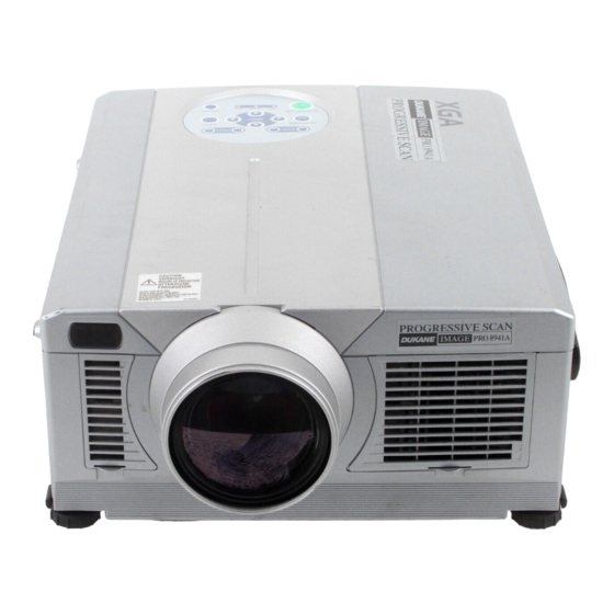
Part Names ZOOM Button KEYSTONE Button STANDBY/ON Button LAMP Indicator POWER Indicator Remote Control Sensor Lens Filter Cover ( Air Filter ) Foot Adjuster Lens Cap Remote Control Sensor Speaker Power Switch AC Inlet (to Power Cord) DVI Terminal S-VIDEO Terminal VIDEO Terminal AUDIO(MONO)/L Terminal... -
Page 6: Remote Control Transmitter
Part Names (continued) STANDBY/ON Button VIDEO Button Disk Pad Used to operate the mouse shift function and left click function. AUTO Button MENU Button MENU SELECT Button Used to click the left mouse button. Button Used to operate the mouse shift function. POSITION Button MAGNIFY Button REMOTE CONTROL TRANSMITTER... -
Page 7: Loading The Batteries
Loading the Batteries CAUTION • Use only the specified batteries with this remote control transmitter. Also, do not mix new and old batteries. This could cause battery cracking or leakage, which could result in fire or personal injury. • When loading the batteries, make sure the plus and minus terminals are correctly oriented as indicated in the remote control transmitter. -
Page 8: Installation
• Please basically use liquid crystal projector at the horizontal position. If you use liquid crystal projector by the lens up position, the lens down position and the side up position, this may cause the heat inside to build up and cause damage. Be especially careful not to install it with ventilation holes blocked. -
Page 9: Cabling
• Before connecting, turn off to all devices to be connected, except for the USB cable. • The cables may have to be used with the core set to the projector side. Use the cables which are included with the projector or specified. -
Page 10: Power Connection
Power Connection CAUTION • Be carful in handling the power cord according to instructions of the accompanying manual "SAFETY INSTRUCTIONS" and this manual. • Connect the power cord firmly. Avoid using a loose, unsound outlet or failed contact. Example of System Setup Computer (desktop type) S-Video Tape... -
Page 11: Operations
OPERATIONS OPERATIONS POWER Indicator FOCUS button Power Switch Power ON Power OFF WARNING • Please read this manual, and the separate “SAFETY INSTRUCTIONS” thoroughly before using the equipment. Always ensure that the equipment is used safely. NOTE STANDBY/ON Button ZOOM button FOCUS button Lens cap ZOOM button... -
Page 12: Basic Operation
Basic Operation Table 3 . Basic Operation Item Select Input Signal ( RGB IN 1 → RGB IN 2 → DVI → VIDEO → S-VIDEO → COMPONENT VIDEO (→ RGB IN 1) Select RGB Input : Press the RGB button. VIDEO/S-VIDEO/COMPONENT VIDEO →... - Page 13 Table 3. Basic Operation (continued) Item VOLUME Volume Adjustment : Press the VOLUME Set/Clear Mute Mode : Press the MUTE button. No sound is heard in the MUTE MUTE mode. Automatic Adjustment at RGB Input : Press the AUTO button. Horizontal position(H.POSIT), vertical position (V.POSIT),clock phase (H.PHASE), and horizontal size(H.SIZE) are automatically adjusted.
-
Page 14: Setup Menu
Setup Menu Table 4. Setup Menu Item Adjustment: Dark BRIGHT Adjustment: Weak CONTRAST Adjustment: Down V POSIT Adjustment: Left H POSIT Adjustment: Left H PHASE • Adjust to eliminate flicker. Adjustment: Small • The image may not be displayed correctly if the horizontal H SIZE size is excessive. -
Page 15: Input Menu
Input Menu Table 5. Input Menu Item Automatic Adjustment at RGB Input: Select the EXECUTE with the Horizontal position (H.POSIT), vertical position (V.POSIT), clock phase (H.PHASE), and horizontal size (H.SIZE) are automatically adjusted. Use with the window at maximum size in the application display. Automatic Adjustment at Video Input: Select the EXECUTE with the AUTO signal type appropriate for the input signal is selected automatically when EXECUTE... -
Page 16: Image Menu
Image Menu Table 6. Image Menu Item Select Blank Screen: Select the screen in case of the BLANK mode with the button.The selected one (MyScreen, ORIGIAL or one colors) is displayed when the BLANK mode is ON. MyScreen is a mode that the customer-customized screen is displayed. This is the BLANK blue screen at the factory setting. -
Page 17: Options Menu
Options Menu Table 7. Options Menu Item VOLUME Volume Adjustment: Reduce VOLUME MENU COLOR Select Menu Background Color: Select with the Operation Start/Stop: Press the LANGUAGE Select Menu Display Language: Select with the Operation Start/Stop: Press the Set AUTO OFF: Set 1~99 minutes with the system automatically enters the standby mode when a signal is not AUTO OFF received for the set time. -
Page 18: No Signal Menu
No Signal Menu Table 8. No Signal Menu Item Volume Adjustment: Reduce VOLUME • When this function is used, audio input is automatically switched to video. The VOLUME audio input can be switched by moving the DISK PAD left and right during the display of the volume adjustment bar. -
Page 19: Maintenance
• Should the lamp burst (accompanied by a big bursting noise), perform ventilation sufficiently, and exercise maximum caution not to inhale any gas out of the projector’s air vent or not to let it enter your eyes or mouth. -
Page 20: Replacing The Lamp
Replacing the Lamp CAUTION • Ensure that screws are tightened properly. Screws not tightened fully may result in injury or accidents. • Do not use the projector with the lamp cover removed. Resetting the Lamp Timer • NOTE ENGLISH-18 ENGLISH-18... -
Page 21: Air Filters
• Do not use the equipment with the air filter removed. • When the air filter is clogged with dust etc. the power supply is switched OFF automatically to prevent the temperature rising inside the projector. Other Maintenance Maintenance Inside the Equipment... -
Page 22: Troubleshooting
TROUBLESHOOTING TROUBLESHOOTING OSD Message Table 9. OSD Message Message CHANGE THE LAMP AFTER REPLACING LAMP, RESET THE LAMP TIME. CHANGE THE LAMP AFTER REPLACING LAMP, RESET THE LAMP TIME. THE POWER WILL TURN OFF AFTER CHANGE THE LAMP AFTER REPLACING LAMP, RESET THE LAMP TIME. -
Page 23: Indicators Message
Indicators Message Table 10. Indicators Message POWER LAMP TEMP indicator indicator indicator Lights Turns off Turns off The Standby mode has been set. orange Blinks Turns off Turns off Warming up. Please wait. green Lights Turns off Turns off ON. Normal operation possible. green Blinks Turns off Turns off Cooling. -
Page 24: Symptom
Turn on the main power switch. Plug the power cord into an AC power outlet. Turn off the projector with the main power switch (set the power switch to [O]), and wait for about 20 minutes. When the equipment has cooled enough, turn power on. -
Page 25: Specifications
Control functions Optional Parts • NOTE Specification Liquid crystal projector 3.3 cm (1.3 type) TFT active matrix 786,432 pixels (1024 horizontal x 768 vertical) Zoom lens F=1.7 ~ 2.3 f=49.0 ~ 64.0 mm 275 W UHB 1.2 W + 1.2W (Stereo) AC100 ~ 120V, 4.7A / AC220 ~ 240V, 2.0A... -
Page 26: Warranty And After-Service
WARRANTY AND AFTER-SERVICE WARRANTY AND AFTER-SERVICE ENGLISH-24 ENGLISH-24... -
Page 27: Dimension Diagram
TECHNICAL TECHNICAL Dimension Diagram Signal Connector Pin Assignment 1. D-sub 15-pin Shrink Connector (RGB IN 1/RGB IN 2/RGB OUT) Pin No Signal Video input Red Video input Green Video input Blue Ground Ground Red Ground Green Ground Blue 2. Digital Receptacle Connector (DVI) Pin No Signal T.M.D.S. -
Page 28: Example Of Computer Signal
Some computers may have multiple display screen modes. Use of some of these modes will not be possible with this projector. • Be sure to check jack type, signal level, timing and resolution before connecting this projector to a computer. - Page 29 Initial set signals The following signals are used for the initial settings. The signal timing of some computer models may be different. In such case, refer to adjust the V.POSIT and H.POSIT of the menu. Back porch b Display interval c Sync a Computer / Horizontal signal timing (µs)
-
Page 30: Usb Mouse
Connection to the Mouse Control 1. PS/2, ADB or Serial Mouse (1) Turn off the projector and computer, and connect the two units with the appropriate cable. For PS/2 mouse control (for IBM and compatible), use the enclosed mouse cable. For others, consult your dealer. -
Page 31: Serial Mouse
ADB Mouse CONTROL Terminal D-sub 15-pin shrink jack Serial Mouse CONTROL Terminal D-sub 15-pin shrink jack USB Mouse USB jack (B type) Projector — DATA DATA Projector Computer DATA Projector SEL0 Computer USB cable ( POWER ON ) Mouse jack... -
Page 32: Communications Setting
RS-232C communication (1) Turn off the projector and computer power supplies and connect with the RS-232C cable. (2) Turn on the computer power supply and, after the computer has started up, turn on the projector power supply. Control jack D-sub 15-pin shrink jack... - Page 33 • Provide an interval of at least 40ms between the response code and any other code. • The projector outputs test data when the power supply is switched ON, and when the lamp is lit. Ignore this data. • Commands are not accepted during warm-up.
-
Page 34: Command Data Chart
Names Operation type Orange Green Blue Purple Blank Color White Black MyScreen ORIGINAL Normal H Inverse Mirror V lnverse H&V Inverse Normal Freeze Freeze Orange Green Blub Menu Color Purple Transparent Gray ORIGINAL Startup MyScreen English Français Deutsch Español Italiano Language Norsk Nederlands... - Page 35 Names Operation type Magnify Increment Decrement Auto off Increment Decrement Brightness Reset Execute Contrast Reset Execute V.Position Reset Execute H.Position Reset Execute H.Size Reset Execute Color Balance R Reset Execute Color Balance B Reset Execute Sharpness Reset Execute Color Reset Execute Tint Reset Execute...
- Page 36 Names Operation type Normal Mute Mute Brightness Increment Decrement Contrast Increment Decrement Color Increment Balance R Decrement Color Increment Balance B Decrement Keystone_V Increment Decrement Increment Keystone_H Decrement 16:9 Aspect Small Default Display Bottom Position at 16 : 9 or Small V.Position Increment Decrement...
- Page 37 Names Operation type Sharpness Increment Decrement Increment Color Decrement Tint Increment Decrement Auto NTSC SECAM Video Format NTSC 4.43 M-PAL N-PAL Video NR Progressive FILM Black 1080i HDTV 1035i Large PinP Size Small Command data chart Header BE EF 06 00 BE EF 06 00 BE EF...
- Page 38 Names Operation type Upper left Upper right bottom left PinP Position bottom right Video PinP Audio ch Video S-Video PinP Input Component Increment FOCUS Decrement Increment Zoom Decrement Sync on G NORMAL WHISPER WHISPER NORMAL CINEMA DYNAMIC GAMMA 6500K TECHNICAL - 12 Command data chart Header BE EF...
-
Page 39: Regulatory Notices
FCC (Federal Communication Commission) equipment provided that the following conditions are met. The cables may have to be used with the core set to the projector side. Use the cables which are included with the projector or specified. CAUTION: Changes or modifications not expressly approved by the party responsible for compliance could void the user’s authority to operate the... - Page 40 DUKANE CORPORATION FIVE-YEAR LIMITED WARRANTY This Dukane projector is warranted to the original purchaser for a period of five (5) years from the original purchase date – in normal operating conditions – against defects in material and workmanship . DUKANE CORPORATION EXPRESSLY DISCLAIMS ALL OTHER WARRANTIES OF MERCHANTABILITY AND FITNESS FOR A PARTICULAR PURPOSE.
- Page 42 Dukane Corporation Audio Visual Products Division 2900 Dukane Drive St. Charles, IL 60174-3395 E-mail: avsales@dukane.com Phone: (630) 584-2300 Orders: (800) 676-2485 Fax: (630) 584-5156 Parts & Service: (800) 676-2487 Fax: (630) 584-0984 Audio Visual Products Part # 401-586-01...
Need help?
Do you have a question about the 28A8941 and is the answer not in the manual?
Questions and answers