Table of Contents
Advertisement
Quick Links
Advertisement
Table of Contents

Related Manuals for Dukane 28A8909


Summary of Contents for Dukane 28A8909
- Page 1 Progressive Scan Liquid Crystal Projector Model 28A8909 User's Manual...
-
Page 11: Table Of Contents
Liquid Crystal Projector USER'S MANUAL USER'S MANUAL Thank you for purchasing this liquid crystal projector. WARNING • Please read the accompanying manual “SAFETY INSTRUCTIONS” and this “USER'S MANUAL” thoroughly to ensure correct usage through understanding. After reading, store this instruction manual in a safe place for future reference. -
Page 12: Features
FEATURES FEATURES This liquid crystal projector is used to project various computer signals as well as NTSC / PAL / SECAM video signals onto a screen. Little space is required for installation and large images can easily be realized. Outstanding Brightness The UHB lamp and high-efficiency optical system assure a high level of brightness. -
Page 13: Part Names
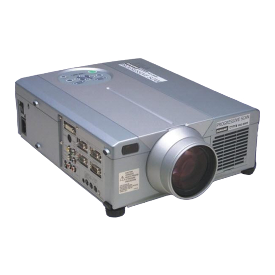
Part Names ZOOM Button MUTE Button STANDBY/ON Button LAMP Indicator POWER Indicator Remote Control Sensor Lens Foot Adjuster Lens Cap Remote Control Sensor Speaker Power Switch AC Inlet (to Power Cord) DIGTAL Terminal S-VIDEO Terminal VIDEO Terminal AUDIO(MONO)/L Terminal AUDIO R Terminal USB Terminal ZOOM FOCUS... -
Page 14: Remote Control Transmitter
• Do not wet the remote control transmitter or place it on any wet object. • Do not place the remote control transmitter close to the cooling fan of the projector. • Do not disassemble the remote control transmitter in case of malfunction. Please bring it to the service station. -
Page 15: Loading The Batteries
Loading the Batteries Install the AA batteries into the remote control transmitter. 1. Remove the battery cover. Push the knob while lifting up the battery cover. 2. Load the batteries. Make sure the plus and minus poles are correctly oriented. 3. -
Page 16: Installation
• Please basically use liquid crystal projector at the horizontal position. If you use liquid crystal projector by the lens up position, the lens down position and the side up position, this may cause the heat inside to build up and become the cause of damage. -
Page 17: Cabling
• Before connecting, turn off to all devices to be connected, except for the USB cable. • The cables may have to be used with the core set to the projector side. Use the cables which are included with the projector or specified. -
Page 18: Power Connection
Plug & Play This projector is VESA DDC 1/2B compatible. Plug & play is possible by connecting to a computer that is VESA DDC (Display Data Channel) compatible. Please use this function by connecting the accessory RGB cable with RGB IN 1 terminal (DDC 1/2B compatible), or by connecting an optional digital RGB cable with DIGITAL terminal (DDC 2B compatible). -
Page 19: Operations
• Except in emergencies, do not turn off unless the POWER indicator is orange as it will reduce the life of the projector lamp. • To prevent any troble, turn on/off the projector when the computer or video tape recorder is OFF. Providing a RS-232C cable is connected, turn on the computer before the projector. -
Page 20: Basic Operation
• Use the remote control transmitter at a distance of approximately 5m from the sensor on the front of the projector, and within a range of 30° left-right. Strong light and obstacles will interfere with operation of the remote control transmitter. - Page 21 Items indicated by (*) may be used from the control panel. Table 3. Basic Operation (continued) Item VOLUME Volume Adjustment : Press the VOLUME Set/Clear Mute Mode : Press the MUTE button. No sound is heard in the MUTE ( MUTE mode.
-
Page 22: Setup Menu
Setup Menu The following adjustments and settings are possible when SETUP is selected at the top of the menu. Part of the Setup menu differs between RGB input and video input. Select an item with the buttons, and start operation. Use the Single menu to reduce menu size (see Table 3, MENU SELECT). -
Page 23: Input Menu
Input Menu The following functions are available when INPUT is selected on the menu. Select an item with the operation with the effective on video input mode only, not on RGB input mode, except in the P.IN P. window on RGB input mode. Table 5. -
Page 24: Image Menu
Image Menu The following adjustments and settings are available when IMAGE is selected on the menu. Select an item with the start operation. Table 6. Image Menu Item Keystone Adjustment: Reduce size of bottom of image KEYSTONE • When this function is activated, the image may not be displayed correctly with some input signals. -
Page 25: Options Menu
Options Menu The following adjustments and settings are available when OPT. is selected on the menu. Select an item with the start operation. The function indicated (**) are effective on video input mode only, not on RGB input mode, except in the P.IN P. window on RGB input mode. -
Page 26: No Signal Menu
No Signal Menu The same adjustments and settings are available as with the Image and Options menus when the MENU button is pressed during display of the “NO INPUT IS DETECTED ON ***” or “SYNC IS OUT OF RANGE ON ***” message while no signal is received. Table 8. -
Page 27: Maintenance
• Do not use the projector with the lamp cover removed. Lamp Life Projector lamps have a finite life. The image will become darker, and hues will become weaker, after a lamp has been used for a long period of time. -
Page 28: Resetting The Lamp Timer
Replacing the Lamp 1. Switch the projector OFF, remove the power cord from the power outlet, and wait at least 45 minutes for the unit to cool. 2. Prepare a new lamp. 3. Check that the projector has cooled sufficiently, and gently turn it upside down. -
Page 29: Air Filter
The air filter should be cleaned as described below at intervals of approximately 100 hours. 1. Switch the projector power supply OFF, and remove the power cord from the power outlet. 2. Clean the air filter with a vacuum cleaner. -
Page 30: Troubleshooting
TROUBLESHOOTING TROUBLESHOOTING OSD Message The messages as described below may appear on the screen at power ON. Take the appropriate measures when such a message appears. Table 9. OSD Messages Message CHANGE THE LAMP AFTER REPLACING LAMP, RESET THE LAMP TIME. CHANGE THE LAMP AFTER REPLACING LAMP, RESET THE LAMP TIME. -
Page 31: Indicators Message
Indicators Message The POWER indicator, LAMP indicator, and TEMP indicator are lit and blank as follows. Take the appropriate measures. Table 10. Indicators Message POWER LAMP TEMP indicator indicator indicator Lights Turns off Turns off The Standby mode has been set. orange Blinks Turns off Turns off Warming up. -
Page 32: Symptom
ENGLISH-22 ENGLISH-22 Possible cause Turn on the main power switch. Plug the power cord into an AC power outlet. Use the projector or remote control transmitter to set. Connect correctly. Connect correctly. Press VOLUME control or display the menu screen and adjust the volume. -
Page 33: Specifications
Optional Parts • NOTE This specifications are subject to change without notice. Specification Liquid crystal projector 3.3 cm (1.3 type) TFT active matrix 786,432 pixels (1024 horizontal x 768 vertical) Zoom lens F=1.7 ~ 2.3 f=49.0 ~ 64.0 mm 250 W UHB 1.2 W + 1.2W (Stereo) -
Page 34: Warranty And After-Service
WARRANTY AND AFTER-SERVICE WARRANTY AND AFTER-SERVICE If a problem occurs with the equipment, first refer to the P.20 “TROUBLESHOOTING” section and run through the suggested checks. If this does not resolve the problem contact your dealer or service company. If repairs are possible, and desirable, they will be charged. ENGLISH-24 ENGLISH-24... -
Page 35: Dimension Diagram
TECHNICAL TECHNICAL Dimension Diagram Signal Connector Pin Assignment 1. D-sub 15-pin Shrink Connector (RGB IN 1/RGB IN 2/RGB OUT) Pin No Signal Video input Red Video input Green Video input Blue Ground Ground Red Ground Green Ground Blue 2. Digital Receptacle Connector (DIGITAL) Pin No Signal T.M.D.S. -
Page 36: Example Of Computer Signal
Some computers may have multiple display screen modes. Use of some of these modes will not be possible with this projector. • Be sure to check jack type, signal level, timing and resolution before connecting this projector to a computer. - Page 37 Initial set signals The following signals are used for the initial settings. The signal timing of some computer models may be different. In such case, refer to adjust the V.POSIT and H.POSIT of the menu. Back porch b Display interval c Sync a Computer / Horizontal signal timing (µs)
- Page 38 Connection to the Mouse Control 1. PS/2, ADB or Serial Mouse (1) Turn off the projector and computer, and connect the two units with the appropriate cable. For PS/2 mouse control (for IBM and compatible), use the enclosed mouse cable. For others, consult your dealer.
-
Page 39: Serial Mouse
ADB Mouse CONTROL Terminal D-sub 15-pin shrink jack Serial Mouse CONTROL Terminal D-sub 15-pin shrink jack USB Mouse USB jack (B type) Projector — DATA DATA Projector Computer DATA Projector SEL0 Computer USB cable ( POWER ON ) Mouse jack... -
Page 40: Communications Setting
RS-232C communication (1) Turn off the projector and computer power supplies and connect with the RS-232C cable. (2) Turn on the computer power supply and, after the computer has started up, turn on the projector power supply. Control jack D-sub 15-pin shrink jack... - Page 41 • Provide an interval of at least 40ms between the response code and any other code. • The projector outputs test data when the power supply is switched ON, and when the lamp is lit. Ignore this data. • Commands are not accepted during warm-up.
-
Page 42: Command Data Chart
Names Operation type Orange Green Blue Blank Color Purple White Black Normal H Inverse Mirror V lnverse H&V Inverse Normal Freeze Freeze Orange Green Blub Menu Color Purple Transparent Gray Turn ON Startup Turn OFF English Français Deutsch Español Italiano Language Norsk Nederlands... - Page 43 Names Operation type Magnify Increment Decrement Auto off Increment Decrement Brightness Reset Execute Contrast Reset Execute V.Position Reset Execute H.Position Reset Execute H.Size Reset Execute Color Balance R Reset Execute Color Balance B Reset Execute Sharpness Reset Execute Color Reset Execute Tint Reset Execute...
- Page 44 Names Operation type Normal Mute Mute Brightness Increment Decrement Contrast Increment Decrement Color Increment Balance R Decrement Color Increment Balance B Decrement Keystone Increment Decrement 16:9 Aspect Small Default Display Bottom Position at 16 : 9 or Small Increment V.Position Decrement Increment H.Position...
- Page 45 Names Operation type Sharpness Increment Decrement Color Increment Decrement Increment Tint Decrement Auto NTSC SECAM Video Format NTSC 4.43 M-PAL N-PAL Video NR Progressive CINEMA Black 1080i HDTV 1035i Large PinP Size Small Command data chart Header BE EF 06 00 F1 72 BE EF 06 00...
- Page 46 Names Operation type Upper left Upper right bottom left PinP Position bottom right Video PinP Audio ch Increment FOCUS Decrement Increment Zoom Decrement Sync on G TECHNICAL - 12 Command data chart Header BE EF 06 00 BE EF 06 00 BE EF 06 00 BE EF...
-
Page 47: Regulatory Notices
FCC (Federal Communication Commission) equipment provided that the following conditions are met. The cables may have to be used with the core set to the projector side. Use the cables which are included with the projector or specified. CAUTION: Changes or modifications not expressly approved by the party responsible for compliance could void the user’s authority to operate the... -
Page 49: Legal Information
LEGAL INFORMATION FIVE-YEAR LIMITED WARRANTY This Dukane LCD projector is warranted to the original purchaser for a period of five (5) years from the original purchase date - in normal use and service - against defects in material and workmanship. DUKANE CORPORATION EXPRESSLY DISCLAIMS ALL OTHER WARRANTIES OF MERCHANTABILITY AND FITNESS FOR A PARTICULAR PURPOSE. - Page 50 Dukane Corporation Audio Visual Products Division 2900 Dukane Drive St. Charles, IL 60174-3395 E-mail: avsales@dukane.com Phone: (630) 584-2300 Orders: (800) 676-2485 Information: (800) 676-2486 Fax: (630) 584-5156 Parts & Service: (800) 676-2487 Fax: (630) 584-0984 Audio Visual Products Part # 401-571-00...
Need help?
Do you have a question about the 28A8909 and is the answer not in the manual?
Questions and answers