Table of Contents
Advertisement
Advertisement
Table of Contents

Related Manuals for Asus F1A75-V PRO


Summary of Contents for Asus F1A75-V PRO
- Page 1 F1A75-V PRO...
- Page 2 Product warranty or service will not be extended if: (1) the product is repaired, modified or altered, unless such repair, modification of alteration is authorized in writing by ASUS; or (2) the serial number of the product is defaced or missing.
-
Page 3: Table Of Contents
Contents Notices ........................vi Safety information ..................... vii About this guide ....................... viii F1A75-V PRO specifications summary ..............x Chapter 1: Product introduction Welcome! ..................... 1-1 Package contents ..................1-1 Special features ..................1-2 1.3.1 Product highlights ................. 1-2 1.3.2 Dual Intelligent Processors 2 –... - Page 4 Updating BIOS ..................... 3-1 3.2.1 ASUS Update utility ..............3-2 3.2.2 ASUS EZ Flash 2 ................. 3-5 3.2.3 ASUS CrashFree BIOS 3 utility ............ 3-6 3.2.4 ASUS BIOS Updater ..............3-7 BIOS setup program ................. 3-10 Main menu ....................3-14 3.4.1 System Language [English] ............
- Page 5 Setup Mode [EZ Mode]............... 3-31 3.8.6 Boot Option Priorities..............3-31 3.8.7 Boot Override ................3-31 Tools menu ....................3-32 3.9.1 ASUS EZ Flash Utility ..............3-32 3.9.2 ASUS O.C. Profile ..............3-32 3.9.3 ASUS SPD Information .............. 3-32 3.10 Exit menu ....................3-33...
-
Page 6: Notices
This class B digital apparatus complies with Canadian ICES-003. ASUS Recycling/Takeback Services ASUS recycling and takeback programs come from our commitment to the highest standards for protecting our environment. We believe in providing solutions for you to be able to responsibly recycle our products, batteries, other components as well as the packaging materials. -
Page 7: Safety Information
Complying with the REACH (Registration, Evaluation, Authorisation, and Restriction of Chemicals) regulatory framework, we published the chemical substances in our products at ASUS REACH website at http://crs.asus.com/english/REACH.htm. DO NOT throw the motherboard in municipal waste. This product has been designed to enable proper reuse of parts and recycling. -
Page 8: About This Guide
Refer to the following sources for additional information and for product and software updates. ASUS websites The ASUS website provides updated information on ASUS hardware and software products. Refer to the ASUS contact information. Optional documentation Your product package may include optional documentation, such as warranty flyers, that may have been added by your dealer. -
Page 9: Conventions Used In This Guide
Conventions used in this guide To ensure that you perform certain tasks properly, take note of the following symbols used throughout this manual. DANGER/WARNING: Information to prevent injury to yourself when trying to complete a task. CAUTION: Information to prevent damage to the components when trying to complete a task. -
Page 10: F1A75-V Pro Specifications Summary
32-bit operating system. ® ** The 64GB maximum memory capacity can be supported with 16GB DIMMs or above. ASUS will update the Memory QVL (Qualified Vendors List) once the DIMMs are available on the market. *** Refer to www.asus.com for the latest Memory QVL (Qualified Vendors List). - Page 11 ASUS Exclusive Features - MemOK! - AI Suite II - AI Charger+ - Anti-Surge Protection - ASUS UEFI BIOS EZ Mode featuring user-friendly graphics interface ASUS Quiet Thermal Solutions - ASUS Fanless Design: Stylish heat pipe solution - ASUS Fan Xpert...
- Page 12 F1A75-V PRO specifications summary ASUS exclusive Intelligent overclocking tools: overclocking - TPU features - Auto Tuning Precision Tweaker 2 - vCore: Adjustable CPU voltage at 0.00625V increment - vDRAM: Adjustable DRAM voltage at 0.01V increment - vFCH: Adjustable FCH voltage at 0.01V increment...
- Page 13 BIOS features 32Mb Flash ROM, UEFI BIOS, PnP, DMI2.0, WfM2.0, ACPI2.0a, SM BIOS 2.6, ASUS EZ Flash 2, ASUS CrashFree BIOS 3 Support DVD contents Drivers ASUS Update ASUS utilities Anti-Virus software (OEM version) Accessories 2 x Serial ATA 6.0Gb/s cables...
-
Page 15: Chapter 1: Product Introduction
® The motherboard delivers a host of new features and latest technologies, making it another standout in the long line of ASUS quality motherboards! Before you start installing the motherboard, and hardware devices on it, check the items in your package with the list below. -
Page 16: Special Features
1.3.2 Dual Intelligent Processors 2 – DIGI+ VRM The world’s first Dual Intelligent Processors from ASUS pioneered the use of two onboard chips - TPU (TurboV Processing Unit) and EPU (Energy Processing Unit). Its new generation of Dual Intelligent Processor 2 with DIGI+ VRM launches power delivery into a digital standard with a programmable microprocessor that perfectly serves power signal, eliminating digital-to-analog conversion lag. -
Page 17: Asus Digital Power Design
ASUS Exclusive Features ASUS TurboV Feel the adrenaline rush of real-time OC-now a reality with the ASUS TurboV. This easy OC tool allows you to overclock without exiting or rebooting the OS; and its user-friendly interface makes overclock with just a few clicks away. Moreover, the ASUS OC profiles in TurboV provides the best O.C. - Page 18 Ai Charger+ ASUS Ai Charger+, the latest Ai Charger* version, brings you to a new level of USB3.0 fast charging experience. With its easy and user-friendly interface, you can not only easily charge iPod, iPhone and iPad, but also BC 1.1** standard mobile devices three times*** as fast as before.
-
Page 19: Asus Mylogo 2
Electronic Magnetic Interference (EMI). ASUS EZ Flash 2 ASUS EZ Flash 2 is a user-friendly utility that allows you to update the BIOS without using a bootable floppy disk or an OS-based utility. ASUS MyLogo 2™... - Page 20 Chapter 1: Product Introduction...
-
Page 21: Chapter 2: Hardware Information
• Before you install or remove any component, ensure that the ATX power supply is switched off or the power cord is detached from the power supply. Failure to do so may cause severe damage to the motherboard, peripherals, or components. ASUS F1A75-V PRO... -
Page 22: Motherboard Overview
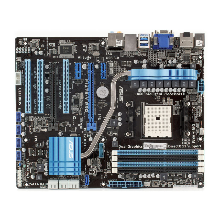
ELED730 MemOK! DRAM_LED ESATA6G _USB3_12 LAN1_USB12 AUDIO PWR_FAN CHA_FAN1 EATXPWR USB3_56 Lithium Cell PCIEX1_1 CMOS Power ASM1061 8111E PCIEX16_1 SATA6G_E1 F1A75-V PRO PCIEX1_2 ® Super PCI1 A75 FCH PCIEX16_2 PCI2 32Mb BIOS ALC892 PCI3 SB_PWR SPDIF_OUT USB78 USB910 USB56 PANEL... -
Page 23: Layout Contents
15. Clear RTC RAM (3-pin CLRTC) 2-17 16. USB connectors (10-1 pin USB78, USB910, USB34, USB56) 2-29 17. Serial port connector (10-1 pin COM1) 2-28 18. Front panel audio connector (10-1 pin AAFP) 2-31 19. Digital audio connector (4-1 pin SPDIF_OUT) 2-28 ASUS F1A75-V PRO... -
Page 24: Placement Direction
Place nine screws into the holes indicated by circles to secure the motherboard to the chassis. DO NOT overtighten the screws! Doing so can damage the motherboard. Place this side towards the rear of the chassis. F1A75-V PRO Chapter 2: Hardware information... -
Page 25: Accelerated Processing Unit (Apu)
Press the lever sideways to unlock the socket, then lift it up to a 90º angle. Socket lever Ensure that the socket lever is lifted up to a 90º angle. Otherwise, the APU will not fit in completely. ASUS F1A75-V PRO... - Page 26 Position the APU above the socket such that the APU corner with the gold triangle matches the socket corner with a small triangle. Carefully insert the APU into the socket until it fits in place. Gold triangle Small triangle When the APU is in place, push down the socket lever to secure the APU.
-
Page 27: Installing The Cpu Heatsink And Fan
Retention module base Your boxed CPU heatsink and fan assembly should come with installation instructions for the CPU, heatsink, and the retention mechanism. If the instructions in this section do not match the CPU documentation, follow the latter. ASUS F1A75-V PRO... - Page 28 Attach one end of the retention bracket to the retention module base. Align the other end of the retention bracket to the retention module base. A clicking sound denotes that the retention bracket is in place. Ensure that the fan and heatsink assembly perfectly fits the retention mechanism module base, otherwise you cannot snap the retention bracket...
- Page 29 CPU_FAN. CPU_FAN F1A75-V PRO • Do not forget to connect the CPU fan connector! Hardware monitoring errors can occur if you fail to plug this connector. • This connector is backward compatible with old 3-pin CPU fan. ASUS F1A75-V PRO...
-
Page 30: System Memory
The figure illustrates the location of the DDR3 DIMM sockets: F1A75-V PRO F1A75-V PRO 240-pin DDR3 DIMM sockets Recommended memory configurations One DIMM: Install one memory module in any slot as a single-channel operation. -
Page 31: Memory Configurations
3.5 Ai Tweaker menu for manual memory frequency adjustment. • For system stability, use a more efficient memory cooling system to support a full memory load (4 DIMMs) or overclocking condition. • Visit the ASUS website for the latest QVL. ASUS F1A75-V PRO 2-11... -
Page 32: Installing A Dimm
2.4.3 Installing a DIMM Ensure to unplug the power supply before adding or removing DIMMs or other system components. Failure to do so may cause severe damage to both the motherboard and the components. DIMM notch Unlock a DIMM socket by pressing the retaining clips outward. -
Page 33: Expansion Slots
When using PCI cards on shared slots, ensure that the drivers support “Share IRQ” or that the cards do not need IRQ assignments. Otherwise, conflicts will arise between the two PCI groups, making the system unstable and the card inoperable. Refer to the table on the next page for details. ASUS F1A75-V PRO 2-13... -
Page 34: Interrupt Assignments
2.5.3 Interrupt assignments Standard interrupt assignments Priority Standard function System Timer Keyboard Controller – Redirect to IRQ#9 Communications Port (COM1)* IRQ Holder for PCI Steering* Reserved Reserved System CMOS/Real Time Clock IRQ Holder for PCI Steering* IRQ Holder for PCI Steering* IRQ Holder for PCI Steering* PS/2 Keyboard and Mouse Numeric Data Processor... -
Page 35: Pci Slots
PCI slot 1 PCI slot 2 PCIe 2.0 x1_2 slot PCI slot 3 PCIe 2.0 x16_2 slot (black, at x 4 link) PCIe 2.0 x1_1 slot PCIe 2.0 x16_1 slot (blue, at x 16 link) ASUS F1A75-V PRO 2-15... - Page 36 PCI Express operating mode VGA configuration PCIe x16_1 PCIe x16_2 Single VGA/PCIe card x16 (Recommended for single VGA card) Dual VGA/PCIe card • In single VGA card mode, use first the PCIe 2.0 x16_1 slot (blue) for a PCI Express x16 graphics card to get better performance.
-
Page 37: Jumper
• You do not need to clear the RTC when the system hangs due to overclocking. For system failure due to overclocking, use the C.P.R. feature. Shut down and reboot the system so the BIOS can automatically reset parameter settings to default values. ASUS F1A75-V PRO 2-17... -
Page 38: Onboard Switches
Onboard switches Onboard switches allow you to fine-tune performance when working on a bare or open- case system. This is ideal for overclockers and gamers who continually change settings to enhance system performance. TPU switch This switch allows you to enable or disable the TPU function. •... - Page 39 • You may change the EPU settings in the EPU application, change the BIOS settings, and enable the EPU function at the same time. However, the system will use the last setting you have made. ASUS F1A75-V PRO 2-19...
- Page 40 BIOS default settings. A message will appear during POST reminding you that the BIOS has been restored to its default settings. • We recommend that you download and update to the latest BIOS version from the ASUS website at www.asus.com after using the MemOK! function.
-
Page 41: Connectors
• DO NOT insert a different connector to the external SATA port. • To use hot plugging, set the SATA Port1 - Port4 item in the BIOS to [AHCI]. Refer to 3.4.2 SATA Configuration for details. ASUS F1A75-V PRO 2-21... -
Page 42: Lan Port Led Indications
* LAN port LED indications ACT/LINK SPEED Activity Link LED Speed LED Status Description Status Description No link 10 Mbps connection ORANGE Linked ORANGE 100 Mbps connection BLINKING Data activity GREEN 1 Gbps connection LAN port ** Audio 2, 4, 6, or 8-channel configuration Headset Port 4-channel... - Page 43 Playback software CyberLink PowerDVD 9 Best resolution File format Windows XP Windows Vista Windows 7 Non-protected clips 1920 x 1080p 1920 x 1080p 1920 x 1080p Blu-ray 1920 x 1080p 1920 x 1080p 1920 x 1080p ASUS F1A75-V PRO 2-23...
- Page 44 Troubleshooting on HDTV overscaling or underscaling: If your desktop is extending beyond the viewable display area or the desktop or image is not filling the entire display area while using the onboard HDMI out port and the HDMI cable, you can resize the desktop appearing on your HDTV screen.
-
Page 45: Audio I/O Connections
2.8.2 Audio I/O connections Audio I/O ports Connect to Headphone and Mic Connect to Stereo / 2.1-channel Speakers ASUS F1A75-V PRO 2-25... - Page 46 Connect to 4.1 channel Speakers Connect to 5.1 channel Speakers Connect to 7.1 channel Speakers 2-26 Chapter 2: Hardware information...
-
Page 47: Internal Connectors
The Serial ATA RAID feature is available only if you are using Windows ® XP SP3 or later version. • When using hot-plug and NCQ, set the type of the SATA connectors to [AHCI] in the BIOS. See section 3.4.2 SATA Configuration for details. ASUS F1A75-V PRO 2-27... - Page 48 Serial port connector (10-1 pin COM1) This connector is for a serial (COM) port. Connect the serial port module cable to this connector, then install the module to a slot opening at the back of the system chassis. The COM module is purchased separately. Digital audio connector (4-1 pin SPDIF_OUT) This connector is for an additional Sony/Philips Digital Interface (S/PDIF) port.
- Page 49 Never connect a 1394 cable to the USB connectors. Doing so will damage the motherboard! You can connect the front panel USB cable to the ASUS Q-Connector (USB, blue) first, and then install the Q-Connector (USB) to the USB connector onboard if your chassis supports front panel USB ports.
- Page 50 • The CPU_FAN connector supports the CPU fan of maximum 2A (24 W) fan power. • Only the 4-pin CPU_FAN and 4-pin CHA_FAN connectors support the ASUS Fan Xpert feature. • If you install two VGA cards, we recommend that you plug the rear chassis fan cable to the motherboard connector labeled CHA_FAN for better thermal environment.
- Page 51 Front Panel Select item in the BIOS setup to [HD Audio]; if you want to connect an AC'97 front panel audio module to this connector, set the item to [AC 97]. By default, this connector is set to [HD]. Refer to 3.6.3 Onboard Devices Configuration for details. ASUS F1A75-V PRO 2-31...
- Page 52 • If you are uncertain about the minimum power supply requirement for your system, refer to the Recommended Power Supply Wattage Calculator at http://support.asus. com/PowerSupplyCalculator/PSCalculator.aspx?SLanguage=en-us for details. • If you want to use two high-end PCI Express x16 cards, use a PSU with 1000W power or above to ensure the system stability.
- Page 53 ATX power button/soft-off button (2-pin PWRSW) This connector is for the system power button. • Reset button (2-pin RESET) This 2-pin connector is for the chassis-mounted reset button for system reboot without turning off the system power. ASUS F1A75-V PRO 2-33...
-
Page 54: Asus Q-Connector (System Panel)
2.8.4 ASUS Q-Connector (system panel) Use the ASUS Q-Connector to connect/disconnect the chassis front panel cables. To install the ASUS Q-Connector: Connect the front panel cables to the ASUS Q-Connector. Refer to the labels on the Q-Connector to know the detailed pin definitions, and then match them to their respective front panel cable labels. -
Page 55: Onboard Leds
DRAM LED checks the DRAM in sequence during motherboard booting process. If an error is found, the LED next to the error device will continue lighting until the problem is solved. This user-friendly design provides an intuitional way to locate the root problem within a second. ASUS F1A75-V PRO 2-35... - Page 56 TPU LED The TPU LED lights when the TPU switch is turned to Enable. EPU LED The EPU LED lights when the EPU switch is turned to Enable. 2-36 Chapter 2: Hardware information...
-
Page 57: Starting Up For The First Time
BIOS setting. Pressing the power switch for more than four seconds lets the system enter the soft-off mode regardless of the BIOS setting. Refer to section 3.7 Power menu in Chapter 3 for details. ASUS F1A75-V PRO 2-37... - Page 58 2-38 Chapter 2: Hardware information...
-
Page 59: Chapter 3: Bios Setup
Refer to the corresponding sections for details on these utilities. Save a copy of the original motherboard BIOS file to a USB flash disk in case you need to restore the BIOS in the future. Copy the original motherboard BIOS using the ASUS Update utility. -
Page 60: Asus Update Utility
3.2.1 ASUS Update utility The ASUS Update is a utility that allows you to manage, save, and update the motherboard BIOS in Windows environment. The ASUS Update utility allows you to: ® • Save the current BIOS file • Download the latest BIOS file from the Internet •... - Page 61 Follow the onscreen instructions to complete the update process. Updating the BIOS through a BIOS file To update the BIOS through a BIOS file: From the ASUS Update screen, select Update BIOS from file, and then click Next. ASUS F1A75-V PRO...
- Page 62 • The screenshots in this section are for reference only. The actual BIOS information vary by models. • Refer to the software manual in the support DVD or visit the ASUS website at www.asus.com for detailed software configuration. Chapter 3: BIOS setup...
-
Page 63: Asus Ez Flash 2
3.2.2 ASUS EZ Flash 2 The ASUS EZ Flash 2 feature allows you to update the BIOS without using an OS-based utility. Before you start using this utility, download the latest BIOS file from the ASUS website at www.asus.com. To update the BIOS using EZ Flash 2: Insert the USB flash disk that contains the latest BIOS file to the USB port. -
Page 64: Asus Crashfree Bios 3 Utility
3.2.3 ASUS CrashFree BIOS 3 utility The ASUS CrashFree BIOS 3 utility is an auto recovery tool that allows you to restore the BIOS file when it fails or gets corrupted during the updating process. You can restore a corrupted BIOS file using the motherboard support DVD or a USB flash drive that contains the BIOS file. -
Page 65: Asus Bios Updater
3.2.4 ASUS BIOS Updater The ASUS BIOS Updater allows you to update BIOS in DOS environment. This utility also allows you to copy the current BIOS file that you can use as a backup when the BIOS fails or gets corrupted during the updating process. - Page 66 The BIOS Updater backup screen appears indicating the BIOS backup process. When BIOS backup is done, press any key to return to the DOS prompt. ASUSTek BIOS Updater for DOS V1.07 Current ROM Update ROM BOARD: F1A75-V PRO BOARD: Unknown VER: 0209 VER:...
- Page 67 Select the Load Optimized Defaults item under the Exit menu. Refer to section 2.9 Exit menu for details. • Ensure to connect all SATA hard disk drives after updating the BIOS file if you have disconnected them. ASUS F1A75-V PRO...
-
Page 68: Bios Setup Program
BIOS setup program Use the BIOS Setup program to update the BIOS or configure its parameters. The BIOS screens include navigation keys and brief online help to guide you in using the BIOS Setup program. Entering BIOS Setup at startup To enter BIOS Setup at startup: •... -
Page 69: Bios Menu Screen
Selects the boot device priority • The boot device options vary depending on the devices you installed to the system. • The Boot Menu(F8) button is available only when the boot device is installed to the system. ASUS F1A75-V PRO 3-11... -
Page 70: Advanced Mode
The Advanced Mode provides advanced options for experienced end-users to configure the BIOS settings. The figure below shows an example of the Advanced Mode. Refer to the following sections for the detailed configurations. To access the EZ Mode, click Exit, then select ASUS EZ Mode. Back button Menu items... -
Page 71: Menu Items
You cannot select an item that is not user-configurable. A configurable field is highlighted when selected. To change the value of a field, select it and press <Enter> or click on it to display a list of options. ASUS F1A75-V PRO 3-13... -
Page 72: Main Menu
Main menu The Main menu screen appears when you enter the Advanced Mode of the BIOS Setup program. The Main menu provides you an overview of the basic system information, and allows you to set the system date, time, language, and security settings. EFI BIOS Utility - Advanced Mode Exit Ai Tweaker... -
Page 73: Administrator Password
To clear the user password, follow the same steps as in changing a user password, but press <Enter> when prompted to create/confirm the password. After you clear the password, the User Password item on top of the screen shows Not Installed. ASUS F1A75-V PRO 3-15... -
Page 74: Ai Tweaker Menu
Ai Tweaker menu The Ai Tweaker menu items allow you to configure overclocking-related items. Be cautious when changing the settings of the Ai Tweaker menu items. Incorrect field values can cause the system to malfunction. The configuration options for this section vary depending on the CPU and DIMM model you installed on the motherboard. -
Page 75: Ai Overclock Tuner [Auto]
DRAM O.C. profile, which applies different settings to DRAM frequency, DRAM timing and DRAM voltage. Configuration options: [DDR3-1600MHz 9-9-9-24 1.65V] [DDR3-1800MHz 9-9-9-24 1.65V] [DDR3-1866MHz 9-9-9-24 1.65V] [DDR3-2000MHz 9-9- 9-24 1.65V] [DDR3-2133MHz 9-9-9-24 1.65V] [DDR3-2200MHz 9-9-9-24 1.65V] [DDR3- 2400MHz 9-9-9-24 1.65V] ASUS F1A75-V PRO 3-17... -
Page 76: Memory Frequency [Auto]
3.5.2 Memory Frequency [Auto] Allows you to set the memory operating frequency. Configuration options: [Auto] [DDR3-1066MHz] [DDR3-1333MHz] [DDR3-1600MHz] [DDR3-1866MHz] Selecting a very high memory frequency may cause the system to become unstable! If this happens, revert to the default setting. 3.5.3 APU Multiplier [Auto] Allows you to set the ratio between the CPU Core Clock and the FSB Frequency. -
Page 77: Dram Voltage [Auto]
1.1V Voltage, 1.1Vsb Voltage, APU1.2V Voltage, and VDDA Voltage items are labeled in different color, indicating the risk levels of high voltage settings. • The system may need better cooling system to work stably under high voltage settings. ASUS F1A75-V PRO 3-19... -
Page 78: Digi+Vrm
VRM efficiency. [Standard] Proceeds to phase control depending on the CPU loading. [Optimized] Loads the ASUS optimized phase tuning profile. [Extreme] Proceeds to the full phase mode. [Manual Adjustment] Allows manual adjustment. -
Page 79: Apu Spread Spectrum [Auto]
Do not remove the thermal module while changing the DIGI+VRM parameters. The thermal conditions should be monitored. 3.5.14 APU Spread Spectrum [Auto] [Auto] Automatic configuration. [Disabled] Enhances the PCIE overclocking ability. [Enabled] Sets to [Enabled] for EMI control. ASUS F1A75-V PRO 3-21... -
Page 80: Advanced Menu
Advanced menu The Advanced menu items allow you to change the settings for the CPU and other system devices. Be cautious when changing the settings of the Advanced menu items. Incorrect field values can cause the system to malfunction. EFI BIOS Utility - Advanced Mode Ai Tweaker Advanced Monitor... -
Page 81: Sata Configuration
S.M.A.R.T. Status Check [Enabled] S.M.A.R.T. (Self-Monitoring, Analysis and Reporting Technology) is a monitor system. When read/write of your hard disk errors occur, this feature allows the hard disk to report warning messages during the POST. Configuration options: [Enabled] [Disabled] ASUS F1A75-V PRO 3-23... -
Page 82: Usb Configuration
3.6.3 USB Configuration The items in this menu allow you to change the USB-related features. The USB Devices item shows the auto-detected values. If no USB device is detected, the item shows None. Legacy USB Support [Enabled] [Enabled] Enables the support for USB devices on legacy operating systems (OS). [Disabled] The USB devices can be used only for the BIOS setup program. -
Page 83: Onboard Devices Configuration
Allows you to enable or disable the serial port (COM). Configuration options: [Ena bled] [Disabled] Change Settings [IO=3F8h; IRQ=4] Allows you to select the Serial Port base address. Configuration options: [IO=3F8h; IRQ=4] [IO=2F8h; IRQ=3] [IO=3E8h; IRQ=4] [IO=2E8h; IRQ=3] ASUS F1A75-V PRO 3-25... -
Page 84: Apm
3.6.6 Restore AC Power Loss [Power Off] [Power On] The system goes into on state after an AC power loss. [Power Off] The system goes into off state after an AC power loss. [Last State] The system goes into either off or on state, whatever the system state was before the AC power loss. -
Page 85: Monitor Menu
This item appears only when you enable the CPU Q-Fan Control feature and allows you to disable or set the CPU fan warning speed. Configuration options: [Ignore] [200RPM] [300 RPM] [400 RPM] [500 RPM] [600 RPM] ASUS F1A75-V PRO 3-27... -
Page 86: Chassis Q-Fan Control [Disabled]
CPU Fan Profile [Standard] This item appears only when you enable the CPU Q-Fan Control feature and allows you to set the appropriate performance level of the CPU fan. [Standard] Sets to [Standard] to make the CPU fan automatically adjust depending on the CPU temperature. -
Page 87: Cpu Voltage, 3.3V Voltage, 5V Voltage, 12V Voltage
The onboard hardware monitor automatically detects the voltage output through the onboard voltage regulators. Select Ignore if you do not want to detect this item. 3.7.6 Anti Surge Support [Enabled] This item allows you to enable or disable the Anti Surge function. Configuration options: [Disabled] [Enabled] ASUS F1A75-V PRO 3-29... -
Page 88: Boot Menu
[Disabled] Disables the full screen logo display feature. Set this item to [Enabled] to use the ASUS MyLogo 2™ feature. Post Report [5 sec] This item appears only when the Full Screen Logo item is set to [Disabled] and allows you to set the waiting time for the system to display the post report. -
Page 89: Option Rom Messages [Force Bios]
• To select the boot device during system startup, press <F8> when ASUS Logo appears. • To access Windows OS in Safe Mode, press <F8> after POST. -
Page 90: Tools Menu
> ASUS SPD Information 3.9.1 ASUS EZ Flash Utility Allows you to run ASUS EZ Flash 2. Press [Enter] to launch the ASUS EZ Flash 2 screen. For more details, see section 2.1.2 ASUS EZ Flash 2. 3.9.2 ASUS O.C. Profile This item allows you to store or load multiple BIOS settings. -
Page 91: Exit Menu
This option allows you to enter the EZ Mode screen. Launch EFI Shell from filesystem device This option allows you to attempt to launch the EFI Shell application (shellx64.efi) from one of the available devices that have a filesystem. ASUS F1A75-V PRO 3-33... - Page 92 3-34 Chapter 3: BIOS setup...
-
Page 93: Chapter 4: Software Support
The contents of the support DVD are subject to change at any time without notice. Visit the ASUS website at www.asus.com for updates. 4.2.1 Running the support DVD Place the support DVD into the optical drive. -
Page 94: Obtaining The Software Manuals
The software manual files are in Portable Document Format (PDF). Install the Adobe ® Acrobat Reader from the Utilities menu before opening the files. ® Click the Manual tab. Click ASUS Motherboard Utility Guide from the manual list on the left. The Manual folder of the support DVD appears. Double-click the folder of your selected software. -
Page 95: Software Information
4.3.1 ASUS AI Suite II ASUS AI Suite II is an all-in-one interface that integrates several ASUS utilities and allows users to launch and operate these utilities simultaneously. Installing AI Suite II To install AI Suite II on your computer: Place the support DVD to the optical drive. -
Page 96: Digi+ Vrm
4.3.2 DIGI+ VRM ASUS DIGI+ VRM allows you to adjust VRM voltage and frequency modulation to enhance reliability and stability. It also provides the highest power efficiency, generating less heat to longer component lifespan and minimize power loss. After installing AI Suite II from the motherboard support DVD, launch DIGI+ VRM by clicking Tool >... - Page 97 • The actual performance boost may vary depending on your CPU and DRAM specification. • Do not remove the thermal module. The thermal conditions should be monitored. ASUS F1A75-V PRO...
- Page 98 VRM efficiency. Standard: Phase control based on CPU • command • Optimized: ASUS optimized phase tuning profile • Extreme: Full phase mode • Manual Adjustment: Phase number adjusted by current(A) step • Set Manual Adjustment to faster phase response to increase system performance or to slower phase response to increase CPU power efficiency.
-
Page 99: Turbov Evo
4.3.3 TurboV EVO ASUS TurboV EVO introduces TurboV that allows you to manually adjust the CPU frequency and related voltages as well as Auto Tuning function that offers automatic and easy overlocking and system level up. After installing AI Suite II from the motherboard support DVD, launch TurboV EVO by clicking Tool >... -
Page 100: Cpu Ratio
Using Advanced Mode Click More Settings, and then click the Advanced Mode tab to adjust the advanced voltage settings. Advanced mode Voltage Target values Adjustment bars Undoes all changes Current values without applying Applies all changes Click to restore immediately all start-up settings CPU Ratio... -
Page 101: Auto Tuning
Auto Tuning ASUS TurboV EVO includes two auto tuning modes, providing the most flexible auto-tuning options. • The overclocking result varies with the CPU model and the system configuration. • To prevent overheating from damaging the motherboard, a better thermal environment is strongly recommended. - Page 102 3. TurboV automatically overclocks the CPU and memory and restarts the system. After re-entering Windows, a message appears indicating the current overclocking result. To keep the result, click Stop. 4. If you did not click Stop in the previous step, TurboV automatically starts further system overclocking and stability test.
-
Page 103: Epu
*• Select From EPU Installation to show the CO2 that has been reduced since you installed EPU. *• Select From the Last Reset to show the total CO2 that has been reduced since you click the Clear button ASUS F1A75-V PRO 4-11... -
Page 104: Fan Xpert
4.3.5 FAN Xpert Fan Xpert intelligently allows you to adjust both the CPU and chassis fan speeds according to different ambient temperatures caused by different climate conditions in different geographic regions and your PC’s system loading. The built-in variety of useful profiles offer flexible controls of fan speed to achieve a quiet and cool environment. -
Page 105: Probe Ii
The Preference tab allows you to customize the time interval of sensor alerts, or change the temperature unit. Saves your configuration Loads your saved Applies your Loads the default configuration changes threshold values for each sensor ASUS F1A75-V PRO 4-13... -
Page 106: Ai Charger
4.3.7 Ai Charger+ Battery Charging Version 1.1 (BC 1.1), a USB Implementers Forum (USB-IF) certified USB charging function, is designed to make USB charging faster than the standard USB devices. If your USB device supports the BC 1.1 function*, when you connect your USB device to your system, the system automatically detects your USB device and starts a fast USB charging. -
Page 107: Raid Configurations
With the RAID 10 configuration you get all the benefits of both RAID 0 and RAID 1 configurations. Use four new hard disk drives or use an existing drive and three new drives for this setup. ASUS F1A75-V PRO 4-15... -
Page 108: Installing Serial Ata Hard Disks
4.4.2 Installing Serial ATA hard disks The motherboard supports Serial ATA hard disk drives. For optimal performance, install identical drives of the same model and capacity when creating a disk array. To install the SATA hard disks for a RAID configuration: Install the SATA hard disks into the drive bays. -
Page 109: Amd ® Option Rom Utility
The RAID BIOS setup screens shown in this section are for reference only, and may not exactly match the items on your screen. To create a RAID volume using more than four hard disk drives, ensure that the SATA connectors 5/6 are set to [RAID] mode. ASUS F1A75-V PRO 4-17... -
Page 110: Creating A Raid Volume
Creating a RAID volume To create a RAID volume: In the Main Menu, press <2> to enter the LD View / LD Define Menu function. Press <Ctrl> + <C>, and the following screen appears. Option ROM Utility (c) 2009 Advanced Micro Devices, Inc. [ LD Define Menu ] LD No LD Name... -
Page 111: Deleting A Raid Configuration
LD Name RAID Mode Capacity(GB) xxxxx RAID 0 157.99 Strip Block 64 KB Cache Mode WriteThru [ Drives Assignments ] Port:ID Drive Model Capabilities Capacity(GB) 01:00 xxxxxxxxx xxxxxxx xxxxxx 02:00 xxxxxxxxx xxxxxxx xxxxxx Any Key To Continue..ASUS F1A75-V PRO 4-19... -
Page 112: Creating A Raid Driver Disk
Creating a RAID driver disk A floppy disk with the RAID driver is required when installing Windows XP operating system ® on a hard disk drive that is included in a RAID set. For Windows Vista or later operating ® systems, use either a USB flash drive with the RAID driver or the support DVD. -
Page 113: Installing The Raid Driver During Windows ® Os Installation
Follow the succeeding screen instructions to complete the installation. Before loading the RAID driver from a USB flash drive, you have to use another computer to copy the RAID driver from the support DVD to the USB flash drive. ASUS F1A75-V PRO 4-21... -
Page 114: Using A Usb Floppy Disk Drive
4.5.4 Using a USB floppy disk drive Due to OS limitation, Windows XP may not recognize the USB floppy disk drive when you ® install the RAID driver from a floppy disk during the OS installation. To solve this issue, add the USB floppy disk drive’s Vendor ID (VID) and Product ID (PID) to the floppy disk containing the RAID driver. - Page 115 “PCI\VEN_1002&DEV_4391&CC_0106”,”ahcix86” id= “PCI\VEN_1002&DEV_4393&CC_0104”,”ahcix86” id= “USB\VID_03EE&PID_6901”, “usbstor” [HardwareIds.SCSI.Napa_amd64_ahci] id= “PCI\VEN_1002&DEV_4392&CC_0104”,”ahcix64” id= “PCI\VEN_1002&DEV_4391&CC_0106”,”ahcix64” id= “PCI\VEN_1002&DEV_4393&CC_0104”,”ahcix64” id= “USB\VID_03EE&PID_6901”, “usbstor” Add the same line to both sections. The VID and PID vary with different vendors. Save and exit the file. ASUS F1A75-V PRO 4-23...
- Page 116 4-24 Chapter 4: Software support...
-
Page 117: Chapter 5: Multiple Gpu Technology Support
For Windows XP, go to Control Panel > Add/Remove Programs. For Windows Vista / 7, go to Control Panel > Programs and Features. Select your current graphics card drivers. For Windows XP, select Add/Remove. For Windows Vista / 7, select Uninstall. Turn off your computer. ASUS F1A75-V PRO... -
Page 118: Installing Two Crossfirex™ Graphics Cards
5.1.3 Installing two CrossFireX™ graphics cards The following pictures are for reference only. The graphics cards and the motherboard layout may vary with models, but the installation steps remain the same. Prepare two CrossFireX-ready graphics cards. Insert the two graphics card into the PCIEX16 slots. -
Page 119: Installing The Device Drivers
In the Catalyst Control Center window, click Graphics Settings > CrossFireX > Configure. From the Graphics Adapter list, select the graphics card to act as the display GPU. Select Enable CrossFireX. Click Apply, and then click OK to exit the window. ASUS F1A75-V PRO... -
Page 120: Amd ® Dual Graphics Technology
Dual Graphics technology ® The motherboard supports the AMD Dual Graphics technology that allows you to install ® multi-graphics processing units (GPU) CrossFireX cards. 5.2.1 System requirements Before using AMD Dual Graphics, ensure that your system meets the following basic requirements: •... -
Page 121: Using The Amd ® Catalyst ® Control Center
Center from the shortcut menu. The AMD CATALYST Control Center screen appears. Click Graphics Settings > CrossFire™, then clear the Enable CrossFire™ check box. When a confirmation message pops up, click Yes. The screen blacks out for about one minute. Click OK. ASUS F1A75-V PRO... - Page 122 Right-click on the Windows desktop, ® then click Personalize from the shortcut menu. Click Display Settings. Select [Default Monitor] on ATI Radeon HD 4250 Graphics, then select the check boxes of This is my main monitor and Extend the desktop onto this monitor. Click OK, and then Yes from the confirmation window.
-
Page 123: Asus Contact Information
+1-510-739-3777 +1-510-608-4555 Web site usa.asus.com Technical Support Telephone +1-812-282-2787 Support fax +1-812-284-0883 Online support support.asus.com ASUS COMPUTER GmbH (Germany and Austria) Address Harkort Str. 21-23, D-40880 Ratingen, Germany +49-2102-959911 Web site www.asus.de Online contact www.asus.de/sales Technical Support Telephone (Component) +49-1805-010923*...
Need help?
Do you have a question about the F1A75-V PRO and is the answer not in the manual?
Questions and answers