Table of Contents
Advertisement
Quick Links
Advertisement
Table of Contents

Related Manuals for Asus F1A75-I DELUXE


Summary of Contents for Asus F1A75-I DELUXE
- Page 1 F1A75-I DELUXE...
- Page 2 Product warranty or service will not be extended if: (1) the product is repaired, modified or altered, unless such repair, modification of alteration is authorized in writing by ASUS; or (2) the serial number of the product is defaced or missing.
-
Page 3: Table Of Contents
Contents Notices ......................vi Safety information ..................vii About this guide ..................viii F1A75-I DELUXE specifications summary ..........ix Chapter 1: Product introduction Welcome! ..................1-1 Package contents ................. 1-1 Special features ................1-1 1.3.1 Product highlights ............1-1 1.3.2 Dual Intelligent Processors 2 –... - Page 4 Managing and updating your BIOS ..........2-1 2.1.1 ASUS Update utility ............2-1 2.1.2 ASUS EZ Flash 2 ............2-2 2.1.3 ASUS CrashFree BIOS 3 utility ........2-3 2.1.4 ASUS BIOS Updater ............2-4 BIOS setup program ..............2-7 Main menu .................. 2-11 2.3.1 System Language [English] ...........2-11...
- Page 5 Setup Mode [EZ Mode] ..........2-26 2.7.6 Boot Option Priorities ............ 2-26 2.7.7 Boot Override ..............2-26 Tools menu ................. 2-27 2.8.1 ASUS EZ Flash 2 Utility ..........2-27 2.8.2 ASUS O.C. Profile ............2-27 2.8.3 ASUS SPD Information ..........2-27 Exit menu ..................2-28...
-
Page 6: Notices
This class B digital apparatus complies with Canadian ICES-003. ASUS Recycling/Takeback Services ASUS recycling and takeback programs come from our commitment to the highest standards for protecting our environment. We believe in providing solutions for you to be able to responsibly recycle our products, batteries, other components as well as the packaging materials. -
Page 7: Safety Information
Complying with the REACH (Registration, Evaluation, Authorisation, and Restriction of Chemicals) regulatory framework, we published the chemical substances in our products at ASUS REACH website at http://csr.asus.com/english/REACH.htm. DO NOT throw the motherboard in municipal waste. This product has been designed to enable proper reuse of parts and recycling. -
Page 8: About This Guide
Refer to the following sources for additional information and for product and software updates. ASUS websites The ASUS website provides updated information on ASUS hardware and software products. Refer to the ASUS contact information. Optional documentation Your product package may include optional documentation, such as warranty flyers, that may have been added by your dealer. -
Page 9: F1A75-I Deluxe Specifications Summary
DDR3 1866/1600/1333/1066 MHz memory modules DDR3 1866 Mhz can only work with single DIMM per channel. ** Refer to www.asus.com for the latest Memory QVL (Qualified Vendors List). *** When you install a total memory of 4GB capacity or more,... - Page 10 - DIGI +VRM ASUS Exclusive Features - MemOK! - AI Suite II - ASUS Anti-Surge Protection - ASUS EFI BIOS featuring user-friendly graphics interface ASUS Quiet Thermal Solutions - ASUS FanXpert ASUS EZ DIY - ASUS CrashFree BIOS 3 - ASUS EZ Flash 2 - ASUS MyLogo 2™...
- Page 11 F1A75-I DELUXE specifications summary Internal I/O connectors / 1 x USB 3.0/2.0 connector supports additional 2 USB buttons / switches 3.0/2.0 ports 1 x USB 2.0/1.1 connector supports additional 2 USB 2.0/1.1 ports 4 x SATA 6.0Gb/s connectors 1 x CPU PWM fan connector...
-
Page 13: Chapter 1: Product Introduction
® The motherboard delivers a host of new features and latest technologies, making it another standout in the long line of ASUS quality motherboards! Before you start installing the motherboard, and hardware devices on it, check the items in your package with the list below. -
Page 14: Dual Intelligent Processors 2 - Digi+ Vrm
Unleash your performance with ASUS’ AI Suite II utility. ASUS Auto tuning feature can automatically optimize the system for fast, yet stable clock speeds, and the TurboV gives you the freedom to adjust CPU frequencies and ratios to optimize performance under varied system conditions. -
Page 15: Asus Digital Power Design
ASUS TurboV Feel the adrenaline rush of real-time OC-now a reality with the ASUS TurboV. This easy OC tool allows you to overclock without exiting or rebooting the OS; and its user-friendly interface makes overclock with just a few clicks away. -
Page 16: Fan Xpert
ASUS EZ Flash 2 ASUS EZ Flash 2 is a user-friendly utility that allows you to update the BIOS without using a bootable floppy disk or an OS-based utility. ASUS MyLogo 2™... -
Page 17: Before You Proceed
• Before you install or remove any component, switch off the ATX power supply and detach its power cord. Failure to do so may cause severe damage to the motherboard, peripherals, or components. ASUS F1A75-I DELUXE... -
Page 18: Motherboard Overview
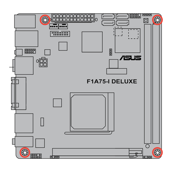
Place four screws into the holes indicated by circles to secure the motherboard to the chassis. DO NOT overtighten the screws! Doing so can damage the motherboard. Place this side towards the rear of the chassis. F1A75-I DELUXE Chapter 1: Product introduction... -
Page 19: Motherboard Layout
1-23 System panel connector (10-1 pin F_PANEL) 1-26 14. AMD FM1 socket Speaker connector (4-pin SPEAKER) 1-26 15. Digital audio connector (4-1 pin SPDIF_OUT) 1-25 MemOK! switch 1-29 16. Front panel audio connector (10-1 pin AAFP) 1-27 ASUS F1A75-I DELUXE... -
Page 20: Accelerated Processing Unit (Apu)
Installing the APU To install a APU: Locate the FM1 socket on the motherboard. F1A75-I DELUXE F1A75-I DELUXE CPU socket FM1 Socket lever Press the lever sideways to unlock the socket, then lift it up to a 90°-100° angle. Ensure that the socket lever is lifted up to a 90°-100° angle; otherwise, the APU will not fit in completely. - Page 21 Connect the CPU fan cable to the CPU_FAN connector on the motherboard. CPU_FAN F1A75-I DELUXE F1A75-I DELUXE CPU fan connector DO NOT forget to connect the CPU fan connector! Hardware monitoring errors can occur if you fail to plug this connector.
-
Page 22: Installing The Heatsink And Fan
1.6.2 Installing the heatsink and fan To install the CPU heatsink and fan: Place the heatsink on top of the installed CPU, ensuring that the heatsink fits properly on the retention module base. • The retention module base is already installed on the motherboard upon purchase. •... - Page 23 Push down the retention bracket lock on the retention mechanism to secure the heatsink and fan to the module base. ASUS F1A75-I DELUXE 1-11...
-
Page 24: System Memory
DDR2 DIMM socket. DDR3 modules are developed for better performance with less power consumption. The figure illustrates the location of the DDR3 DIMM sockets: Channel Sockets Channel A DIMM_A1 Channel B DIMM_B1 F1A75-I DELUXE F1A75-I DELUXE 240-pin DDR3 DIMM sockets 1-12 Chapter 1: Product introduction... -
Page 25: Memory Configurations
• The maximum 16GB memory capacity can be supported with 8GB or above DIMMs. ASUS will update the memory QVL once the DIMMs are available in the market. • The default memory operation frequency is dependent on its Serial Presence Detect (SPD), which is the standard way of accessing information from a memory module. - Page 26 DDR3-1333 MHz capability DIMM socket support Chip Vendors Part No. Size Chip NO. Timing Voltage (Optional) Brand AD30908C8D-151C A-Data AD31333001GOU A-Data • • E0906 A-Data AD63I1B0823EV A-Data 3CCA-1509A • • 1.25V- A-Data AXDU1333GC2G9-2G(XMP) 4GB(2 x 2GB) 9-9-9-24 1.35V(low • • voltage) A-Data AD31333G002GMU...
- Page 27 • • TAKEMS TMS1GB364D081-138EY 8-8-8-24 1.5V • • TAKEMS TMS2GB364D081-107EY 7-7-7-20 1.5V • TAKEMS TMS2GB364D081-138EY 8-8-8-24 1.5V • TAKEMS TMS2GB364D082-138EW 8-8-8-24 1.5V • • UMAX E41302GP0-73BDB UMAX U2S24D30TP-13 • • WINTEC 3WVS31333-2G-CNR AMPO AM3420803-13H • • ASUS F1A75-I DELUXE 1-15...
- Page 28 DDR3-1600 MHz capability DIMM socket Chip support (Optional) Vendors Part No. Size SS/DS Brand Chip NO. Timing Voltage A-Data AX3U1600XC4G79-2X(XMP) 8GB(2 x 4GB) 7-9-7-21 1.55V-1.75V • • CORSAIR TR3X3G1600C8D(XMP) 3GB(3 x 1GB) 8-8-8-24 1.65V • CORSAIR CMD12GX3M6A1600C8(XMP) 12GB(6 x 2GB) DS 8-8-8-24 1.65V •...
- Page 29 • A*: Supports one module inserted into any slot as single-channel memory configuration. • B*: Supports one pair of modules inserted into either the blue slots or the black slots as one pair of dual-channel memory configuration. Visit the ASUS website at www.asus.com for the latest QVL. ASUS F1A75-I DELUXE 1-17...
-
Page 30: Installing A Dimm
1.7.3 Installing a DIMM To remove a DIMM 1-18 Chapter 1: Product introduction... -
Page 31: Expansion Slots
BIOS setup. Assign an IRQ to the card. Install the software drivers for the expansion card. 1.8.3 PCI Express x16 slots This motherboard supports a PCI Express x16 graphics card that complys with the PCI Express specifications. ASUS F1A75-I DELUXE 1-19... -
Page 32: Jumpers
Clear RTC F1A75-I DELUXE (Default) F1A75-I DELUXE Clear RTC RAM To erase the RTC RAM: 1. Turn OFF the computer and unplug the power cord. 2. Move the jumper cap from pins 1-2 (default) to pins 2-3. Keep the cap on pins 2-3 for about 5~10 seconds, then move the cap back to pins 1-2. -
Page 33: Connectors
Bluetooth devices. • Under Windows 7 OS, to achieve the complete Bluetooth functions, download the latest ® Bluetooth driver from the ASUS support wedsite at http://support.asus.com. • Bluetooth Electrical Specification: Bluetooth specification V.2.1 compliant; Transmission rate up to 3 Mbps;... - Page 34 HDMI port. This port is for a High-Definition Multimedia Interface (HDMI) connector, and is HDCP compliant allowing playback of HD DVD, Blu-ray, and other protected content. Line In port (light blue). This port connects the tape, CD, DVD player, or other audio sources.
-
Page 35: Internal Connectors
• The CPU_FAN connector supports a CPU fan of maximum 2A (24 W) fan power. • Only the 4-pin CPU fan and chassis fan support the ASUS Fan Xpert feature. • If you install two VGA cards, we recommend that you plug the rear chassis fan cable to the motherboard connector labeled CHA_FAN1 for better thermal environment. - Page 36 The system may become unstable or may not boot up if the power is inadequate. • If you are uncertain about the minimum power supply requirement for your system, refer to the Recommended Power Supply Wattage Calculator at http://support.asus. com/PowerSupplyCalculator/PSCalculator.aspx?SLanguage=en-us for details. 1-24...
- Page 37 SATA6G_2 F1A75-I DELUXE F1A75-I DELUXE SATA 6.0Gb/s connectors • These connectors are set to IDE mode by default. In IDE mode, you can connect Serial ATA boot/data hard disk drives to these connectors. If you intend to create a Serial ATA RAID set using these connectors, set the type of the SATA connectors in the BIOS to [RAID].
-
Page 38: System Panel Connector
PIN 1 F1A75-I DELUXE +HDLED RESET F1A75-I DELUXE System panel connector • System power LED (2-pin PLED) This 2-pin connector is for the system power LED. Connect the chassis power LED cable to this connector. The system power LED lights up when you turn on the system power, and blinks when the system is in sleep mode. -
Page 39: Usb 3.0 Connector
This connector is for the additional USB 3.0 ports. Connect the USB 3.0 bracket cable to this connector, then install the USB 3.0 bracket to the rear side of the chassis. If your chassis support customized front panel installation, with ASUS USB 3.0 header, you can have a front panel USB 3.0 solution. - Page 40 This USB connector complies with USB 2.0 specification that supports up to 480Mbps connection speed. F1A75-I DELUXE USB56 F1A75-I DELUXE USB2.0 connector Never connect a 1394 cable to the USB connector. Doing so will damage the motherboard! The USB 2.0 module is purchased separately. 1-28...
-
Page 41: Onboard Switch
If the installed DIMMs still fail to boot after the whole tuning process, the DRAM_LED lights continuously. Replace the DIMMs with ones recommended in the Memory QVL (Qualified Vendors Lists) in this user manual or on the ASUS website at www.asus.com. -
Page 42: Onboard Leds
F1A75-I DELUXE Standby Power Powered Off F1A75-I DELUXE Onboard LED DRAM LED DRAM LED checks the DRAM in sequence during motherboard booting process. If an error is found , the LED next to the error device will continue lighting until the problem is solved. -
Page 43: Remote Controller
Use this key combined with another specific key to perform an action. Function 2 key Use this key combined with another specific key to enter the specific key’s characters. Caps Lock key Toggles the Caps Lock function on/off. ASUS F1A75-I DELUXE 1-31... -
Page 44: Function Keys
Minimize/Maximize key Minimizes/maximizes the computer screen. Direction Switch key Switches direction. Window switch key Mimics the standard keyboard’s <Alt>+<Tab> function, which allows you to switch between windows or screens. Navigation keys These keys mimic the mouse-click and scrolling functions of the standard keyboard and mouse. -
Page 45: Using The Remote Controller
LED flashes quickly, which indicates that the pairing process is completed. • The remote controller does not work under BIOS. • For details on using the remote controller’s keys, refer to the previous section Remote controller features. ASUS F1A75-I DELUXE 1-33... -
Page 46: Software Support
The contents of the Support DVD are subject to change at any time without notice. Visit the ASUS website at www.asus.com for updates. To run the Support DVD Place the Support DVD into the optical drive. -
Page 47: Chapter 2: Bios Information
BIOS in the future. Copy the original motherboard BIOS using the ASUS Update utility. 2.1.1 ASUS Update utility The ASUS Update is a utility that allows you to manage, save, and update the motherboard BIOS in Windows environment. ®... -
Page 48: Asus Ez Flash 2
Follow the onscreen instructions to complete the updating process. 2.1.2 ASUS EZ Flash 2 The ASUS EZ Flash 2 feature allows you to update the BIOS without using an OS-based utility. Before you start using this utility, download the latest BIOS file from the ASUS website at www.asus.com. -
Page 49: Asus Crashfree Bios 3 Utility
2.1.3 ASUS CrashFree BIOS 3 utility The ASUS CrashFree BIOS 3 is an auto recovery tool that allows you to restore the BIOS file when it fails or gets corrupted during the updating process. You can restore a corrupted BIOS file using the motherboard support DVD or a USB flash drive that contains the updated BIOS file. -
Page 50: Asus Bios Updater
2.1.4 ASUS BIOS Updater The ASUS BIOS Updater allows you to update BIOS in DOS environment. This utility also allows you to copy the current BIOS file that you can use as a backup when the BIOS fails or gets corrupted during the updating process. -
Page 51: Backing Up The Current Bios
The BIOS Updater backup screen appears indicating the BIOS backup process. When BIOS backup is done, press any key to return to the DOS prompt. ASUSTek BIOS Updater for DOS V1.07 Current ROM Update ROM BOARD: BOARD: Unknown F1A75-I DELUXE VER: VER: Unknown 0208 Unknown DATE: 06/20/2011... -
Page 52: Updating The Bios File
Select the Load Optimized Defaults item under the Exit menu. Refer to section 2.9 Exit menu for details. • Ensure to connect all SATA hard disk drives after updating the BIOS file if you have disconnected them. ASUS F1A75-I DELUXE... -
Page 53: Bios Setup Program
BIOS setup program Use the BIOS Setup program to update the BIOS or configure its parameters. The BIOS screens include navigation keys and brief online help to guide you in using the BIOS Setup program. Entering BIOS Setup at startup To enter BIOS Setup at startup: •... -
Page 54: Bios Menu Screen
Selects the boot device priority • The boot device options vary depending on the devices you installed to the system. • The Boot Menu(F8) button is available only when the boot device is installed to the system. ASUS F1A75-I DELUXE... -
Page 55: Advanced Mode
The Advanced Mode provides advanced options for experienced end-users to configure the BIOS settings. The figure below shows an example of the Advanced Mode. Refer to the following sections for the detailed configurations. To access the EZ Mode, click Exit, then select ASUS EZ Mode. Back button Menu items... -
Page 56: Menu Items
You cannot select an item that is not user-configurable. A configurable field is highlighted when selected. To change the value of a field, select it and press <Enter> or click on it to display a list of options. 2-10 ASUS F1A75-I DELUXE... -
Page 57: Main Menu
Main menu The Main menu screen appears when you enter the Advanced Mode of the BIOS Setup program. The Main menu provides you an overview of the basic system information, and allows you to set the system date, time, language, and security settings. EFI BIOS Utility - Advanced Mode Exit Main... -
Page 58: Administrator Password
To clear the user password, follow the same steps as in changing a user password, but press <Enter> when prompted to create/confirm the password. After you clear the password, the User Password item on top of the screen shows Not Installed. 2-12 ASUS F1A75-I DELUXE... -
Page 59: Ai Tweaker Menu
Ai Tweaker menu The Ai Tweaker menu items allow you to configure overclocking-related items. Be cautious when changing the settings of the Ai Tweaker menu items. Incorrect field values can cause the system to malfunction. The configuration options for this section vary depending on the CPU and DIMM model you installed on the motherboard. -
Page 60: Ai Overclock Tuner [Auto]
APU Multiplier [Auto] Allows you to set the multiplier between the CPU Core Clock and the FSB Frequency. Use the <+> and <-> keys to adjust the ratio. The valid value ranges vary according to your CPU model. 2-14 ASUS F1A75-I DELUXE... -
Page 61: Epu Power Saving Mode [Disabled]
2.4.4 EPU Power Saving Mode [Disabled] Allows you to enable or disable the EPU power saving function. Configuration options: [Disabled] [Enabled] EPU Setting [Auto] This item appears only when The EPU Power Saving Mode is set to [Enabled] and allows you to set power saving mode. Configuration options: [Auto] [Light Power Saving Mode] [Medium Power Saving Mode] [Max Power Saving Mode] 2.4.5 OC Tuner... -
Page 62: Sb 1.1V Voltage [Auto]
CPU Load Line affects CPU voltage. The CPU working voltage decreases proportionally to CPU loading. Adjust the voltage range to control CPU Load Line. Select a high value for system performance or a low value for power efficiency. Configuration options: [Auto] [Regular] [Medium] [High] [Extreme] 2-16 ASUS F1A75-I DELUXE... -
Page 63: Apu Spread Spectrum [Auto]
CPU/NB loading. Configuration options: [100%] [110%] [120%] [130%] CPU Power Phase Control [Standard] [Standard] Phase control based on CPU command. [Optimized] ASUS optimized phase tuning profile [Extreme] Full phase mode [Manual Adjustment] Phase number adjusted by current (A) step Do not remove the thermal module when switching to Extreme and Manual modes. -
Page 64: Advanced Menu
Disables this function. C6 Mode [Auto] Enables or disables C6 mode. Configuration options: [Auto] [Enabled] [Disabled] CPB Mode [Auto] Disables the CPB (Core Performance Boost) mode or set it to [Auto] for automatic configuration. Configuration options: [Disabled] [Auto] 2-18 ASUS F1A75-I DELUXE... -
Page 65: Sata Configuration
AMD PowerNow function [Enabled] Enables or disables the AMD PowerNow function. Configuration options: [Enabled] [Disabled] SVM [Enabled] Enables or disables CPU virtualization. Configuration options: [Disabled] [Enabled] C-state Pmin [Enabled] When this item is set to [Enabled], the system’s processor operates at the lowest power and operating state (C-state). -
Page 66: Usb Configuration
This item appears only when you set the previous item to [Force]. Configuration options: [Auto] [32M] [64M] [128M] [256M] [384M] [512M] [1G] [2G] DVI/Display Port Output [Auto] Sets the DVI/Display port output type. Configuration options: [Auto] [DVI [DisplayPort] 2-20 ASUS F1A75-I DELUXE... -
Page 67: Onboard Devices Configuration
2.5.5 Onboard Devices Configuration HD Audio Device [Enabled] [Enabled] Enables the High Definition Audio Controller. [Disabled] Disables the controller. The following two items appear only when you set the HD Audio Device item to [Enabled]. Front Panel Type [HD] Allows you to set the front panel audio connector (AAFP) mode to legacy AC’97 or high- definition audio depending on the audio standard that the front panel audio module supports. -
Page 68: Monitor Menu
+5.160 V F12: Print Screen Version 2.00.1201. Copyright (C) 2011 American Megatrends, Inc. Scroll down to display the following items: 12V Voltage +12.000 V Anti Surge Support Enabled Version 2.00.1201. Copyright (C) 2011 American Megatrends, Inc. 2-22 ASUS F1A75-I DELUXE... -
Page 69: Cpu Temperature / Mb Temperature [Xxxºc/Xxxºf]
2.6.1 CPU Temperature / MB Temperature [xxxºC/xxxºF] The onboard hardware monitor automatically detects and displays the CPU and motherboard temperatures. Select Ignore if you do not wish to display the detected temperatures. 2.6.2 CPU / Chassis Fan Speed [xxxx RPM] or [Ignore] / [N/A] The onboard hardware monitor automatically detects and displays the CPU / chassis fan speeds in rotations per minute (RPM). -
Page 70: Chassis Q-Fan Control [Enabled]
The onboard hardware monitor automatically detects the voltage output through the onboard voltage regulators. Select Ignore if you do not want to detect this item. 2.6.6 Anti Surge Support [Enabled] This item allows you to enable or disable the Anti Surge function. Configuration options: [Disabled] [Enabled] 2-24 ASUS F1A75-I DELUXE... -
Page 71: Boot Menu
[Disabled] Disables the full screen logo display feature. Set this item to [Enabled] to use the ASUS MyLogo 2™ feature. Post Report [5 sec] This item appears only when the Full Screen Logo item is set to [Disabled] and allows you to set the waiting time for the system to display the post report. -
Page 72: Option Rom Messages [Force Bios]
• To select the boot device during system startup, press <F8> when ASUS Logo appears. • To access Windows OS in Safe Mode, press <F8> after POST. -
Page 73: Tools Menu
> ASUS SPD Information 2.8.1 ASUS EZ Flash 2 Utility Allows you to run ASUS EZ Flash 2. Press [Enter] to launch the ASUS EZ Flash 2 screen. For more details, see section 2.1.2 ASUS EZ Flash 2. 2.8.2 ASUS O.C. Profile This item allows you to store or load multiple BIOS settings. -
Page 74: Exit Menu
This option allows you to enter the EZ Mode screen. Launch EFI Shell from filesystem device This option allows you to attempt to launch the UEFI Shell application (shellx64.efi) from one of the available devices that have a filesystem. 2-28 ASUS F1A75-I DELUXE... -
Page 75: Asus Contact Information
+1-510-739-3777 +1-510-608-4555 Web site usa.asus.com Technical Support Telephone +1-812-282-2787 Support fax +1-812-284-0883 Online support support.asus.com ASUS COMPUTER GmbH (Germany and Austria) Address Harkort Str. 21-23, D-40880 Ratingen, Germany +49-2102-959911 Web site www.asus.de Online contact www.asus.de/sales Technical Support Telephone (Component) +49-1805-010923*...
Need help?
Do you have a question about the F1A75-I DELUXE and is the answer not in the manual?
Questions and answers