Table of Contents
Advertisement
Advertisement
Table of Contents

Related Manuals for Gigabyte GA-78LMT-S2


Summary of Contents for Gigabyte GA-78LMT-S2
- Page 1 GA-78LMT-S2 User's Manual Rev. 1001...
-
Page 3: Identifying Motherboard Revision
The trademarks mentioned in this manual are legally registered to their respective owners. Disclaimer Information in this manual is protected by copyright laws and is the property of GIGABYTE. Changes to the specifications and features in this manual may be made by GIGABYTE without prior notice. -
Page 4: Table Of Contents
Table of Contents GA-78LMT-S2 Motherboard Layout ................5 GA-78LMT-S2 Motherboard Block Diagram ..............6 Chapter 1 Hardware Installation ..................7 Installation Precautions ..................7 1-2 Product Specifications ..................8 Installing the CPU ..................10 Installing the Memory ..................11 Installing an Expansion Card ................. 11 Back Panel Connectors .................. -
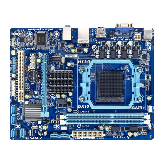
Page 5: Ga-78Lmt-S2 Motherboard Layout
GA-78LMT-S2 Motherboard Layout CPU_FAN KB_MS ATX_12V AM3+ R_USB USB_LAN GA-78LMT-S2 AUDIO AMD 760G GbE LAN M_BIOS PCIEX16 AMD SB710 Super I/O PCIEX1 CODEC F_USB1 SATA2 F_AUDIO F_USB2 F_USB1 F_PANEL CLR_CMOS SYS_FAN Box Contents GA-78LMT-S2 motherboard Motherboard driver disk Two SATA cables... -
Page 6: Ga-78Lmt-S2 Motherboard Block Diagram
GA-78LMT-S2 Motherboard Block Diagram CPU CLK+/- (200 MHz) 1 PCI Express x16 AM3+/AM3 CPU DDR3 1333+ (O.C.)/1066/800 MHz Dual Channel Memory PCIe CLK Hyper Transport 3.0 RJ45 (100 MHz) Atheros/Realtek GbE LAN GFX CLK (100 MHz) D-Sub AMD 760G PCI Express Bus... -
Page 7: Chapter 1 Hardware Installation
Chapter 1 Hardware Installation Installation Precautions The motherboard contains numerous delicate electronic circuits and components which can become damaged as a result of electrostatic discharge (ESD). Prior to installation, carefully read the user's manual and follow these procedures: • Prior to installation, make sure the chassis is suitable for the motherboard. •... -
Page 8: Product Specifications
4 Dual channel memory architecture Š Support for DDR3 1333+ (O.C.)/1066/800 MHz memory modules Š (Go to GIGABYTE's website for the latest supported memory speeds and memory modules.) Onboard North Bridge: Š... - Page 9 Internal 1 x 24-pin ATX main power connector Š Connectors 1 x 4-pin ATX 12V power connector Š 6 x SATA 3Gb/s connectors Š 1 x CPU fan header Š 1 x system fan headers Š 1 x front panel header Š...
-
Page 10: Installing The Cpu
Micro ATX Form Factor; 24.4cm x 18.8cm Form Factor Š * GIGABYTE reserves the right to make any changes to the product specifications and product-related information without prior notice. Installing the CPU Read the following guidelines before you begin to install the CPU: •... -
Page 11: Installing The Memory
• Make sure that the motherboard supports the memory. It is recommended that memory of the same capacity, brand, speed, and chips be used. (Go to GIGABYTE's website for the latest supported memory speeds and memory modules.) • Always turn off the computer and unplug the power cord from the power outlet before installing the memory to prevent hardware damage. -
Page 12: Back Panel Connectors
Back Panel Connectors PS/2 Keyboard and PS/2 Mouse Port Use the upper port (green) to connect a PS/2 mouse and the lower port (purple) to connect a PS/2 keyboard. D-Sub Port The D-Sub port supports a 15-pin D-Sub connector. Connect a monitor that supports D-Sub connection to this port. -
Page 13: Internal Connectors
Internal Connectors ATX_12V F_AUDIO F_USB1/F_USB2 CPU_FAN CLR_CMOS SYS_FAN SATA2 0/1/2/3/4/5 F_PANEL Read the following guidelines before connecting external devices: • First make sure your devices are compliant with the connectors you wish to connect. • Before installing the devices, be sure to turn off the devices and your computer. Unplug the power cord from the power outlet to prevent damage to the devices. - Page 14 1/2) ATX_12V/ATX (2x2 12V Power Connector and 2x12 Main Power Connector) With the use of the power connector, the power supply can supply enough stable power to all the components on the motherboard. Before connecting the power connector, first make sure the power supply is turned off and all devices are properly installed.
-
Page 15: Sata 3Gb/S Connectors
3/4) CPU_FAN/SYS_FAN (Fan Headers) The motherboard has a 4-pin CPU fan header (CPU_FAN) and a 3-pin system fan header (SYS_FAN). Most fan headers possess a foolproof insertion design. When connecting a fan cable, be sure to connect it in the correct orientation (the black connector wire is the ground wire). The speed control function requires the use of a fan with fan speed control design. -
Page 16: F_Panel (Front Panel Header)
6) F_PANEL (Front Panel Header) Connect the power switch, reset switch, speaker, chassis intrusion switch/sensor and system status indicator on the chassis to this header according to the pin assignments below. Note the positive and negative pins before connecting the cables. Message/Power/ Sleep LED Power Switch... -
Page 17: Front Panel Audio Header
7) F_AUDIO (Front Panel Audio Header) The front panel audio header supports Intel High Definition audio (HD) and AC'97 audio. You may connect your chassis front panel audio module to this header. Make sure the wire assignments of the module connector match the pin assignments of the motherboard header. -
Page 18: Battery
9) CLR_CMOS (Clear CMOS Jumper) Use this jumper to clear the CMOS values (e.g. date information and BIOS configurations) and reset the CMOS values to factory defaults. To clear the CMOS values, use a metal object like a screwdriver to touch the two pins for a few seconds. -
Page 19: Chapter 2 Bios Setup
To see more advanced BIOS Setup menu options, you can press <Ctrl> + <F1> in the main menu of the BIOS Setup program. To upgrade the BIOS, use either the GIGABYTE Q-Flash or @BIOS utility. Q-Flash allows the user to quickly and easily upgrade or back up BIOS without entering the operating •... -
Page 20: The Main Menu
The Main Menu Once you enter the BIOS Setup program, the Main Menu (as shown below) appears on the screen. Use arrow keys to move among the items and press <Enter> to accept or enter a sub-menu. (Sample BIOS Version: F1a) CMOS Setup Utility-Copyright (C) 1984-2012 Award Software Load Fail-Safe Defaults MB Intelligent Tweaker(M.I.T.) -
Page 21: Mb Intelligent Tweaker(M.i.t.)
MB Intelligent Tweaker(M.I.T.) CMOS Setup Utility-Copyright (C) 1984-2012 Award Software MB Intelligent Tweaker(M.I.T.) Item Help IGX Configuration [Press Enter] Menu Level CPU Clock Ratio [Auto] 2800Mhz CPU NorthBridge Freq. [Auto] 2000Mhz Core Performance Boost [Enabled] (Note) CPB Ratio [Auto] 3100Mhz (Note) Turbo CPB [Disabled]... - Page 22 Surround View Enables or disables the Surround View function. This option is configurable only when Init Display First under Advanced BIOS Features is set to PEG and an ATI graphics card is installed. (Default: Disabled) VGA Core Clock control Allows you to determine whether to manually set the VGA Core clock. (Default: Auto) VGA Core Clock(MHz) Allows you to manually set the VGA Core clock.
- Page 23 DRAM E.O.C.P Allows you to determine whether to use the preset memory overclocking profile to achieve optimum overclocking performance. (Default: Disabled) Set Memory Clock Determines whether to manually set the memory clock. Auto lets BIOS automatically set the memory clock as required. Manual allows the memory clock control item below to be configurable. (Default: Auto) Memory Clock This option is configurable only when Set Memory Clock is set to Manual.
- Page 24 TwTr Command Delay Options are: Auto (default), 4T~7T. Trfc0 for DIMM1 Options are: Auto (default), 90ns, 110ns, 160ns, 300ns, 350ns. Trfc1 for DIMM2 Options are: Auto (default), 90ns, 110ns, 160ns, 300ns, 350ns. Write Recovery Time Options are: Auto (default), 5T~8T, 10T, 12T. Precharge Time Options are: Auto (default), 4T~7T.
-
Page 25: Standard Cmos Features
Normal CPU Vcore Displays the normal operating voltage of your CPU. Normal CPU Vcore NB Displays the normal operating voltage of your CPU North Bridge. Standard CMOS Features CMOS Setup Utility-Copyright (C) 1984-2012 Award Software Standard CMOS Features Item Help Date (mm:dd:yy) Thu, Apr 19 2012... -
Page 26: Advanced Bios Features
Advanced BIOS Features CMOS Setup Utility-Copyright (C) 1984-2012 Award Software Advanced BIOS Features Item Help IGX Configuration [Press Enter] Menu Level Load Line Control [Auto] AMD C1E Support [Disabled] Virtualization [Disabled] AMD K8 Cool&Quiet control [Auto] CPU Unlock [Disabled] (Note) CPU core Control [Auto] (Note) - Page 27 (Default: Disabled) Full Screen LOGO Show Allows you to determine whether to display the GIGABYTE Logo at system startup. Disabled displays normal POST message. (Default: Enabled) (Note) This item is present only when you install a CPU that supports this feature.
-
Page 28: Integrated Peripherals
Init Display First Specifies the first initiation of the monitor display from the installed PCI graphics card, PCI Express graphics card, or the onboard graphics. PCI Slot Sets the PCI graphics card as the first display. (Default) OnChipVGA Sets the onboard graphics as the first display. Sets the PCI Express graphics card on the PCIEX16 slot as the first display. - Page 29 OnChip SATA Port as ESP CMOS Setup Utility-Copyright (C) 1984-2012 Award Software OnChip SATA Port as ESP Item Help Port0 as ESP [Disabled] Menu Level Port1 as ESP [Disabled] Port2 as ESP [Disabled] Port3 as ESP [Disabled] x Port4 as ESP Disabled x Port5 as ESP Disabled...
-
Page 30: Power Management Setup
USB Legacy Function Allows USB keyboard to be used in MS-DOS. (Default: Enabled) USB Storage Function Determines whether to detect USB storage devices, including USB flash drives and USB hard drives during the POST. (Default: Enabled) Onboard Serial Port Enables or disables the first serial port and specifies its base I/O address and corresponding interrupt. Options are: Auto, 3F8/IRQ4 (default), 2F8/IRQ3, 3E8/IRQ4, 2E8/IRQ3, Disabled. - Page 31 PME Event Wake Up Allows the system to be awakened from an ACPI sleep state by a wake-up signal from a PCI or PCIe device. Note: To use this function, you need an ATX power supply providing at least 1A on the +5VSB lead.
-
Page 32: Pnp/Pci Configurations
PnP/PCI Configurations CMOS Setup Utility-Copyright (C) 1984-2012 Award Software PnP/PCI Configurations Item Help PCI1 IRQ Assignment [Auto] Menu Level : Move Enter: Select +/-/PU/PD: Value F10: Save ESC: Exit F1: General Help F5: Previous Values F6: Fail-Safe Defaults F7: Optimized Defaults PCI1 IRQ Assignment Auto BIOS auto-assigns IRQ to the first PCI slot. -
Page 33: Load Fail-Safe Defaults
Current System/CPU Temperature Displays current system/CPU temperature. Current CPU/SYSTEM FAN Speed (RPM) Displays current CPU/system fan speed. CPU Warning Temperature Sets the warning threshold for CPU temperature. When CPU temperature exceeds the threshold, BIOS will emit warning sound. Options are: Disabled (default), 60 C/140 F, 70 C/158... -
Page 34: Load Optimized Defaults
2-11 Load Optimized Defaults CMOS Setup Utility-Copyright (C) 1984-2012 Award Software MB Intelligent Tweaker(M.I.T.) Load Fail-Safe Defaults Load Optimized Defaults Standard CMOS Features Advanced BIOS Features Set Supervisor Password Integrated Peripherals Set User Password Power Management Setup Save &... -
Page 35: Save & Exit Setup
2-13 Save & Exit Setup CMOS Setup Utility-Copyright (C) 1984-2012 Award Software MB Intelligent Tweaker(M.I.T.) Load Fail-Safe Defaults Load Optimized Defaults Standard CMOS Features Advanced BIOS Features Set Supervisor Password Save to CMOS and EXIT (Y/N)? Y Integrated Peripherals Set User Password ... -
Page 36: Chapter 3 Drivers Installation
Chapter 3 Drivers Installation • Before installing the drivers, first install the operating system. • After installing the operating system, insert the motherboard driver disk into your optical drive. The driver Autorun screen is automatically displayed which looks like that shown in the screen shot below. - Page 37 Steps: 1. Turn on your computer and press <Delete> to enter BIOS Setup during the POST (Power-On Self-Test). Ensure OnChip SATA Controller is enabled under Integrated Peripherals. To enable RAID for the SATA2 0/1/2/3 connectors, set OnChip SATA Type to RAID. To enable RAID for the SATA2 4/SATA2 5 connectors, set OnChip SATA Type to RAID and set OnChip SATA Port4/5 Type to As SATA Type.
- Page 38 Making a SATA RAID/AHCI Driver Diskette Before installing Windows XP, connect a USB floppy disk drive to your computer first because you need to install the SATA RAID/AHCI driver from a floppy disk that contains the driver during the OS installation. To copy the RAID/AHCI driver for Windows XP, copy all files in the \BootDrv\SBxxx folder in the motherboard driver disk to your floppy disk.
-
Page 39: Regulatory Statements
"end of life" product. Restriction of Hazardous Substances (RoHS) Directive Statement GIGABYTE products have not intended to add and safe from hazardous substances (Cd, Pb, Hg, Cr+6, PBDE and PBB). The parts and components have been carefully selected to meet RoHS requirement. Moreover, we at GIGABYTE are continuing our efforts to develop products that do not use internationally banned toxic chemicals. - Page 40 - 40 -...
- Page 41 - 41 -...
- Page 42 - 42 -...
- Page 43 - 43 -...
- Page 44 Tech. and Non-Tech. Support (Sales/Marketing) : http://ggts.gigabyte.com.tw WEB address (English): http://www.gigabyte.com WEB address (Chinese): http://www.gigabyte.tw You may go to the GIGABYTE website, select your language in the language list on the top right corner of the website. • GIGABYTE Global Service System To submit a technical or non-technical (Sales/Marketing) question, please link to: http://ggts.gigabyte.com.tw...
Need help?
Do you have a question about the GA-78LMT-S2 and is the answer not in the manual?
Questions and answers