Table of Contents
Advertisement
Advertisement
Table of Contents

Related Manuals for Asus Motherboard A8N-SLI SE


Summary of Contents for Asus Motherboard A8N-SLI SE
- Page 1 A8N-SLI SE...
- Page 2 Product warranty or service will not be extended if: (1) the product is repaired, modified or altered, unless such repair, modification of alteration is authorized in writing by ASUS; or (2) the serial number of the product is defaced or missing.
-
Page 3: Table Of Contents
Welcome! ... 1-1 Package contents ... 1-1 Special features ... 1-2 1.3.1 Product highlights ... 1-2 1.3.2 ASUS Proactive features ... 1-4 1.3.3 Innovative ASUS features ... 1-5 Chapter 2: Hardware information Before you proceed ... 2-1 Motherboard overview ... 2-2 2.2.1... - Page 4 4.1.2 Updating the BIOS ... 4-2 4.1.3 Saving the current BIOS file ... 4-4 4.1.4 ASUS CrashFree BIOS 2 utility ... 4-5 4.1.5 ASUS EZ Flash utility ... 4-7 4.1.6 ASUS Update utility ... 4-8 BIOS setup program ... 4-11 4.2.1...
- Page 5 Contents 4.3.1 System Time ... 4-15 4.3.2 System Date ... 4-15 4.3.3 Legacy Diskette A ... 4-15 4.3.4 Primary and Secondary IDE Master/Slave ... 4-16 4.3.5 First, Second, Third, Fourth SATA Master ... 4-18 4.3.6 HDD SMART Monitoring ... 4-19 4.3.7 Installed Memory ...
- Page 6 Voltage/Fan control ... 5-33 5.7.4 Information ... 5-34 5.7.5 Other options ... 5-34 Using the ASUS AI Selector utility ... 5-35 5.8.1 Launching the ASUS AI Selector ... 5-35 5.8.2 Using the SLI mode ... 5-36 Chapter 6: SLI™ technology support Overview ...
- Page 7 6.2.2 Installing the device drivers ... 6-5 6.2.3 Installing the ASUS AI Selector utility ... 6-5 6.2.4 Enabling the multi-GPU feature in Windows ... 6-6 6.2.5 Setting the ASUS AI Selector utility ... 6-8...
-
Page 8: Canadian Department Of Communications Statement
Notices Federal Communications Commission Statement This device complies with Part 15 of the FCC Rules. Operation is subject to the following two conditions: • This device may not cause harmful interference, and • This device must accept any interference received including interference that may cause undesired operation. -
Page 9: Electrical Safety
Safety information Electrical safety • To prevent electrical shock hazard, disconnect the power cable from the electrical outlet before relocating the system. • When adding or removing devices to or from the system, ensure that the power cables for the devices are unplugged before the signal cables are connected. -
Page 10: About This Guide
About this guide This user guide contains the information you need when installing and configuring the motherboard. How this guide is organized This manual contains the following parts: • Chapter 1: Product introduction This chapter describes the features of the motherboard and the new technology it supports. -
Page 11: Where To Find More Information
Refer to the following sources for additional information and for product and software updates. ASUS websites The ASUS website provides updated information on ASUS hardware and software products. Refer to the ASUS contact information. Optional documentation Your product package may include optional documentation, such as warranty flyers, that may have been added by your dealer. -
Page 12: Specifications
- RAID 0, RAID 1, RAID 0+1, and JBOD that spans across the Serial ATA and Parallel ATA drives AI NOS™ (Non-Delay Overclocking System) ASUS AI Overclocking (Intelligent CPU frequency tuner) ASUS PEG Link for single/dual graphics card Fixed PCI Express/PCI/SATA frequencies ASUS C.P.R. - Page 13 1 x Serial port connector (COM port) 1 x 24-pin ATX power connector 1 x 4-pin ATX 12 V power connector 1 x 4-pin ASUS EZ Plug™ connector 3 x USB 2.0 connectors for 6 additional USB 2.0 ports 1 x Internal audio connectors (CD\AUX)
- Page 14 ATX power supply (with 24-pin and 4-pin 12 V plugs) ATX 12 V 2.0 compliant ATX form factor: 12 in x 9.6 in (30.5 cm x 24.4 cm) Device drivers ASUS PC Probe II ASUS Live Update utility ASUS CoolʼnʼQuiet! utility Anti-virus utility (OEM version) NVIDIA nTune™...
-
Page 15: Chapter 1: Product Introduction
This chapter describes the motherboard features and the new technologies it supports. Product introduction... -
Page 16: Chapter Summary
Chapter summary Welcome! ... 1-1 Package contents ... 1-1 Special features ... 1-2 ASUS A8N-SLI SE... -
Page 17: Welcome
T h a n k y o u f o r b u y i n g a n A S U S The motherboard delivers a host of new features and latest technologies, making it another standout in the long line of ASUS quality motherboards! Before you start installing the motherboard, and hardware devices on it, check the items in your package with the list below. -
Page 18: Special Features
Special features 1.3.1 Product highlights Latest processor technology The AMD Athlon™ 64FX, Athlon™ 64 and Athlon 64x2 desktop processors are based on AMDʼs 64-bit and 32-bit architecture, which represents the landmark introduction of the industryʼs first x86-64 technology. These processors provide a dramatic leap forward in compatibility, performance, investment protection, and reduced total cost of ownership and development. -
Page 19: Hypertransport™ Technology
The motherboard supports the S/PDIF Out function through the S/PDIF interfaces on the rear panel. The S/PDIF technology turns your computer into a high-end entertainment system with digital connectivity to powerful audio and speaker systems. See page 2-18 for details. ASUS A8N-SLI SE... -
Page 20: Asus Proactive Features
See section “4.5.4 Hardware Monitor” on page 4-37. 1.3.2 ASUS Proactive features AI NOS™ (Non-Delay Overclocking System) ASUS Non-delay Overclocking System™ (NOS) is a technology that auto-detects the CPU loading and dynamically overclocks the CPU speed only when needed. See page 4-30 for details. AI Audio technology The motherboard supports 6-channel audio through the onboard ALC850 CODEC with 16-bit DAC, a stereo 16-bit ADC, and an AC97 2.3 compatible... -
Page 21: Innovative Asus Features
See page 5-35 for details. ASUS EZ Plug™ This patented ASUS technology is a 4-pin auxiliary +12V connector that is designed to maintain the voltage integrity of your system. This plug guarantees adequate supply of power to the motherboard and other installed peripherals. - Page 22 Chapter 1: Product introduction...
-
Page 23: Chapter 2: Hardware Information
This chapter lists the hardware setup procedures that you have to perform when installing system components. It includes description of the jumpers and connectors on the motherboard. Hardware information... - Page 24 Chapter summary Before you proceed ... 2-1 Motherboard overview ... 2-2 Central Processing Unit (CPU) ... 2-6 System memory ... 2-11 Expansion slots ... 2-14 Jumpers ... 2-17 Connectors ... 2-18 ASUS A8N-SLI SE...
-
Page 25: Onboard Led
The illustration below shows the location of the onboard LED. The red warning LED lights up when you installed two graphics card but did not connect the ASUS EZ Plug™. The illustration below shows the location of the onboard LEDs. A8N-SLI SE ®... -
Page 26: Motherboard Overview
Motherboard overview Before you install the motherboard, study the configuration of your chassis to ensure that the motherboard fits into it. Make sure to unplug the power cord before installing or removing the motherboard. Failure to do so can cause you physical injury and damage motherboard components. -
Page 27: Motherboard Layout
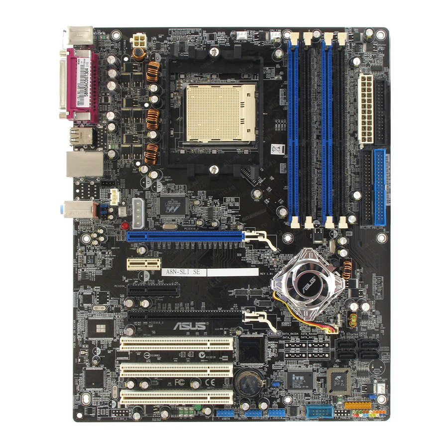
Gigabit PHY Top:Line In Center:Line Out Bottom:Mic In EZ_PLUG PCIEX16_1 ALC850 PCIEX1_1 A8N-SLI SE PCIEX4_1 PCIEX16_2 PCI1 PCI2 PCI3 ASUS A8N-SLI SE 24.5cm (9.6in) CPU_FAN CHA2_FAN NVIDIA nForce4 SLI Super CR2032 3V Lithium Cell CMOS Power CLRTC USB78 USB56 USB910... -
Page 28: Layout Contents
2.2.4 Layout Contents Slots 1. DDR DIMM slots 2. PCI slots 3. PCI Express x16 slot 4. PCI Express x1 slot 5. PCI Express x4 slot Jumpers 1. Clear RTC RAM (3-pin CLRTC1) Rear panel connectors 1. PS/2 mouse port (green) 2. - Page 29 - System Power LED (Green 3-pin PLED) - Hard Disk activity (Red 2-pin IDE_LED) - System warning speaker (Orange 4-pin SPEAKER) - Power/Soft-off button(Yellow 2-pin PWRSW) - Reset switch (Blue 2-pin RESET) ASUS A8N-SLI SE Page 2-21 2-21 2-22 2-23...
-
Page 30: Central Processing Unit (Cpu)
Central Processing Unit (CPU) 2.3.1 Overview The motherboard comes with a surface mount 939-pin Zero Insertion Force (ZIF) socket designed for the AMD Athlon™ 64FX, AMD Athlon™ 64 or AMD Athlon™ 64X2 processor. The 128-bit-wide data paths of these processors can run applications faster than processors with only 32-bit or 64-bit wide data paths. - Page 31 CPU! When the CPU is in place, push down the socket lever to secure the CPU. The lever clicks on the side tab to indicate that it is locked. ASUS A8N-SLI SE Socket Lever Small triangle Gold triangle...
-
Page 32: Installing The Heatsink And Fan
2.3.3 Installing the heatsink and fan The AMD Athlon™ 64FX, AMD Athlon™ 64X2 or AMD Athlon 64™ processor require a specially designed heatsink and fan assembly to ensure optimum thermal condition and performance. Make sure that you use only qualified heatsink and fan assembly. Follow these steps to install the CPU heatsink and fan. - Page 33 fits the retention mechanism module base, otherwise you cannot snap the retention bracket in place. Push down the retention bracket lock on the retention mechanism to secure the heatsink and fan to the module base. ASUS A8N-SLI SE...
- Page 34 When the fan and heatsink assembly is in place, connect the CPU fan cable to the connector on the motherboard labeled CPU_FAN. A8N-SLI SE ® A8N-SLI SE CPU Fan Connector Do not forget to connect the CPU fan connector! Hardware monitoring errors can occur if you fail to plug this connector.
-
Page 35: System Memory
4 GB of system memory when you installed four 1 GB DDR memory modules. • Due to CPU limitation, DIMM modules with 128 Mb memory chips or double-sided x16 memory chips are not supported in this motherboard. ASUS A8N-SLI SE Sockets DIMM_A1 and DIMM_A2 DIMM_B1 and DIMM_B2 2-11... - Page 36 DDR400 Qualified Vendors List Size Vendor Model 1024MB KINGSTON KVR400X64C3A/1G 1024MB CORSAIR TWINX2048-3200C2 1024MB Transcend TS128MLD64V4J 256MB KINGSTON KVR400X64C3A/256 512MB KINGSTON KVR400X64C3A/512 256MB KINGSTON KVR400X72C3A/256 512MB KINGSTON KVR400X72C3A/512 256MB KINGSTON KVR400X64C3A/256 512MB KINGSTON KVR400X64C3A/512 256MB KINGSTON KVR400X64C3A/256 512MB KINGSTON KVR400X64C3A/512 512MB KINGSTON KHX3200A/512...
- Page 37 Dual-channel memory configuration. C - support for 4 modules inserted into the blue and black slots as two pairs of Dual-channel memory configuration. Visit the ASUS website (www.asus.com) for the latest DDR 400 Qualified Vendors List. ASUS A8N-SLI SE...
-
Page 38: Installing A Dimm
2.4.3 Installing a DIMM Make sure to unplug the power supply before adding or removing DIMMs or other system components. Failure to do so may cause severe damage to both the motherboard and the components. Unlock a DIMM socket by pressing the retaining clips outward. -
Page 39: Expansion Slots
Turn on the system and change the necessary BIOS settings, if any. See Chapter 4 for information on BIOS setup. Assign an IRQ to the card. Refer to the tables on the next page. Install the software drivers for the expansion card. ASUS A8N-SLI SE 2-15... -
Page 40: Standard Interrupt Assignments
2.5.3 Interrupt assignments Standard interrupt assignments Priority – * These IRQs are usually available for ISA or PCI devices. IRQ assignments for this motherboard PCI slot 1 PCI slot 2 PCI slot 3 Onboard USB 1.0 controller Onboard USB 2.0 controller When using PCI cards on shared slots, ensure that the drivers support “Share IRQ”... -
Page 41: Two Pci Express X16 Slots
PCI Express x4 slot This motherboard provides a PCI Express x4 slot that can support PCI Express x1 and x4 cards. This ASUS proprietary slot allows you to use additional PCI Express cards for twice the speed of a PCI Express x1 slot. -
Page 42: Jumpers
Jumpers Clear RTC RAM (CLRTC) This jumper allows you to clear the Real Time Clock (RTC) RAM in CMOS. You can clear the CMOS memory of date, time, and system setup parameters by erasing the CMOS RTC RAM data. The onboard button cell battery powers the RAM data in CMOS, which include system setup information such as system passwords. -
Page 43: Connectors
USB 2.0 ports 1 and 2. These two 4-pin Universal Serial Bus (USB) ports are available for connecting USB 2.0 devices. Coaxial S/PDIF Out port. This port connects an external audio output device via a coaxial S/PDIF cable. ASUS A8N-SLI SE SPEED LED Status Description... - Page 44 10. PS/2 keyboard port (purple). This port is for a PS/2 keyboard. Refer to the audio configuration table below for the function of the audio ports in 2, 4, or 6-channel configuration. Audio 2, 4, or 6-channel configuration Port Light Blue Lime Pink 2-20...
-
Page 45: Internal Connectors
• Use the 80-conductor IDE cable for UltraDMA133/100/66 IDE devices. A8N-SLI SE ® A8N-SLI SE IDE Connectors ASUS A8N-SLI SE FLOPPY NOTE: Orient the red markings o n the floppy ribbon cable to PIN 1. PIN 1 NOTE: Orient the red marking s (usually zigzag) on the IDE ribbon cable to PIN 1. -
Page 46: Serial Ata Connectors
Serial ATA connectors (7-pin SATA1, SATA2, SATA3, SATA4) Supported by the NVIDIA the Serial ATA signal cables for Serial ATA hard disk drives that allows up to 3Gb/s of data transfer rate. If you installed Serial ATA hard disk drives, you can create a RAID 0, RAID 1, RAID 0+1, or JBOD configuration that span across the Parallel ATA drives. - Page 47 These are not jumpers! DO NOT place jumper caps on the fan connectors! • The ASUS Q-Fan2 function is supported using the CPU Fan (CPU_ FAN) and Chassis Fan 1 (CHA1_FAN) connectors only. • The chipset fan is synchronized with the CPU fan.
-
Page 48: Serial Port Connector (10-1 Pin Com1)
Serial port connector (10-1 pin COM1) This connector is for a serial (COM) port. Connect the serial port module cable to this connector, then install the module to a slot opening at the back of the system chassis. A8N-SLI SE ®... -
Page 49: Power Supply Requirements
PCIe™ x 1 card PCI cards USB devices Required +12V current Required wattage A8N-SLI SE ® A8N-SLI SE ATX Power Connectors ASUS A8N-SLI SE Heavy Athlon 64 FX-55 Athlon 64 3800+ 6800 Ultra x2 6800GT x2 > 25A >= 500W >= 400W... -
Page 50: Game/Midi Port Connector (16-1 Pin Game)
Internal audio connectors (4-pin CD, AUX) These connectors allow you to receive stereo audio input from sound sources such as a CD-ROM, TV-tuner, or MPEG card. A8N-SLI SE ® A8N-SLI SE Internal Audio Connectors GAME/MIDI port connector (16-1 pin GAME) This connector is for a GAME/MIDI port. -
Page 51: Chassis Intrusion/Front Panel Audio Connector
AC ʻ97 audio standard. Connect one end of the front panel audio I/O module cable to this connector. A8N-SLI SE ® A8N-SLI SE Front Panel Audio Connector ASUS A8N-SLI SE CHASSIS (Default ) FP_AUDIO BLINE_OUT_L Line out_L... -
Page 52: System Panel Connector
12. System panel connector (20-pin PANEL) This connector supports several chassis-mounted functions. A8N-SLI SE ® A8N-SLI SE System Panel Connector The sytem panel connector is color-coded for easy connection. Refer to the connector description below for details. • System power LED (Green 3-pin PLED) This 3-pin connector is for the system power LED. -
Page 53: Chapter 3: Powering Up
This chapter describes the power up sequence and the ways of shutting down the system. Powering up... -
Page 54: Chapter Summary
Chapter summary Starting up for the first time ... 3-1 Powering off the computer ... 3-2 ASUS A8N-SLI SE... -
Page 55: Starting Up For The First Time
Check the jumper settings and connections or call your retailer for assistance. At power on, hold down the <Delete> key to enter the BIOS Setup. Follow the instructions in Chapter 4. ASUS A8N-SLI SE... -
Page 56: Powering Off The Computer
Powering off the computer 3.2.1 Using the OS shut down function If you are using Windows Click the Start button then click Shut Down... Make sure that the Shut Down option button is selected, then click the OK button to shut down the computer. The power supply should turn off after Windows If you are using Windows Click the Start button then select Turn Off Computer. -
Page 57: Chapter 4: Bios Setup
This chapter tells how to change the system settings through the BIOS Setup menus. Detailed descriptions of the BIOS parameters are also provided. BIOS setup... - Page 58 Chapter summary Managing and updating your BIOS ... 4-1 BIOS setup program ... 4-11 Main menu ... 4-15 Advanced menu ... 4-20 Power menu ... 4-34 Boot menu ... 4-39 Exit menu ... 4-45 ASUS A8N SLI SE...
-
Page 59: Managing And Updating Your Bios
ASUS CrashFree BIOS 2 (Updates the BIOS using a bootable floppy disk or the motherboard support CD when the BIOS file fails or gets corrupted.) ASUS EZ Flash (Updates the BIOS in DOS using a floppy disk or the motherboard support CD.) ASUS Update (Updates the BIOS in Windows Refer to the corresponding sections for details on these utilities. -
Page 60: Updating The Bios
AwardBIOS Flash Utility. Follow these instructions to update the BIOS using this utility. 1. Download the latest BIOS file from the ASUS web site. Rename the file to A8NSLI-B.BIN and save it to a floppy disk. Save only the updated BIOS file in the floppy disk to avoid loading the wrong BIOS file. - Page 61 flashed the BIOS file. Remove the floppy disk then press <F1> to restart the system. ASUS A8N-SLI SE AwardBIOS Flash Utility for ASUS V1.01 (C) Phoenix Technologies Ltd. All Rights Reserved For NF-KC804-A8N-SLI-00 Flash Type - SST 49LF004A/B /3.3V File Name to Program: 1001.bin...
-
Page 62: Saving The Current Bios File
4. The utility saves the current BIOS file to the floppy disk, then returns to the BIOS flashing process. AwardBIOS Flash Utility for ASUS V1.01 (C) Phoenix Technologies Ltd. All Rights Reserved For NF-KC804-A8N-SLI-00 Flash Type - SST 49LF004A/B /3.3V File Name to Program: 1001.bin... -
Page 63: Asus Crashfree Bios 2 Utility
4.1.4 ASUS CrashFree BIOS 2 utility The ASUS CrashFree BIOS 2 is an auto recovery tool that allows you to restore the BIOS file when it fails or gets corrupted during the updating process. You can update a corrupted BIOS file using the motherboard support CD or the floppy disk that contains the updated BIOS file. -
Page 64: Recovering The Bios From A Floppy Disk
Restart the system after the utility completes the updating process. The recovered BIOS may not be the latest BIOS version for this motherboard. Visit the ASUS website (www.asus.com) to download the latest BIOS file. Chapter 4: BIOS setup... -
Page 65: Asus Ez Flash Utility
4.1.5 ASUS EZ Flash utility The ASUS EZ Flash feature allows you to update the BIOS without having to go through the long process of booting from a floppy disk and using a DOS-based utility. The EZ Flash utility is built-in the BIOS chip so it is accessible by pressing <Alt>... -
Page 66: Asus Update Utility
4.1.6 ASUS Update utility The ASUS Update is a utility that allows you to manage, save, and update the motherboard BIOS in Windows allows you to: • Save the current BIOS file • Download the latest BIOS file from the Internet •... -
Page 67: Updating The Bios Through The Internet
Updating the BIOS through the Internet To update the BIOS through the Internet: Launch the ASUS Update utility from the Windows Start > Programs > ASUS > ASUSUpdate > ASUSUpdate. The ASUS Update main window appears. Select Update BIOS from... -
Page 68: Updating The Bios Through A Bios File
Updating the BIOS through a BIOS file To update the BIOS through a BIOS file: Launch the ASUS Update utility from the Windows by clicking Start > Programs > ASUS > ASUSUpdate > ASUSUpdate. The ASUS Update main window appears. Select Update BIOS from a file option from the drop-down menu, then click Next. -
Page 69: Bios Setup Program
The BIOS setup screens shown in this section are for reference purposes only, and may not exactly match what you see on your screen. • Visit the ASUS website (www.asus.com) to download the latest BIOS file for this motherboard. ASUS A8N-SLI SE 4-11... -
Page 70: Bios Menu Screen
The BIOS setup screens shown in this chapter are for reference purposes only, and may not exactly match what you see on your screen. • Visit the ASUS website (www.asus.com) to download the latest BIOS information. 4-12 Configuration fields Phoenix-Award BIOS CMOS Setup Utility... -
Page 71: Legend Bar
A configurable field is enclosed in brackets, and is highlighted when selected. To change the value of a field, select it then press <Enter> to display a list of options. Refer to “4.2.7 Pop-up window.” ASUS A8N-SLI SE Function Displays the General Help screen... -
Page 72: Pop-Up Window
Main Advanced Power System Time System Date Legacy Diskette A: Primary IDE Master Primary IDE Slave [ASUS CDS520/A] Secondary IDE Master Secondary IDE Slave First SATA Master [None] Second SATA Slave [None] Third SATA Master [None] Fourth SATA Slave [None]... -
Page 73: Main Menu
Phoenix-Award BIOS CMOS Setup Utility Main Advanced Power System Time System Date Legacy Diskette A: Primary IDE Master Primary IDE Slave [ASUS CDS520/A] Secondary IDE Master Secondary IDE Slave First SATA Master Second SATA Slave Third SATA Master Fourth SATA Slave HDD SMART Monitoring... -
Page 74: Primary And Secondary Ide Master/Slave
4.3.4 Primary and Secondary IDE Master/Slave While entering Setup, the BIOS automatically detects the presence of IDE devices. There is a separate sub-menu for each IDE device. Select a device item then press <Enter> to display the IDE device information. Main Primary IDE Master Primary IDE Master... -
Page 75: Transfer Mode
FDISK, to partition and format new IDE hard disk drives. This is necessary so that you can write or read data from the hard disk. Make sure to set the partition of the Primary IDE hard disk drives to active. ASUS A8N-SLI SE 4-17... -
Page 76: First, Second, Third, Fourth Sata Master
4.3.5 First, Second, Third, Fourth SATA Master While entering Setup, the BIOS automatically detects the presence of Serial ATA devices. There is a separate sub-menu for each SATA device. Select a device item then press <Enter> to display the SATA device information. Main Primary IDE Master Extended IDE Drive... -
Page 77: Hdd Smart Monitoring
Allows you to enable or disable the HDD Self-Monitoring Analysis and Reporting Technology (SMART) feature. Configuration options: [Disabled] [Enabled] 4.3.7 Installed Memory Shows the size of installed memory. 4.3.8 Usable Memory Shows the size of usable memory. ASUS A8N-SLI SE 4-19... -
Page 78: Advanced Menu
Advanced menu The Advanced menu items allow you to change the settings for the CPU and other system devices. Take caution when changing the settings of the Advanced menu items. Incorrect field values can cause the system to malfunction. Main Advanced Power CPU Configuration... -
Page 79: Dram Configuration
Shows the minimum RAS# active time. This item is not configurable. RAS# to CAS# delay (Trcd) Shows the RAS# to CAS# delay to Rd/Wr command on the same bank. This item is not configurable. ASUS A8N-SLI SE [Auto] Item Specific Help 400Mhz <Enter>... - Page 80 Row precharge Time (Trp) Shows the Row precharge time. This item is not configurable. Row Cycle Time (Trc) Shows the row cycle time. This item is not configurable. Row Refresh Cycle Time (Trfc) Shows the row refresh cycle time. This item is not configurable. Read-to-Write time (Trwt) Shows the read-to-write time.This item is not configurable.
-
Page 81: Pci Pnp
When the item Resources Controlled By is set to [Auto], the item IRQ Resources is grayed out and not user-configurable. Refer to the section “IRQ Resources” for information on how to enable this item. ASUS A8N-SLI SE [No] Item Specific Help... -
Page 82: Onboard Devices Configuration
IRQ Resources This sub-menu is activated only when the Resources Controlled By item is set to Manual. Advanced IRQ-3 assigned to IRQ-4 assigned to [PCI Device] IRQ-5 assigned to [PCI Device] IRQ-7 assigned to [PCI Device] IRQ-9 assigned to [PCI Device] IRQ-10 assigned to IRQ-11 assigned to IRQ-12 assigned to... -
Page 83: Ide Function Setup
Allows you to enable or disable the SATA DMA transfer access. Configuration options: [Disabled] [Enabled] Serial Port 3, 4 [Enabled] Allows you to enable or disable the SATA 3 and 4 ports. Configuration options: [Disabled] [Enabled] ASUS A8N-SLI SE [Enabled] Item Specific Help [Enabled] Disable/Enable OnChip IDE [Enabled] Channel 10. - Page 84 SATA2 DMA transfer [Enabled] Allows you to enable or disable the SATA2 DMA transfer access. Configuration options: [Disabled] [Enabled] IDE Prefetch Mode [Enabled] Allows you to enable or disable the IDE prefetch mode. Configuration options: [Disabled] [Enabled] NVRAID Configuration This sub-menu contains NVRAID function-related items. Select an item then press <Enter>...
-
Page 85: Usb Configuration
Allows you to enable or disable the onboard LAN boot ROM. Configuration options: [Disabled] [Enabled] AC97 Audio [Enabled] Allows you to disable or enabled the onboard AC97 audio controller. Configuration options: [Disabled] [Enabled] ASUS A8N-SLI SE [Enabled] Item Specific Help [Enabled] [Enabled] Enable/Disable USB2.0 and... -
Page 86: Serial Port1 Address [3F8/Irq4]
Serial Port1 Address [3F8/IRQ4] Allows you to select the Serial Port1 base address. Configuration options: [Disabled] [3F8/IRQ4] [3E8/IRQ4] [2E8/IRQ3] Parallel Port Address [378/IRQ7] Allows you to select the Parallel Port base addresses. Configuration options: [Disabled] [378/IRQ7] [278/IRQ5] [3BC/IRQ7] Parallel Port Mode [ECP+EPP] Allows you to select the Parallel Port mode. -
Page 87: Sli Configuration
We recommend to keep the setting of this item to [Auto]. • When not set to [Auto], make sure that the setting is the same as the ASUS AI Selector. If the BIOS setting is not the same as the AI Selector utility, the system follows the latter. •... -
Page 88: Jumperfree Configuration
Loads the optimal settings for the system. Loads the standard settings for the system. Loads overclocking profiles with optimal parameters for stability when overclocking. The ASUS AI Non-delay Overclocking System feature intelligently determines the system load and automatically boost the performance for the most demanding tasks. - Page 89 [1.100V] [1.0875V] [1.075V] [1.0625V] [1.050V] [1.0375V] [1.025V] [1.0125V] [1.000V] [0.9875V] [0.975V] [0.9625V] [0.950V] [0.9375V] [0.925V] [0.9125V] [0.900V] [0.8875V] [0.875V] [0.8625V] [0.850V] [0.8375V] [0.825V] [0.8125V] [0.800V] PCI Clock Synchronization Mode [Auto] Sets the PCI Clock Synchronization mode. Configuration options: [Auto] [To CPU] [33.33MHz] ASUS A8N-SLI SE 4-31...
-
Page 90: Peg Link Mode
The following item is user-configurable only when the AI Overclocking item is set to [AI Overclock]. Overclock Options [Disabled] Allows you to set the oveclocking options. Configuration options: [Disable] [Overclock 3%] [Overclock 5%] [Overclock 8%] [Overclock 10%] The following item is user-configurable only when the AI Overclocking item is set to [AI N.O.S.]. - Page 91 Allows you to enable or disable the PCI Express graphics root control. Configuration options: [Auto] [Enabled] [Disabled] PEG Buffer Length [Auto] Allows you to set the PCI Express graphics buffer length. For optimum performance, set this item to Auto. Configuration options: [Auto] [Long] [Short] [Medium] ASUS A8N-SLI SE 4-33...
-
Page 92: Power Menu
Power menu The Power menu items allow you to change the settings for the Advanced Configuration and Power Interface (ACPI) and the Advanced Power Management (APM). Select an item then press <Enter> to display the configuration options. Main Advanced Power ACPI Suspend Type ACPI APIC support APM Configuration... -
Page 93: Apm Configuration
Thus, connection cannot be made on the first try. Turning an external modem off and then back on while the computer is off causes an initialization string that turns the system power on. ASUS A8N SLI SE [Disabled] Item Specific Help [Instant Off]... - Page 94 Power On By RTC Alarm [Disabled] Allows you to enable or disable RTC to generate a wake event. When this item is set to Enabled, the items Date of Month Alarm and Time (hh:mm:ss) Alarm items become user-configurable with set values. Configuration options: [Disabled] [Enabled] Day of Month Alarm [Disabled] To set the date of alarm, highlight this item and press <Enter>...
-
Page 95: Hardware Monitor
The onboard hardware monitor automatically detects and displays the Chassis, CPU, and Chip fan speeds in rotations per minute (RPM). If the fan is not connected to the motherboard, the field shows 0. These items are not user-configurable. ASUS A8N SLI SE [Disabled] Item Specific Help 1.50V] 3.31V]... - Page 96 CPU Target Temperature Allows you to set the temperature threshold before the CPU fan stops. Configuration options: [51ºC] [54ºC] [57ºC] [60ºC] [63ºC] [66ºC] [69ºC] [72ºC] [75ºC] [78ºC] [81ºC] CPU Fan Speed warning [1200 RPM] Allows you to set the CPU fan warning speed. Configuration options: [Disabled] [800 RPM] [1200 RPM] [1600 RPM] CHA1 Fan Speed warning [Disabled] Allows you to set the chassis fan warning speed.
-
Page 97: Boot Menu
The number of device items that appears on the screen depends on the number of devices installed in the system. Configuration options: [Removable] [Hard Disk] [CDROM] [Legacy LAN] [Disabled] ASUS A8N SLI SE Boot Exit -/+: Change Value Enter: Select Sub-menu... -
Page 98: Removable Drives
4.6.2 Removable Drives 1. Floppy Disks F1:Help ↑↓ : Select Item ESC: Exit →←: Select Menu 1. Floppy Disks Allows you to assign a removable drive attached to the system. 4.6.3 Hard Disk Drives 1. Bootable Add-in Cards F1:Help ↑↓ : Select Item ESC: Exit →←: Select Menu 1. -
Page 99: Boot Settings Configuration
Typematic Rate (Chars/Sec) and the Typematic Delay (Msec). Configuration options: [Disabled] [Enabled] The items Typematic Rate (Chars/Sec) and Typematic Delay (Msec) becomes user-configurable only when the item Typematic Rate Setting is enabled. ASUS A8N SLI SE Boot [Enabled] [Enabled] [Disabled]... -
Page 100: Typematic Rate (Chars/Sec)
Make sure that the above item is set to [Enabled] if you want to use the ASUS MyLogo2™ feature. • See section “5.4.1 ASUS MyLogo2™” for details. Halt On [All, But Keyboard] Allows you to error report type. Configuration options: [All Errors] [No Errors] [All, But Keyboard]... -
Page 101: Security
Select the password field and press <Enter> twice. The following message appears: PASSWORD DISABLED !!! Press any key to continue... Press any key to continue. The password field setting is changed to Clear. ASUS A8N SLI SE Boot Clear Clear [Setup] -/+: Change Value... - Page 102 A note about passwords The Supervisor password is required to enter the BIOS Setup program preventing unauthorized access. The User password is required to boot the system preventing unauthorized use. Forgot your password? If you forget your password, you can clear it by erasing the CMOS Real Time Clock (RTC) RAM.
-
Page 103: Exit Menu
Select this option only if you do not want to save the changes that you made to the Setup program. If you made changes to fields other than System Date, System Time, and Password, the BIOS asks for a confirmation before exiting. ASUS A8N SLI SE Boot Exit -/+: Change Value... -
Page 104: Load Setup Defaults
Load Setup Defaults This option allows you to load the default values for each of the parameters on the Setup menus. When you select this option or if you press <F5>, a confirmation window appears. Select Yes to load default values. -
Page 105: Chapter 5: Software Support
This chapter describes the contents of the support CD that comes with the motherboard package. Software support... - Page 106 Software information ... 5-9 RAID configurations ... 5-20 Creating a RAID driver disk ... 5-29 Cool ʻnʼ Quiet!™ Technology ... 5-30 Using the NVIDIA ® Using the ASUS AI Selector utility ... 5-35 ASUS A8N-SLI SE nTune™ utility ... 5-32...
-
Page 107: Installing An Operating System
The contents of the support CD are subject to change at any time without notice. Visit the ASUS website(www.asus.com) for updates. 5.2.1 Running the support CD Place the support CD to the optical drive. -
Page 108: Drivers Menu
5.2.2 Drivers menu The drivers menu shows the available device drivers if the system detects installed devices. Install the necessary drivers to activate the devices. Nvidia Chipset Driver Program Installs the NVIDIA ® Make NVIDIA PATA RAID Driver Disk Creates the NVIDIA Make NVIDIA SATA RAID Driver Disk Creates the NVIDIA Realtek ALC850 Driver... -
Page 109: Utilities Menu
The ASUS AI Booster application allows you to overclock the CPU speed in a Windows environment. ® ASUS AI Selector The ASUS AI Selector utility allows you to set the video card mode of your system. Refer to 5.8 Using the ASUS AI Selector Utility for details. ASUS A8N-SLI SE... -
Page 110: Adobe Acrobat Reader
ADOBE Acrobat Reader Installs the Adobe Acrobat Reader V7.0 that allows you to open, view, ® ® and print documents in Portable Document Format (PDF). ASUS Screen Saver Installs the ASUS Screen Saver. Chapter 5: Software support... -
Page 111: Manuals Menu
Allows you to open the NVIDIA NVIDIA nTune Manual Allows you to open the NVIDIA NVRAID Disk Alert Userʼs Guide Allows you to open the NVIDIA ASUS A8N-SLI SE Acrobat Reader from the Utilities menu before ® ® ForceWare Networking and Firewall ®... -
Page 112: Asus Contact Information
5.2.5 ASUS Contact information Click the Contact tab to display the ASUS contact information. You can also find this information on the inside front cover of this user guide. 5.2.6 Other information The icons on the top right corner of the screen give additional information on the motherboard and the contents of the support CD. -
Page 113: Technical Support Form
Browse this CD Displays the support CD contents in graphical format. Technical support Form Displays the ASUS Technical Support Request Form that you have to fill out when requesting technical support. ASUS A8N-SLI SE... - Page 114 Filelist Displays the contents of the support CD and a brief description of each in text format. Chapter 5: Software support...
-
Page 115: Software Information
file that came with the software application for more information. 5.3.1 ASUS MyLogo2™ The ASUS MyLogo2™ utility lets you customize the boot logo. The boot logo is the image that appears on screen during the Power-On Self-Tests (POST). The ASUS MyLogo2™ is automatically installed when you install the ASUS Update utility from the support CD. - Page 116 Ratio box. When the screen returns to the ASUS Update utility, flash the original BIOS to load the new boot logo. 10. After flashing the BIOS, restart the computer to display the new boot logo during POST.
-
Page 117: Sound Effect Options
ALC850 Audio CODEC allows you to set your listening ® environment, adjust the equalizer, set the karaoke, or select pre-programmed equalizer settings for your listening pleasure. ASUS A8N-SLI SE Realtek SoundEffect icon technology features are supported on the ® ®... - Page 118 To set the sound effect options: From the Realtek Audio Control Panel, click the Sound Effect button. Click the shortcut buttons to change the acoustic environment, adjust the equalizer, or set the karaoke to your desired settings. The audio settings take effect immediately after you click on the buttons.
-
Page 119: Speaker Configuration
Auto Test to test your settings. Click the UAJ Automatic button to enable or disable the Universal Audio Jack(UAJ ) technology feature. ® Click the Exit (X) button on the upper-right hand corner of the window to exit. ASUS A8N-SLI SE 5-13... -
Page 120: Ai Audio Feature
AI Audio feature The AI Audio feature works through the connector sensing option that allows you to check if your audio devices are connected properly. To start the connector sensing: From the Realtek Audio Control Panel, click the Connector Sensing button. -
Page 121: Hrtf Demo
Click the option buttons to change the sound, moving path or EAX settings. Click the Play button to start or the Stop button to stop. Click the Exit (X) button on the upper-right hand corner of the window to exit. ASUS A8N-SLI SE 5-15... -
Page 122: Audio Configurations
General settings This option shows the audio settings and allows you to change the language setting or toggle the SoundEffect icon display on the Windows taskbar. To display the general settings: From the Realtek Audio Control Panel, click the General button. Click the option button to enable or disable the icon display on the Windows taskbar. -
Page 123: Using The Nvidia ® Firewall
Double-click the icon to display the NVFirewall™ Summary menu. Click to select firewall profile Click to view profile details Click to view the firewall log Click to view the firewall stats ASUS A8N-SLI SE Firewall™ ® Firewall™ (NVFirewall™) application ® NVIDIA Firewall™ icon ®... - Page 124 Setting security profiles The NVFirewall™ application allows several security profiles to match your system security needs. The following describes the NVFirewall™ security profiles: • Low - allows safe incoming connections and deny those that are known to be dangerous connections. This profile also enables some anti-hacking features.
- Page 125 firewall. To turn off the NVFirewall™: From the NVIDIA Firewall™ summary menu, click the Current Firewall Profile combo list box then select Off. The following confirmation box appears. Click Turn Firewall OFF. ASUS A8N-SLI SE 5-19...
-
Page 126: Raid Configurations
RAID configurations The motherboard comes with the NVIDIA that allow you to configure IDE and Serial ATA hard disk drives as RAID sets. The motherboard supports the following RAID configurations. RAID 0 (Data striping) optimizes two identical hard disk drives to read and write data in parallel, interleaved stacks. -
Page 127: Installing Hard Disks
Connect the SATA signal cables. Connect a SATA power cable to the power connector on each drive. Refer to the RAID controllers user manual in the motherboard support CD for detailed information on RAID configurations. See section “5.2.4 Manuals menu”. ASUS A8N-SLI SE 5-21... -
Page 128: Nvidia ® Raid Configurations
5.4.2 NVIDIA The motherboard includes a high performance IDE RAID controller integrated in the NVIDIA 1, RAID 0+1, and JBOD with four independent Serial ATA channels. Setting the BIOS RAID items After installing the hard disk drives, make sure to set the necessary RAID items in the BIOS before setting your RAID configuration. -
Page 129: Creating A Raid Volume
® Mode then press <Enter>. The following submenu appears. Use the up or down arrow keys to select a RAID mode then press <Enter>. ASUS A8N-SLI SE RAID utility ® NVIDIA RAID Utility Oct 5 2004 - Define a New Array -... - Page 130 Press <TAB> select the Striping Block then press <Enter>. The following submenu appears: If you selected Striping or Stripe Mirroring, use the up or down arrow keys to select the stripe size for your RAID 0 array then press <Enter>.The available values range from 8 KB to 128 KB. The default selection is 128 KB.
-
Page 131: Rebuilding A Raid Array
From the Array List menu, use the up or down arrow keys to select a RAID array then press <Enter>. The RAID Array details appear. RAID Mode: Mirroring Striping Width: 1 Adapt Channel [R] Rebuild ASUS A8N-SLI SE NVIDIA RAID Utility Oct 5 2004 - Array List - Status Vendor Array Model Name... - Page 132 A new set of navigation keys is displayed on the bottom of the screen. Press <R> to rebuild a RAID array. The following screen appears. RAID Mode: Mirroring Striping Width: 1 Adapt Channel Use the up or down arrow keys to select a RAID array to rebuild, then press <F7>.
-
Page 133: Deleting A Raid Array
Press <Y> to delete array or press <N> to cancel. Take caution in using this option. All data on the RAID drives will be lost! If you selected Yes, the Define a New Array menu appears. ASUS A8N-SLI SE Array 1 : NVIDIA MIRROR XXX.XXG... -
Page 134: Clearing A Disk Data
Clearing a disk data To clear disk data: From the Array List menu, use the up or down arrow keys to select a RAID array then press <Enter>. The RAID Array details appear. RAID Mode: Mirroring Striping Width: 1 Adapt Channel [R] Rebuild A new set of navigation keys is displayed on the bottom of the... -
Page 135: Creating A Raid Driver Disk
Follow the succeeding screen instructions to complete the installation. Due to chipset limitation, the Serial ATA ports supported by the NVIDIA chipset doesnʼt support Serial Optical Disk Drives (Serial ODD) under DOS. ASUS A8N-SLI SE ® RAID ® 5-29... -
Page 136: Cool ʻNʼ Quiet!™ Technology
Cool ‘n’ Quiet!™ Technology The motherboard supports the AMD Cool ʻnʼ Quiet!™ Technology that dynamically and automatically change the CPU speed, voltage, and amount of power depending on the task the CPU performs. 5.6.1 Enabling Cool ʻnʼ Quiet!™ Technology To enable Cool ʻnʼ Quiet!™ Technology: Turn on the system and enter BIOS by pressing the <Del>... -
Page 137: Launching The Cool ʻNʼ Quiet!™ Software
To launch the Cool ʻnʼ Quiet!™ program: If you are using Windows Select Programs > ASUS > Cool & Quiet > Cool & Quiet. If you are using Windows Programs > ASUS > Cool & Quiet > Cool & Quiet. -
Page 138: Using The Nvidia ® Ntune™ Utility
Using the NVIDIA The motherboard supports the NVIDIA and safe system tuning for optimum performance. This utility provides the safest and easiest way to tweak voltages or change system bus speeds and memory timings for maximum system performance. Follow the NVIDIA Chipset Driver Program installation wizard to install the NVIDIA nTune™... -
Page 139: Clock Control
Clock control menu 5.7.3 Voltage/Fan control The Voltage/Fan control menu allows tweaking options for the CPU and memory voltage. This menu also allows dynamic modifications for the CPU and auxiliary fan speeds. Click to launch the Voltage/Fan menu ASUS A8N-SLI SE 5-33... -
Page 140: Information
5.7.4 Information The information page displays related information about the processor, memory, motherboard, nForce™ profile, version information, and the calculated system performance results. Click to launch the Information page 5.7.5 Other options Other option buttons allow you to easily save or revert your settings and save or load nTune™... -
Page 141: Using The Asus Ai Selector Utility
Using the ASUS AI Selector utility The motherboard support CD comes with the ASUS AI Selector that allows you to set the video card mode of your system. Follow the AI Selector installation wizard to install the AI Selector utility from the motherboard support CD. -
Page 142: Using The Sli Mode
The utility prompts you to restart your system after setting the video card mode. Click Yes to implement settings and restart your system or No to return to the AI Selector menu. 5.8.2 Using the SLI mode To use SLI mode: Set the SLI Multi-GPU feature in Display Properties. -
Page 143: Nvidia Sli
This chapter tells how to install SLI-ready PCI Express graphics cards. NVIDIA SLI™ ® technology support... - Page 144 Chapter summary Overview ... 6-1 Dual graphics cards setup ... 6-3 ASUS A8N-SLI SE...
-
Page 145: Overview
The NVIDIA SLI technology supports Windows system only. • Visit the NVIDIA website for the supported 3D applications. • Visit the NVIDIA zone website (http://www.nzone.com) for the latest certified graphics card list. ASUS A8N-SLI SE SLI™ (Scalable Link Interface) ® XP™ operating ®... -
Page 146: Installing Sli-Ready Graphics Cards
6.2.1 Installing SLI-ready graphics cards Goldfingers Chapter 6: NVIDIA SLI™ technology support ®... - Page 147 Insert the second graphics card into the black slot labeled PCIEX16_2. Make sure that the card is properly seated on the slot. If required, connect an auxiliary power source to the PCI Express graphics cards. ASUS A8N-SLI SE...
- Page 148 If using a 20-pin ATX power connector, connect a 4-pin ATX power cable to the EZ Plug™ labeled EZ_PLUG on your motherboard. ASUS EZ Plug™ The onboard red warning LED lights up if you do not plug a 4-pin ATX power cable to the EZ Plug.
-
Page 149: Installing The Device Drivers
Install the ASUS AI Selector utility using the motherboard support CD. Follow the steps described in section “5.2.3 Utilities menu” and “5.8 Using the ASUS AI Selector Utilities” for how to use the ASUS AI Selector utility. ASUS A8N-SLI SE... -
Page 150: Enabling The Multi-Gpu Feature In Windows
6.2.4 Enabling the multi-GPU feature in Windows After installing your graphics cards and the device drivers, enable the Multi-Graphics Processing Unit (GPU) feature in the NVIDIA nView properties. To enable the multi-GPU feature: Click the NVIDIA Settings icon on your Windows taskbar. From the pop-up menu, select nView Desktop Manager then click nView Properties. - Page 151 From the Display Properties dialog box, select the Settings tab then click Advanced. Select the NVIDIA GeForce tab. Click the slider to display the following screen, then select the SLI multi-GPU item. ASUS A8N-SLI SE Slider...
-
Page 152: Setting The Asus Ai Selector Utility
When the SLI mode is disabled, the multi-monitor mode is automatically enabled. Use the NVIDIA nView utility to configure your multi-monitor setup. • See section “5.8 Using the ASUS AI Selector utility” on page 5-35 for details. PCIEX16_1 (blue) slot PCIEX16_2 (black) slot Card Type Speed Qualified PCIe x16...
Need help?
Do you have a question about the Motherboard A8N-SLI SE and is the answer not in the manual?
Questions and answers