Table of Contents
Advertisement
Quick Links
K8T80-A7
FCC Information and Copyright
This equipment has been tested and found to comply with the limits of a Class
B digital device, pursuant to Part 15 of the FCC Rules. These limits are designed
to provide reasonable protection against harmful interference in a residential
installation. This equipment generates, uses and can radiate radio frequency
energy and, if not installed and used in accordance with the instructions, may
cause harmful interference to radio communications. There is no guarantee
that interference will not occur in a particular installation.
The vendor makes no representations or warranties with respect to the
contents here and specially disclaims any implied warranties of merchantability
or fitness for any purpose. Further the vendor reserves the right to revise this
publication and to make changes to the contents here without obligation to
notify any party beforehand.
Duplication of this publication, in part or in whole, is not allowed without first
obtaining the vendor's approval in writing.
The content of this user's manual is subject to be changed without notice and
we will not be responsible for any mistakes found in this user's manual. All the
brand and product names are trademarks of their respective companies.
i
Advertisement
Table of Contents

Related Manuals for Biostar K8T80-A7


Summary of Contents for Biostar K8T80-A7
- Page 1 K8T80-A7 FCC Information and Copyright This equipment has been tested and found to comply with the limits of a Class B digital device, pursuant to Part 15 of the FCC Rules. These limits are designed to provide reasonable protection against harmful interference in a residential installation.
-
Page 2: Table Of Contents
Table of Contents Chapter 1: Introduction ............1 Features ....................1 Package List ..................3 Layout....................4 Components..................5 Chapter 2: Hardware Installation ..........6 Central Processing Unit (CPU)............6 FAN Headers..................8 Memory Module Installation ............8 Connectors and Slots ................9 Chapter 3: Headers & Jumpers Setup........10 How to Setup Jumpers ..............10 Detail Settings..................10 Chapter 4: Useful Help............14 Award BIOS Beep Code..............14... -
Page 3: Chapter 1: Introduction
K8T80-A7 CHAPTER 1: INTRODUCTION EATURES Supports Socket 754. Supports AMD Athlon 64/Sempron processor. Supports 200/400/600/800 clock rates with Double Data Rate style operation for 400/800/1200/1600MT/s in both directions simultaneously for Hyper Transport link. Chipset North Bridge: VIA K8T800. South Bridge: VIA VT8237R. - Page 4 K8T80-A7 Slot 5 x PCI bus master slots. 1 x AGP 4x/8x compatible slot. 1 x CNR slot. Serial ATA Integrated in SB VT8237R. Supports RAID 0 and RAID 1 functions. Supports 2 serial ATA (SATA) ports. Data transfer rates up to 150 MB/s.
-
Page 5: Package List
K8T80-A7 Back Panel I/O Connectors 4 USB 2.0 ports. 1 serial port. 1 parallel port. 1 RJ-45 LAN jack. 1 PS/2 Mouse & Keyboard port. 1 vertical audio port including 1 line-in connector, 1 Line out connector, and 1 MIC in connector. -
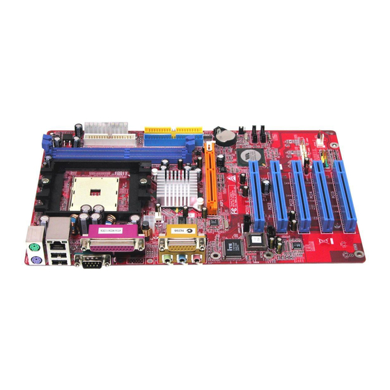
Page 6: Layout
K8T80-A7 AYOUT JCFAN1 JATXPWR2 JKBV1 JKBMS1 JATXPWR1 CPU1 JUSBV1 JUSB1 K8T800 Pro JUSBLAN1 JAUDIO1 AGP1 PCI1 JUSB4 JUSB3 JSATA2 VT8237R JUSBV2 PCI2 JSATA1 JCMOS1 JCI1 PCI3 JAUDIO2 Super I/O JCDIN1 PCI4 JSFAN1 JSPDIF_OUT1 BAT1 PCI5 Codec BIOS CNR1 JPANEL1 Note: ■ represents the 1... -
Page 7: Components
K8T80-A7 OMPONENTS Codec K8T800 Pro Super I/O BIOS VT8237R JATXPWR1/JATXPWR2: ATX power JSFAN1: System fan power source source headers. header. JKBV1: Power source header for JCMOS1: Clear CMOS header. JKBMS1. Rear side connectors (back panel). JCI1: Chassis open header. JUSBV1: Power source header for JSATA1/JSATA2: Serial ATA device USB ports at back panel. -
Page 8: Chapter 2: Hardware Installation
K8T80-A7 CHAPTER 2: HARDWARE INSTALLATION (CPU) ENTRAL ROCESSING Step 1: Pull the lever sideways away from the socket and then raise the lever up to a 90-degree angle. Step 2: Look for the black cut edge on socket, and the white dot on CPU should point forwards this black cut edge. - Page 9 K8T80-A7 Step 3: Hold the CPU down firmly, and then close the lever to complete the installation. Step 4: Put the CPU Fan on the CPU and buckle it. Connect the CPU FAN power cable to the JCFAN1. This completes the...
-
Page 10: Fan Headers
K8T80-A7 FAN H EADERS These fan headers support cooling-fans built in the computer. The fan wiring and plug may be different according to the fan manufacturer. Connect the fan cable to the connector while matching the black wire to pin#1. -
Page 11: Connectors And Slots
K8T80-A7 ONNECTORS AND LOTS The motherboard provides a standard floppy disk connector that supports 360K, 720K, 1.2M, 1.44M and 2.88M floppy disk types. This connector supports the provided floppy drive ribbon cables. The motherboard has a 32-bit Enhanced PCI IDE Controller that provides PIO Mode 0~5, Bus Master, and Ultra DMA 33/ 66/ 100 functionality. -
Page 12: Chapter 3: Headers & Jumpers Setup
K8T80-A7 CHAPTER 3: HEADERS & JUMPERS SETUP OW TO ETUP UMPERS The illustration shows how to set up jumpers. When the jumper cap is placed on pins, the jumper is “close”, if not, that means the jumper is “open”. Pin opened... - Page 13 K8T80-A7 JKBV1/JUSBV1/JUSBV2: Power Source Headers for USB ports Assignment Description JKBV1: +5V for JKBMS1. JUSBV1: +5V for JUSB1 and JUSBLAN1. Pin 1-2 close JUSBV2: +5V for JUSB3/JUSB4. JKBV1: JKBMS is powered with +5V standby voltage. +5V Standby JUSBV1: JUSB1 and JUSBLAN1 are Voltage powered with +5V standby voltage.
- Page 14 K8T80-A7 JSPDIF_OUT1: Digital Audio-out Connector This connector allows user to connect the PCI bracket SPDIF output header. Assignment SPDIF_OUT Ground JPANEL1: Front Panel Header This 24-pin connector includes Power-on, Reset, HDD LED, Power LED, Sleep button, speaker and IrDA Connection. It allows user to connect the PC case’s front panel switch functions.
- Page 15 K8T80-A7 JCMOS1: Clear CMOS Header By placing the jumper on pin2-3, it allows user to restore the BIOS safe setting and the CMOS data, please carefully follow the procedures to avoid damaging the motherboard. JCMOS1 Assignment Normal Operation (Default). Pin 1-2 close Clear CMOS data.
-
Page 16: Chapter 4: Useful Help
BIOS contents are corrupted. In this Case, please follow the procedure below to restore the BIOS: 1. Make a bootable floppy disk. 2. Download the Flash Utility “AWDFLASH.exe” from the Biostar website: www.biostar.com.tw 3. Confirm motherboard model and download the respectively BIOS from Biostar website. - Page 17 K8T80-A7 If the system shutdown automatically after power on system for seconds, that means the CPU protection function has been activated. When the CPU is over heated, the motherboard will shutdown automatically to avoid a damage of the CPU, and the system may not power on again.
-
Page 18: Troubleshooting
K8T80-A7 ROUBLESHOOTING Probable Solution No power to the system at all Make sure power cable is Power light don’t illuminate, fan securely plugged in. inside power supply does not turn Replace cable. Contact technical support. Indicator light on keyboard does not turn on. -
Page 19: Chapter 5: Warpspeeder
K8T80-A7 WARPSPEEDER™ CHAPTER 5: NTRODUCTION [WarpSpeeder™], a new powerful control utility, features three user-friendly functions including Overclock Manager, Overvoltage Manager, and Hardware Monitor. With the Overclock Manager, users can easily adjust the frequency they prefer or they can get the best CPU performance with just one click. The Overvoltage Manager, on the other hand, helps to power up CPU core voltage and Memory voltage. -
Page 20: Installation
K8T80-A7 NSTALLATION 1. Execute the setup execution file, and then the following dialog will pop up. Please click “Next” button and follow the default procedure to install. 2. When you see the following dialog in setup procedure, it means setup is completed. -
Page 21: Warpspeeder™] Includes 1 Tray Icon And 5 Panels
K8T80-A7 ™] PEEDER INCLUDES TRAY ICON AND PANELS Whenever the Tray Icon utility is launched, it will display a little tray icon on the right side of Windows Taskbar. This utility is responsible for conveniently invoking [WarpSpeeder™] Utility. You can use the mouse by clicking the left button in order to invoke [WarpSpeeder™] directly from the little tray icon or you can... - Page 22 K8T80-A7 If you click the tray icon, [WarpSpeeder™] utility will be invoked. Please refer to the following figure; the utility’s first window you will see is Main Panel. Main Panel contains features as follows: a. Display the CPU Speed, CPU external clock, Memory clock, AGP clock, and PCI clock information.
- Page 23 K8T80-A7 Click the Voltage button in Main Panel, the button will be highlighted and the Voltage Panel will slide out to up as the following figure. In this panel, you can decide to increase CPU core voltage and Memory voltage or not. The default setting is “No”. If you want to get the best performance of overclocking, we recommend you click the option “Yes”.
- Page 24 K8T80-A7 Click the Overclock button in Main Panel, the button will be highlighted and the Overclock Panel will slide out to left as the following figure. Overclock Panel contains the these features: a. “–3MHz button”, “-1MHz button”, “+1MHz button”, and “+3MHz button”: provide user the ability to do real-time overclock adjustment.
- Page 25 K8T80-A7 “Auto-overclock button”: User can click this button and [WarpSpeeder™] will set the best and stable performance and frequency automatically. [WarpSpeeder™] utility will execute a series of testing until system fail. Then system will do fail-safe reboot by using Watchdog function. After reboot, the [WarpSpeeder™] utility will restore to the hardware default...
- Page 26 K8T80-A7 Click the “about” button in Main Panel, the button will be highlighted and the About Panel will slide out to up as the following figure. In this panel, you can get model name and detail information in hints of all the chipset that are related to overclocking. You can also get the mainboard’s BIOS model and the Version number of...
- Page 27 K8T80-A7 Note: Because the overclock, overvoltage, and hardware monitor features are controlled by several separate chipset, [WarpSpeeder™] divide these features to separate panels. If one chipset is not on board, the correlative button in Main panel will be disabled, but will not interfere other panels’...
Need help?
Do you have a question about the K8T80-A7 and is the answer not in the manual?
Questions and answers