Asus A7V8X-MX SE User Manual
A7v8x-mx se user's manual
Hide thumbs
Also See for A7V8X-MX SE:
- Troubleshooting manual (64 pages) ,
- User manual (64 pages) ,
- Update manual (1 page)
Table of Contents
Advertisement
Quick Links
Advertisement
Table of Contents

Related Manuals for Asus A7V8X-MX SE


Summary of Contents for Asus A7V8X-MX SE
- Page 1 A7V8X-MX SE User Guide...
- Page 2 Product warranty or service will not be extended if: (1) the product is repaired, modified or altered, unless such repair, modification of alteration is authorized in writing by ASUS; or (2) the serial number of the product is defaced or missing.
-
Page 3: Table Of Contents
Notices ......................v Safety information ..................vi A7V8X-MX SE specification summary* ............. vii About this guide ..................viii Chapter 1: Product introduction Welcome! ..................1-2 Package contents ................1-2 Special features ................1-2 Motherboard components .............. 1-4 Motherboard layout ................ 1-7 Motherboard installation .............. - Page 4 Exit menu ..................2-27 Chapter 3: Software support Installing an operating system ............3-2 Support CD information ..............3-2 3.2.1 Running the support CD ..........3-2 3.2.2 Drivers menu ..............3-3 3.2.3 Utilities menu ..............3-4 3.2.4 ASUS contact information ..........3-5...
-
Page 5: Federal Communications Commission Statement
Federal Communications Commission Statement This device complies with FCC Rules Part 15. Operation is subject to the following two conditions: • This device may not cause harmful interference, and • This device must accept any interference received including interference that may cause undesired operation. -
Page 6: Electrical Safety
Electrical safety • To prevent electrical shock hazard, disconnect the power cable from the electrical outlet before relocating the system. • When adding or removing devices to or from the system, ensure that the power cables for the devices are unplugged before the signal cables are connected. If possible, disconnect all power cables from the existing system before you add a device. - Page 7 Socket A for AMD Athlon™XP up to 3200+ processor Thoroughbred/Barton core support Chipset VIA KM400 VIA VT8235 CE Front Side Bus (FSB) 333/266/200 MHz Memory 2 x 184-pin DDR DIMM sockets support up to maximum 2 GB unbuffered PC2700/2100/1600 non-ECC DDR SDRAM memory.
-
Page 8: Conventions Used In This Guide
Adobe Acrobat Reader ™ Trend Micro PC-cillin 2002 Accessories User Guide ASUS A7V8X-MX SE support CD UltraATA cable FDD cable I/O shield Form Factor Micro-ATX form factor: 9.6 in x 9.6 in * Specifications are subject to change without notice. -
Page 9: Product Introduction
This chapter describes the features of the motherboard. It includes brief descriptions of the motherboard components, and illustrations of the layout, jumper settings, and connectors. Product introduction... -
Page 10: Integrated Graphics
Check your ASUS A7V8X-MX SE package for the following items. ASUS A7V8X-MX SE motherboard.(Micro-ATX form factor: 9.6 in x 9.6 in) ASUS A7V8X-MX SE support CD 40-pin 80-conductor ribbon cable for UltraATA133 IDE drives Ribbon cable for a 3.5-inch floppy drive... -
Page 11: Asus Crashfree Bios
Integrated 10/100 LAN The A7V8X-MX SE motherboard comes with an onboard 10/100Mbps Fast Ethernet controller to give you a fast and reliable connection to a local area networks (LANs) and the Internet. USB 2.0 technology The motherboard implements the Universal Serial Bus (USB) 2.0 specification, dramatically increasing the connection speed from the 12 Mbps bandwidth on USB 1.1 to a fast 480 Mbps on USB 2.0. - Page 12 Before you install the motherboard, learn about its major components and available features to facilitate the installation and future upgrades. Refer to the succeeding pages for the component descriptions. Chapter 1: Product introduction...
- Page 13 PS/2 mouse. Onboard LED. This onboard LED lights up if there is a standby power on the motherboard. This LED acts as a reminder to turn off the system power before plugging or unplugging devices. ASUS A7V8X-MX SE motherboard user guide...
- Page 14 South bridge controller. The VIA VT8235 CE integrated South bridge controller provides efficient bandwith requirements for PCI, USB and support for LAN devices. This controller also supports standard UltraATA133 IDE drives and provides separate data paths for each IDE channel. The controller supports six USB ports, one LAN port and is PCI 2.2 compliant.
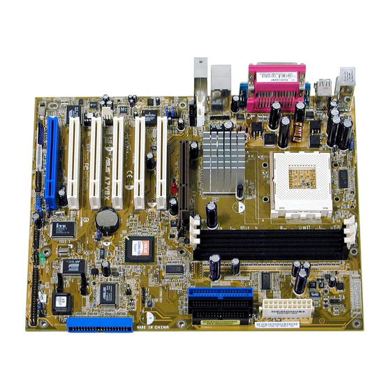
- Page 15 Below:Mic In Accelerated Graphics Port (AGP1) ® PCI1 VT6103 A7V8X-MX SE VT8235CE PCI2 CHA_FAN1 CR2032 3V Super Lithium Cell CMOS Power SPDIF PCI3 AD1980 CLRTC CODEC CHASSIS USBPWR56 USB56 FP_AUDIO AUX1 SB_PWR GAME PANEL ASUS A7V8X-MX SE motherboard user guide...
-
Page 16: Motherboard Components
The A7V8X-MX SE uses the Micro ATX form factor, measuring 24.5 cm (9.6 in.) x 24.5 cm (9.6 in.) - a standard fit for most Micro ATX chassis. WARNING! Unplug the power cord before installing the motherboard. Failure to do so may cause you physical injury and damage Motherboard components. -
Page 17: Onboard Led
Onboard LED The A7V8X-MX SE motherboard comes with a standby power LED. When lit, this green LED (SB_PWR) indicates that the system is ON, in sleep mode, or in soft-off mode, a reminder that you should shut down the system and unplug the power cable before removing or plugging in any motherboard component. -
Page 18: Installing The Cpu
CPU NOTCH A7V8X-MX SE AMD™ CPU A7V8X-MX SE Socket 462 Each AMD CPU has a “marked” corner. This corner is usually indicated with a notch, and/or a golden square or triangle. Refer to this indicator while orienting the CPU. A fan and heatsink should be attached to the CPU to prevent overheating. -
Page 19: Installing A Dimm
Unlocked retaining clip into place. A DDR DIMM is keyed with a notch so that it fits in only one direction. DO NOT force a DIMM into a socket to avoid damaging the DIMM. ASUS A7V8X-MX SE motherboard user guide 1-11... -
Page 20: Configuring An Expansion Card
The A7V8X-MX SE motherboard has three (3) PCI slots and one (1) Accelerated Graphics Port (AGP). The following sub-sections describe the slots and the expansion cards that they support. 1.10.1 Configuring an expansion card Some expansion cards need an IRQ to operate. Generally, an IRQ must be exclusively assigned to one function at a time. -
Page 21: Agp Slot
® A7V8X-MX SE Keyed for 1.5v A7V8X-MX SE Accelerated Graphics Port (AGP) 1.10.3 PCI slots Three 32-bit PCI slots are available on this motherboard. The slots support PCI cards such as LAN card, SCSI card, USB card, and other cards that comply with PCI specifications. - Page 22 A7V8X-MX SE 4.Frequency Selection 5.Frequency Selection A7V8X-MX SE DIP Switches The option to set the CPU core bus frequency multiple is available only on unlocked CPUs. If you are using a locked CPU, setting the switches does not produce any effect.
- Page 23 The total current consumed must NOT exceed the power supply capability (+5VSB) whether under normal condition or in sleep mode. USBPWR12 USBPWR34 +5VSB (Default) USBPWR56 ® A7V8X-MX SE +5VSB (Default) A7V8X-MX SE USB Device Wake Up ASUS A7V8X-MX SE motherboard user guide 1-15...
- Page 24 5. Plug the power cord and turn ON the computer. 6. Hold down the <Del> key during the boot process and enter BIOS setup to re-enter data. CLRTC ® A7V8X-MX SE Clear CMOS Normal A7V8X-MX SE Clear RTC RAM (Default) 1-16 Chapter 1: Product introduction...
- Page 25 2. Front panel audio connectors (10-1 pin FPAUDIO) This is an interface for front panel audio cable that allows convenient connection and control of audio devices. FP_AUDIO ® A7V8X-MX SE A7V8X-MX SE Front Panel Audio Connector ASUS A7V8X-MX SE motherboard user guide 1-17...
- Page 26 SPDIF ® A7V8X-MX SE A7V8X-MX SE Digital Audio Connector • When you input sound for S/PDIF IN, the LINE_OUT will output the sound. Mute LINE_OUT to impede sound output from S/PDIF IN. •...
- Page 27 GAME/MIDI port on the module connects a joystick or a game pad for playing games, and MIDI devices for playing or editing audio files. ® A7V8X-MX SE GAME A7V8X-MX SE Game Connector The USB/GAME module is purchased separately. ASUS A7V8X-MX SE motherboard user guide 1-19...
- Page 28 A7V8X-MX SE +12V Rotation A7V8X-MX SE 12-Volt Fan Connectors Do not forget to connect the fan cables to the fan connectors. Lack of sufficient air flow within the system may damage the motherboard components. These are not jumpers! DO NOT place jumper caps on the fan connectors! 8.
- Page 29 PIN 1. ® PIN 1 A7V8X-MX SE A7V8X-MX SE Floppy Disk Drive Connector 10. Internal audio connectors (4-pin CD, AUX) These connectors allow you to receive stereo audio input from sound sources such as a CD-ROM, TV tuner, or MPEG card.
-
Page 30: Connectors
A7V8X-MX SE SMI Lead Switch* Requires an ATX power supply. A7V8X-MX SE System Panel Connectors • System Power LED Lead (3-1 pin PLED) This 3-1 pin connector connects to the system power LED. The LED lights up when you turn on the system power, and blinks when the system is in sleep mode. -
Page 31: Chapter 2: Bios Information
This chapter tells how to change system settings through the BIOS Setup Menus. Detailed descriptions of the BIOS parameters are also provided. BIOS information... -
Page 32: Creating A Bootable Floppy Disk
• The original BIOS file for this motherboard is in the support CD. • Copy the original BIOS to a bootable floppy disk in case you need to restore the BIOS in the future. 2.1.1 Creating a bootable floppy disk 1. -
Page 33: Using The Awardbios Flash Utility
Flash utility (AWDFLASH.EXE). Follow these instructions to update the BIOS using this utility. 1. Download the latest BIOS file from the ASUS website (www.asus.com). Rename the file to *.BIN, then save it to the bootable floppy disk you created earlier. -
Page 34: Crashfree Bios Feature
To use the CrashFree BIOS feature on this motherboard, install a VGA card into one of the expansion slots before rebooting the computer. On motherboards with onboard VGA, such as the A7V8X-MX SE, you will not see the screen display when the BIOS crashes even if you reboot the computer. -
Page 35: Bios Beep Codes
The Setup program is designed to make it as easy to use as possible. It is a menu- driven program, which means you can scroll through the various sub-menus and make your selections among the predetermined choices. ASUS A7V8X-MX SE motherboard user guide... -
Page 36: Bios Menu Bar
Because the BIOS software is constantly being updated, the following BIOS setup screens and descriptions are for reference purposes only, and may not exactly match what you see on your screen. 2.3.1 BIOS menu bar The top of the screen has a menu bar with the following selections: MAIN Use this menu to make changes to the basic system configuration. -
Page 37: General Help
While moving around through the Setup program, note that explanations appear in the Item Help window located to the right of each menu. This window displays the help text for the highlighted field. ASUS A7V8X-MX SE motherboard user guide... - Page 38 Item Specific Help Legacy Diskette A: [1.44M, 3.5 in.] Change the day, month, IDE Primary Master [ST321122A] year and century. IDE Primary Slave [ASUS CDS520/A] IDE Secondary Master [None] IDE Secondary Slave [None] Case Open Warning [Enabled] Supervisor Password Clear...
-
Page 39: Main Menu
Halt On [All Errors] This field sets the system to halt on errors according to the system functions specified in each option. Configuration options: [All Errors] [No Errors] [All, But Keyboard] [All, But Diskette] [All, But Disk/Key] ASUS A7V8X-MX SE motherboard user guide... - Page 40 IDE Primary Master/Slave IDE Secondary Master/Slave IDE Primary Master Select Menu IDE HDD Auto-Detection [Press Enter] Item Specific Help IDE Primary Master [Auto] To auto-detect the Access Mode [Auto] HDD’s size, head...on this channel. Capacity 40020 MB Cylinder 19158 Head Sector Transfer Mode UDMA 2...
- Page 41 This field configures the number of read/write heads. Refer to the drive documentation to determine the correct value. To make changes to this field, set the IDE Primary Master field to [Manual] and the Access Mode to [CHS]. ASUS A7V8X-MX SE motherboard user guide 2-11...
- Page 42 Sector This field configures the number of sectors per track. Refer to the drive documentation to determine the correct value. To make changes to this field, set the Type field to [User Type HDD] and the Translation Method field to [Manual]. Transfer Mode This field selects the UDMA transfer mode.
-
Page 43: Chip Configuration
F10 : Save and Exit VGA Share Memory Size [32M] This field displays the share memory size for the onboard VGA. Configuration options: [16] [32] [64] [Disabled] tWTR [2T] Configuration options: [1T] [2T] ASUS A7V8X-MX SE motherboard user guide 2-13... - Page 44 AGP & P2P Bridge Control AGP & P2P Bridge Control Select Menu Item Specific Help AGP Aperture Size [64MB] AGP Mode [4X] AGP Driving Control [Auto] AGP Driving Value AGP Fast Write [Disabled] AGP Master 1 WS Write [Disabled] AGP Master 1 WS Read [Disabled] AGP 3.0 Calibration Cycle [Enabled]...
- Page 45 Precharge to Active (Trp) [5T] Configuration options: [2T] [3T] [4T] [5T] Active to Precharge (Tras) [7T] Configuration options: [6T] [7T] [8T] [9T] Active to CMD (Trcd) [5T] Configuration options: [2T] [3T] [4T] [5T] ASUS A7V8X-MX SE motherboard user guide 2-15...
- Page 46 DRAM Burst Lenght [4] Configuration options: [4] [8] DRAM Command Rate [2T Command] Configuration options: [2T Command] [1T Command] Write Recovery Time [3T] Configuration options: [3T] [2T] CPU & PCI Bus Control CPU & PCI Bus Control Select Menu Item Specific Help PCI1 Master 0 WS Write [Enabled] PCI2 Master 0 WS Write...
-
Page 47: Via Onchip Ide Device
[Mode 4] Primary Master/Slave UDMA [Auto] Secondary Master/Slave UDMA [Auto] UltraDMA capability allows improved transfer speeds and data integrity for compatible IDE devices. Set to Auto to for automatic configuration. Configuration options: [Auto] [Disabled] ASUS A7V8X-MX SE motherboard user guide 2-17... -
Page 48: I/O Device Configuration
2.5.2 I/O Device Configuration I/O Device Configuration Select Menu Item Specific Help Onboard FDC Controller [Enabled] Onboard Serial Port 1 [3F8/IRQ4] Onboard Parallel Port [378/IRQ7] Parallel Port Mode [ECP+EPP] ECP Mode USE DMA EPP Mode Select [EPP1.7] VIA-3058 AC97 Audio [Auto] Onboard LAN [Auto]... - Page 49 This field allows you to select the onboard MIDI port address. Configuration options: [330] [300] [290] [Disabled] MIDI Port IRQ [10] This field allows you to set the IRQ assignment of the onboard MIDI port. Configuration options: [330] [300] [290] [Disabled] ASUS A7V8X-MX SE motherboard user guide 2-19...
-
Page 50: Pci Configuration
2.5.3 PCI Configuration PCI Configuration Select Menu Resources controlled by [Auto (ESCD)] Item Specific Help IRQ Resources BIOS can automatically PCI/VGA Palette Snoop [Disabled] configure all the boot Assign IRQ for VGA [Enabled] Plug and Play Assign IRQ for USB [Enabled] compatible devices. -
Page 51: Irq Resources
The IRQ Resources sub-menu is activated when the Resources Controlled by parameter is set to [Manual]. Select [PCI Device] to assign an IRQ address to a Plug and Play device. Setting to [Reserved] reserves the IRQ address. Configuration options: [PCI Devices] [Reserved] ASUS A7V8X-MX SE motherboard user guide 2-21... - Page 52 ACPI Suspend Type [S1&S3] Select Menu Power Management [User Define] HDD Power Down [Disabled] Item Specific Help Suspend Mode [Disabled] Video-off Option [Suspend -> Off] Select the ACPI state AC Loss Auto Restart [Auto] used for System Video Off Method [V/H SYNC+Blank] Suspend.
-
Page 53: Power Up Control
[V/H Sync+Blank] [DPMS support] C.O.P. Control [85 degree] Sets the threshold value for the CPU temperature. The ASUS CPU Overheating Protection (C.O.P.) feature of this motherboard automatically shuts down the system when the CPU temperature reaches or exceeds the threshold value. - Page 54 PS2KB Wakeup Select [Hot Key] This parameter allows you to use specific keys on the keyboard to turn on the system. This feature requires an ATX power supply that provides at least 1A on the +5VSB lead. Configuration options: [Disabled] [Ctrl+F1]...[Ctrl+F12] [Power] [Wake] [Any Key] PS2KB Wakeup from S3/S4/S5 [Disabled] When set to [Enabled], this parameter allows you to use the PS/2 keyboard to turn...
-
Page 55: Hardware Monitor
(RPM). If any of the fans is not connected to the motherboard, that field shows 0RPM. Vcore, +3.3V, +5V, +12V The onboard hardware monitor automatically detects the voltage output through the onboard voltage regulators. ASUS A7V8X-MX SE motherboard user guide 2-25... - Page 56 Select Menu First Boot Device [HDD-0] Second Boot Device [CDROM] Item Specific Help Third Boot Device [Floppy] Fourth Boot Device [Disabled] Select your boot device Plug and Play OS [Yes] priority. Reset Configuration Data [Disabled] Quick Power On Self Test [Enabled] Boot Up Floppy Seek [Disabled]...
-
Page 57: Exit Without Saving
Setup menus. When you select this option or if you press <F7>, a confirmation window appears. Select [Yes] to load optimized values. Select Save & Exit or make other changes before saving the values to the non-volatile RAM. ASUS A7V8X-MX SE motherboard user guide 2-27... -
Page 58: Discard Changes
Discard Changes This option allows you to discard the selections you made and restore the previously saved values. After selecting this option, a confirmation appears. Select [Yes] to discard any changes and load the previously saved values. Save Changes This option saves your selections without exiting the Setup program. You can then return to other menus and make further changes. -
Page 59: Chapter 3: Software Support
This chapter describes the contents of the support CD that comes with the motherboard package. Software support... -
Page 60: Running The Support Cd
The contents of the support CD are subject to change at any time without notice. Visit the ASUS website for updates. 3.2.1 Running the support CD To begin using the support CD, place the CD into the optical drive. The CD automatically displays the Drivers menu if Autorun is enabled in your computer. -
Page 61: Drivers Menu
Click this item to install the VIA 10/100Mb Fast Ethernet driver for the onboard local area network (LAN) controller. USB 2.0 Driver This item installs the USB 2.0 driver. Some items appear only on specific operating system versions. ASUS A7V8X-MX motherboard user manual... -
Page 62: Utilities Menu
This utility helps you keep your computer at a healthy operating condition. Install ASUS Update The ASUS Update is a utility that allows you to update the motherboard BIOS and drivers. This utility requires an Internet connection either through a network or an Internet Service Provider (ISP). -
Page 63: Asus Contact Information
3.2.4 ASUS contact information Click the Contact tab to display ASUS contact information. Screen display and driver options may not be the same for other operating system versions. ASUS A7V8X-MX motherboard user manual... - Page 64 Chapter 3: Software support...
Need help?
Do you have a question about the A7V8X-MX SE and is the answer not in the manual?
Questions and answers