Asus Motherboard A7V8X User Manual
Asus motherboard user guide
Hide thumbs
Also See for Motherboard A7V8X:
- Manual de démarrage rapide (17 pages) ,
- User manual (132 pages)
Table of Contents
Advertisement
Quick Links
Advertisement
Table of Contents

Related Manuals for Asus Motherboard A7V8X


Summary of Contents for Asus Motherboard A7V8X
- Page 1 A7V8X User Guide...
- Page 2 Product warranty or service will not be extended if: (1) the product is repaired, modified or altered, unless such repair, modification of alteration is authorized in writing by ASUS; or (2) the serial number of the product is defaced or missing.
-
Page 3: Table Of Contents
About this guide ... viii How this guide is organized ... viii Conventions used in this guide ... ix Where to find more information ... ix ASUS contact information ... x A7V8X specifications summary ... xi Chapter 1: Product introduction 1.1 Welcome! ... 1-1 1.2 Package contents ... - Page 4 3.3 Powering off the computer ... 3-4 Chapter 4: BIOS setup 4.1 Managing and updating your BIOS ... 4-1 4.1.1 Using ASUS EZ Flash to update the BIOS ... 4-1 4.1.2 Using AFLASH to update the BIOS ... 4-3 4.2 BIOS Setup program ... 4-7 4.2.1...
- Page 5 5.2.1 Running the support CD ... 5-1 5.2.2 Drivers menu ... 5-2 5.2.3 Utilities menu ... 5-3 5.2.4 ASUS Contact Information ... 5-6 5.2.5 Other information ... 5-7 5.3 Software information ... 5-9 5.3.1 ASUS Update ... 5-9 5.3.2 ASUS MyLogo2™ ... 5-10 5.3.3...
-
Page 6: Canadian Department Of Communications Statement
FCC/CDC statements Federal Communications Commission Statement This device complies with FCC Rules Part 15. Operation is subject to the following two conditions: • This device may not cause harmful interference, and • This device must accept any interference received including interference that may cause undesired operation. -
Page 7: Electrical Safety
Safety information Electrical safety • To prevent electrical shock hazard, disconnect the power cable from the electrical outlet before relocating the system. • When adding or removing devices to or from the system, ensure that the power cables for the devices are unplugged before the signal cables are connected. -
Page 8: About This Guide
About this guide This user guide contains the information you need when installing the ASUS A7V8X motherboard. How this guide is organized This manual contains the following parts: • Chapter 1: Product introduction This chapter describes the features of the A7V8X motherboard. It includes brief descriptions of the special attributes of the motherboard and the new technology it supports. -
Page 9: Conventions Used In This Guide
1. ASUS Websites The ASUS websites worldwide provide updated information on ASUS hardware and software products. The ASUS websites are listed in the ASUS Contact Information on page x. 2. Optional Documentation Your product package may include optional documentation, such as warranty flyers, that may have been added by your dealer. -
Page 10: Asus Contact Information
Desktop/Server (Tel): +886-2-2890-7123 (English) Support Fax: +886-2-2890-7698 Support Email: tsd@asus.com.tw Web Site: www.asus.com.tw Newsgroup: cscnews.asus.com.tw ASUS COMPUTER INTERNATIONAL (America) Address: 6737 Mowry Avenue, Mowry Business Center, Building 2, Newark, CA 94560, USA General Fax: +1-510-608-4555 General Email: tmd1@asus.com Technical Support... -
Page 11: A7V8X Specifications Summary
Maximum 3 GB unbuffered PC2100/1600 non-ECC SDRAM Memory.(Note: PC2700 maximum to 2 DIMM support only. PC3200 maximum to 1 DIMM support only.) Visit the ASUS website for the latest qualified DDR400/DDR333 module list Expansion slots 1 x AGP 8X 6 x PCI (one shared with ASUS BlueMagic PCI slot.) - Page 12 1 x USB 2.0 connector supports additional 2 USB 2.0 ports 2 x Serial ATA port (on serial ATA model only) 4Mb Flash ROM, Award BIOS, TCAV, PnP, DMI2.0, WfM2.0, SM BIOS2.3, Multi-language BIOS, ASUS EZ Flash, ASUS MyLogo2 PCI 2.2, USB 2.0 WfM 2.0.
-
Page 13: Chapter 1: Product Introduction
Chapter 1 This chapter describes the features of the ASUS A7V8X motherboard. It includes brief explanations of the special attributes of the motherboard and the new technology it supports. Product introduction... -
Page 14: Chapter Summary
Chapter summary Welcome! ... 1-1 Package contents ... 1-1 Special features ... 1-2 Motherboard overview ... 1-6 ASUS A7V8X motherboard... -
Page 15: Welcome
A processors. Based on the advanced VIA KT400 chipset with DDR 400 support, the ASUS A7V8X also features AGP 8X, serial ATA, USB 2.0 as well as optional 6-channel audio, Gigabit LAN and 1394. Unique ASUS features such as ASUS C.O.P., Q-Fan and MyLogo2 and more are included to... -
Page 16: Special Features
Special features 1.3.1 Product highlights 333MHz FSB Athlon XP CPU support AMD’s Athlon XP 2700+ and all follow-up CPUs now support 333MHz Front Side Bus (FSB) for increased application program productivity and enhanced digital media experience. AGP 8X support AGP 8X (AGP 3.0) is the next generation VGA interface specification that enables enhanced graphics performance with high bandwidth speeds up to 2.12 GB/s. -
Page 17: Asus Mylogo2
PC shuts down automatically. ASUS POST Reporter™ (optional) A7V8X offers a new exciting feature called the ASUS POST Reporter™ to provide friendly voice messages and alerts during the Power-On Self-Tests (POST). Through the system’s internal speaker, or an added external speaker, you will hear the messages informing you of the system boot status and causes of boot errors, if any. - Page 18 ASUS EZ Flash BIOS With the ASUS EZ Flash, you can easily update the system BIOS even before loading the operating system. No need to use a DOS-based utility or boot from a floppy disk. 6-channel Audio (optional) The A7V8X uses an onboard Realtek CODEC that lets you enjoy high- quality 6-channel audio without having to buy advanced sound cards.
- Page 19 ASUS A7V8X motherboard user guide...
-
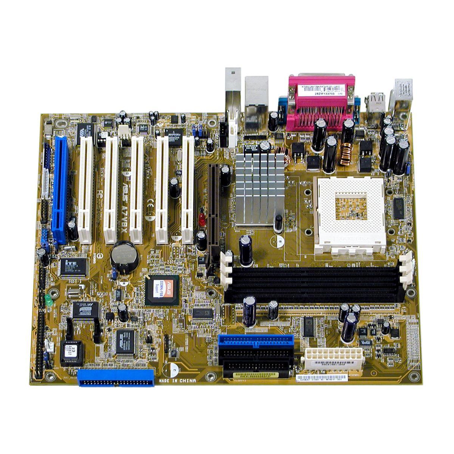
Page 20: Motherboard Overview
15. Super I/O controller IEEE 1394 connector 17. IEEE 1394 controller 18. PCI slots (Note: The ASUS BlueMagic PCI slot works as a normal PCI slot and it is also compatible with the ASUS proprietary wireless card - Spacelink B&W) See page 1-8 for the specifications of each major component. - Page 21 ASUS A7V8X motherboard user guide 14 13...
-
Page 22: Core Specifications
DDR DIMMs.(Note: PC2700 maximum to 2 DIMM support only. PC3200 maximum to 1 DIMM support only.) Visit the ASUS website (www.asus.com) for the latest qualified DDR400 module list. ATX power connector. This 20-pin connector connects to an ATX +12V power supply. The power supply must have at least 1A on the +5V standby lead (+5VSB). - Page 23 PCI cards like SCSI or LAN cards with 133MB/s maximum throughput. (Note: The ASUS BlueMagic PCI slot works as a normal PCI slot and it is also compatible with the ASUS proprietary wireless card - Spacelink B&W) Audio CODEC . The Realtek ALC650 is an AC’97 compliant audio CODEC for PC multimedia systems.
- Page 24 Gigabit LAN or LAN controller. The BroadCom Gigabit LAN delivers transfer rates up to ten times faster than conventional 10/ 100 Ethernet connections. Ideal for handling large amounts of data such as video, audio and voice. (on LAN models only) AGP slot.
-
Page 25: Chapter 2: Hardware Information
Chapter 2 This chapter describes the hardware setup procedures that you have to perform when installing system components. It includes details on the switches, jumpers, and connectors on the motherboard. Hardware information... - Page 26 Chapter summary Motherboard installation ... 2-1 Motherboard layout ... 2-2 Before you proceed ... 2-3 Central Processing Unit (CPU) ... 2-4 System memory ... 2-6 Expansion slots ... 2-11 Switches and jumpers ... 2-14 Connectors ... 2-18 ASUS A7V8X motherboard...
-
Page 27: Motherboard Installation
Place nine (9) screws into the holes indicated by circles to secure the motherboard to the chassis. Do not overtighten the screws! Doing so may damage the motherboard. Place this side towards the rear of the chassis ASUS A7V8X motherboard user guide... -
Page 28: Motherboard Layout
PCI2 Chipset PCI3 CR2032 3V Lithium Cell A7V8X ® CMOS Power CLRTC1 PCI4 PCI5 PCI6 USB56 SMARTCARD1 WPCI_USB1 GAME1 Chapter 2: Hardware information SMB_CON1 TRPWR1 ASUS ASIC with Hardware Monitor SEC_SATA1 4Mbit Firmware PRI_SATA1 CHASSIS1 SB_PWR1 CHA_FAN1 IR_CON1 AFPANEL1 PANEL1... -
Page 29: Before You Proceed
1.5V AGP slot, this LED lights up thus preventing the system to power up. This LED remains off if you plug in a 1.5V AGP card. A7V8X ® A7V8X Onboard LED ASUS A7V8X motherboard user guide AGP_WARN1 Incorrect Correct AGP Card AGP Card... -
Page 30: Central Processing Unit (Cpu)
Central Processing Unit (CPU) 2.4.1 Overview The motherboard provides a Socket A (462) for CPU installation. AMD processors offer gigahertz speeds to support all the latest computing platforms and applications. The A7V8X supports Athlon processors. ® A7V8X A7V8X Socket A Each AMD CPU has a “marked”... -
Page 31: Installing The Cpu
CPU, make sure that exposed CPU capacitors do not touch the heatsink, or damage may occur! Do not neglect to set the correct Bus Frequency and leave the CPU Multiple setting at default to avoid start-up problems. ASUS A7V8X motherboard user guide... -
Page 32: System Memory
System memory 2.5.1 Overview The motherboard comes with three Double Data Rate (DDR) Dual Inline Memory Module (DIMM) sockets. These sockets support up to 3GB system memory using 184-pin unbuffered non-ECC PC3200/PC2700/ 2100/1600 DIMMs. (Note: DDR400 supports one (1) socket only. DDR333 supports two (2) sockets only.) ®... -
Page 33: Memory Configurations
DDR400 DIMMs listed above. Other DDR DIMMs manufactured by other vendors may not be suitable for this motherboard. Visit the ASUS website (www.asus.com) for the latest qualified vendor DDR400 module list. ASUS A7V8X motherboard user guide... -
Page 34: Installing A Dimm
2.5.3 Installing a DIMM Make sure to unplug the power supply before adding or removing DIMMs or other system components. Failure to do so may cause severe damage to both the motherboard and the components. Follow these steps to install a DIMM. 1. -
Page 35: Removing A Dimm
1. Simultaneously press the retaining clips outward to unlock the DIMM. Support the DIMM lightly with your fingers when pressing the retaining clips. The DIMM might get damaged when it flips out with extra force. 2. Remove the DIMM from the socket. ASUS A7V8X motherboard user guide... - Page 36 2-10 Chapter 2: Hardware information...
-
Page 37: Expansion Slots
1. Turn on the system and change the necessary BIOS settings, if any. See Chapter 4 for information on BIOS setup. 2. Assign an IRQ to the card. Refer to the tables on the next page. 3. Install the software drivers for the expansion card. ASUS A7V8X motherboard user guide 2-11... -
Page 38: Irq Assignments For This Motherboard
Standard Interrupt Assignments Priority These IRQs are usually available for ISA or PCI devices. IRQ assignments for this motherboard PCI slot 1 PCI slot 2 PCI slot 3 PCI slot 4 PCI slot 5 PCI slot 6 AGP slot USB 1.1 UHCI 1 USB 1.1 UHCI 2 USB 1.1 UHCI 3 USB 2.0 EHCI... -
Page 39: Pci Slots
LAN card, SCSI card, USB card, and other cards that comply with PCI specifications. The following figure shows a LAN card installed on a PCI slot. The ASUS BlueMagic PCI slot works as a normal PCI slot and it is also compatible with the ASUS proprietary wireless card - SpaceLink B&W. - Page 40 Jumpers 1. Keyboard power (3-pin KBPWR1) This jumper allows you to enable or disable the keyboard wake-up feature. Set this jumper to pins 2-3 (+5VSB) if you wish to wake up the computer when you press a key on the keyboard (the default value is [Disabled]).
- Page 41 Otherwise, the system does not power up. 2. The total current consumed must NOT exceed the power supply capability (+5VSB) whether under normal condition or in sleep mode. ® A7V8X A7V8X USB Device Wake Up ASUS A7V8X motherboard user guide USBPWR_12 USBPWR_34 +5VSB (Default) USBPWR_56 +5VSB...
- Page 42 This jumper connects one set of USB signal to PCI slot 6 to support ASUS wireless card. Since USB signals are used by some reserved pins of PCI slot and to ensure the compatibility of the other PCI cards, it should be kept at default setting except when ASUS wireless card is used.
-
Page 43: Connectors
(Pin 5 is removed to prevent incorrect insertion when using ribbon cables with pin 5 plug). A7V8X ® A7V8X Floppy Disk Drive Connector ASUS A7V8X motherboard user guide IDELED1 TIP: If the case-mounted LED does not light, try reversing the 2-pin plug. FLOPPY1... - Page 44 3. IDE connectors (40-1 pin IDE1, IDE2) This connector supports the provided UltraDMA/133/100/66 IDE hard disk ribbon cable. Connect the cable’s blue connector to the primary (recommended) or secondary IDE connector, then connect the gray connector to the UltraDMA/133/100/66 slave device (hard disk drive) and the black connector to the UltraDMA/133/100/66 master device.
- Page 45 ATA and Serial ATA connectors. For RAID 0, you may choose any two or three connectors of Parallel ATA and Serial ATA connectors. ASUS A7V8X motherboard user guide NOTE: Orient the red markings (usually zigzag) on the IDE ribbon cable to PIN 1.
- Page 46 5. Chassis intrusion connector (4-1 pin CHASSIS1) This lead is for a chassis designed with intrusion detection feature. This requires an external detection mechanism such as a chassis intrusion sensor or microswitch. When you remove any chassis component, the sensor triggers and sends a high-level signal to this lead to record a chassis intrusion event.
- Page 47 This connector accommodates an optional Smart Card Reader that allows you to conveniently make transactions such as financial, health care, telephony, or traveling services through a Smart Card user interface software. ® A7V8X A7V8X Smartcard Connector ASUS A7V8X motherboard user guide ATXPWR1 +3.3VDC +3.3VDC -12.0VDC +3.3VDC PS_ON# +5.0VDC...
- Page 48 9. CPU, Chassis, and Power Fan Connectors (3-pin CPU_FAN1, PWR_FAN1, CHA_FAN1) The fan connectors support cooling fans of 350mA~740mA (8.88W max.) or a total of 1A~2.22A (26.64W max.) at +12V. Connect the fan cables to the fan connectors on the motherboard, making sure that the black wire of each cable matches the ground pin of the connector.
- Page 49 The GAME/MIDI port on the module connects a joystick or a game pad for playing games, and MIDI devices for playing or editing audio files. ® A7V8X A7V8X Game Connector ASUS A7V8X motherboard user guide USB_56 (Blue) GAM1 2-23...
- Page 50 This connector allows you to connect an optional ASUS iPanel, an easy-to-access drive bay with front I/O ports and status LEDs. If you are not using an ASUS iPanel, you can connect an optional wireless transmitting and receiving infrared module to the SIR connector.
- Page 51 IEEE 1394 connector on-board (IEEEE1394_1). For IEEE 1394 devices that doesn’t require internal power, you may connect to the white IEEE 1394 connector (IEEE1394_2) on-board. ® A7V8X A7V8X IEEE-1394 Connectors ASUS A7V8X motherboard user guide blue IEEE1394 connector IEEE1394_1 IEEE1394_2 blue IEEE 1394 connector 2-25...
- Page 52 16. Digital audio connector (6-1 pin SPDIF1) (on audio models only) This connector is for the bundled S/PDIF audio module that allows digital instead of analog sound output. Connect one end of the audio cable to the S/PDIF In/Out connector on the motherboard, and the other end to the S/PDIF module.
- Page 53 Use the ten pins as shown in Back View and connect a ribbon cable from the module to the motherboard SIR connector according to the pin definitions. A7V8X ® A7V8X Infrared Module Connector ASUS A7V8X motherboard user guide SEC_SATA1 PRI_SATA1 Standard Infrared (SIR) Front View Back View IRTX...
-
Page 54: System Panel Connector
20. System panel connector (20-pin PANEL1) This connector accommodates several system front panel functions. ® A7V8X A7V8X System Panel Connectors • System Power LED Lead (3-1 pin PLED) This 3-1 pin connector connects to the system power LED. The LED lights up when you turn on the system power, and blinks when the system is in sleep mode. -
Page 55: Chapter 3: Powering Up
Chapter 3 This chapter describes the power up sequence and gives information on the BIOS beep codes. Powering up... -
Page 56: Chapter Summary
Chapter summary Starting up for the first time ... 3-1 Vocal POST Messages ... 3-2 Powering off the computer ... 3-4 ASUS A7V8X motherboard... -
Page 57: Vocal Post Messages
High frequency beeps when system is working You will not hear the BIOS beeps when the ASUS POST Reporter™ is enabled. You will hear the vocal POST messages instead. 7. At power on, hold down <Delete> to enter BIOS Setup. Follow the instructions in Chapter 4. -
Page 58: Vocal Post Messages
Vocal POST Messages This motherboard includes the Winbond speech controller to support a special feature called the ASUS POST Reporter™. This feature gives you vocal POST messages and alerts to inform you of system events and boot status. In case of a boot failure, you will hear the specific cause of the problem. - Page 59 System completed Power-On Self Test • No action required Computer now booting from operating • No action required system You may disable the ASUS POST Reporter™ in the BIOS setup. See section “4.4.2 I/O Device Configuration”. ASUS A7V8X motherboard user guide Action •...
-
Page 60: Powering Off The Computer
Powering off the computer You must first exit the operating system and shut down the system before switching off the power. For ATX power supplies, you can press the ATX power switch after exiting or shutting down the operating system. If you use Windows 95/98/2000/XP, click the Start button, click Shut Down, then click the OK button to shut down the computer. -
Page 61: Chapter 4: Bios Setup
Chapter 4 This chapter tells how to change system settings through the BIOS Setup menus. Detailed descriptions of the BIOS parameters are also provided. BIOS setup... - Page 62 Chapter summary Managing and updating your BIOS ... 4-1 BIOS Setup program ... 4-7 Main Menu ... 4-10 Advanced Menu ... 4-17 Power Menu ... 4-27 Boot Menu ... 4-33 Exit Menu ... 4-35 ASUS A7V8X motherboard...
-
Page 63: Managing And Updating Your Bios
BIOS later. 4.1.1 Using ASUS EZ Flash to update the BIOS The ASUS EZ Flash feature allows you to easily update the BIOS without having to go through the long process of booting from a diskette and using a DOS-based utility. The EZ Flash is built-in the BIOS firmware so it is accessible by simply pressing <Alt>... - Page 64 5. At the prompt, “Please Enter File Name for NEW BIOS: _” BIOS file name that you downloaded from the ASUS website, then press <Enter>. EZ Flash will automatically access drive A to look for the file name that you typed. When found, the following message appears on screen.
-
Page 65: Using Aflash To Update The Bios
4. In DOS mode, type A:\AFLASH <Enter> to run AFLASH. If the word “unknown” appears after Flash Memory:, the memory chip is either not programmable or is not supported by the ACPI BIOS and therefore, cannot be programmed by the Flash Memory Writer utility. ASUS A7V8X motherboard user guide... - Page 66 5. Select 1. Save Current BIOS to File from the Main menu and press <Enter>. The Save Current BIOS To File screen appears. 6. Type a filename and the path, for example, A:\XXX-XX.XXX, then press <Enter>. Chapter 4: BIOS Setup...
- Page 67 BIOS revision will solve your problems. Careless updating may result to more problems with the motherboard! 1. Download an updated ASUS BIOS file from the Internet (WWW or FTP) (see ASUS CONTACT INFORMATION on page x for details) and save to the boot floppy disk you created earlier.
- Page 68 If the Flash Memory Writer utility is not able to successfully update a complete BIOS file, the system may not boot. If this happens, call the ASUS service center for support. Chapter 4: BIOS Setup...
-
Page 69: Bios Setup Program
Because the BIOS software is constantly being updated, the following BIOS setup screens and descriptions are for reference purposes only, and may not exactly match what you see on your screen. ASUS A7V8X motherboard user guide... -
Page 70: Bios Menu Bar
4.2.1 BIOS menu bar The top of the screen has a menu bar with the following selections: MAIN Use this menu to make changes to the basic system configuration. ADVANCED Use this menu to enable and make changes to the advanced features. -
Page 71: General Help
While moving around through the Setup program, note that explanations appear in the Item Specific Help window located to the right of each menu. This window displays the help text for the currently highlighted field. ASUS A7V8X motherboard user guide... -
Page 72: Main Menu
Main Menu When you enter the Setup program, the following screen appears. System Time [XX:XX:XX] Sets the system to the time that you specify (usually the current time). The format is hour, minute, second. Valid values for hour, minute and second are Hour: (00 to 23), Minute: (00 to 59), Second: (00 to 59). - Page 73 Configuration options: [All Errors] [No Error] [All but Keyboard] [All but Disk] [All but Disk/Keyboard] Installed Memory [XXX MB] This field automatically displays the amount of conventional memory detected by the system during the boot process. ASUS A7V8X motherboard user guide 4-11...
-
Page 74: Primary And Secondary Master/Slave
4.3.1 Primary and Secondary Master/Slave Type [Auto] Select [Auto] to automatically detect an IDE hard disk drive. If automatic detection is successful, Setup automatically fills in the correct values for the remaining fields on this sub-menu. If automatic detection fails, this may be because the hard disk drive is too old or too new. - Page 75 After making your selections on this sub-menu, press the <Esc> key to return to the Main menu. When the Main menu appears, the hard disk drive field displays the size for the hard disk drive that you configured. ASUS A7V8X motherboard user guide 4-13...
- Page 76 Translation Method [LBA] Select the hard disk drive type in this field. When Logical Block Addressing (LBA) is enabled, the 28-bit addressing of the hard drive is used without regard for cylinders, heads, or sectors. Note that LBA Mode is necessary for drives with more than 504MB storage capacity.
- Page 77 IDE devices. Set to [Disabled] to suppress Ultra DMA capability. To make changes to this field, set the Type field to [User Type HDD]. Configuration options: [0] [1] [2] [3] [4] [5] [Disabled] ASUS A7V8X motherboard user guide 4-15...
-
Page 78: Keyboard Features
4.3.2 Keyboard Features Boot Up NumLock Status [On] This field enables users to activate the Number Lock function upon system boot. Configuration options: [Off] [On] Keyboard Auto-Repeat Rate [6/Sec] This controls the speed at which the system registers repeated keystrokes. Options range from 6 to 30 characters per second. -
Page 79: Advanced Menu
CPU Frequency Multiple unlocked processor. If your processor frequency multiple is locked, you cannot change the setting of this item. ASUS A7V8X motherboard user guide (when CPU Speed is set to [Manual]) is accessible only if you have an 4-17... - Page 80 CPU External Frequency (MHz) (when CPU Speed is set to [Manual]) This feature tells the clock generator what frequency to send to the system bus and PCI bus. The bus frequency (external frequency) multiplied by the bus multiple equals the CPU speed. Memory Frequency (Mhz) [Auto] This field allows you to select a higher memory frequency for better system performance.
- Page 81 OS/2 Onboard Memory > 64M [Disabled] When using OS/2 operating systems with installed DRAM of greater than 64MB, you need to set this option to [Enabled]. Otherwise, leave to the default setting [Disabled]. Configuration options: [Disabled] [Enabled] ASUS A7V8X motherboard user guide 4-19...
-
Page 82: Chip Configuration
4.4.1 Chip Configuration SDRAM Configuration [By SPD] This parameter allows you to set the optimal timings for items 2–5, depending on the memory modules that you are using. The default setting is [By SPD], which configures items 2–5 by reading the contents in the SPD (Serial Presence Detect) device. - Page 83 AGP Drive N Control [E] Configuration options: [0][1][2][3][4][5][6][7][8][9][A][B][C][D][E][F] AGP Drive P Control [F] Configuration options: [0][1][2][3][4][5][6][7][8][9][A][B][C][D][E][F] AGP performance control [Disabled] Configuration options: [Disabled] [Enabled] AGP Fast Write control [Disabled] Configuration options: [Disabled] [Enabled] ASUS A7V8X motherboard user guide (value depends on SDRAM SPD) 4-21...
- Page 84 Video Memory Cache Mode [UC] USWC (uncacheable, speculative write combining) is a new cache technology for the video memory of the processor. It can greatly improve the display speed by caching the display data. You must set this to UC (uncacheable) if your display card does not support this feature, otherwise the system may not boot.
-
Page 85: I/O Device Configuration
Configuration options: [3F8H/IRQ4] [2F8H/IRQ3] [3E8H/IRQ4] [2E8H/ IRQ10] [Disabled] UART2 Use As [COM Port] This field allows you to select the device on which to assign UART2. Configuration options: [COM Port] [IR] [Smart Card Reader] ASUS A7V8X motherboard user guide 4-23... - Page 86 MIDI ports must have different addresses. Configuration options: [330H-331H] [300H-301H] [Disabled] Speech POST Reporter [Enabled] This field enables or disables the ASUS POST Reporter™ feature. See section “1.3 Special Features” and “3.2 Vocal POST messages” for more information. Configuration options: [Disabled] [Enabled] The buzzer warning sound is disabled if you enable the POST reporter.
-
Page 87: Pci Configuration
This field allows you to select the USB port that you wish to activate. Configuration options: [Disabled] [Enabled] Primary VGA BIOS [PCI VGA Card] This field allows you to select the primary graphics card. Configuration options: [PCI VGA Card] [AGP VGA Card] ASUS A7V8X motherboard user guide 4-25... -
Page 88: Pci Irq Resource Exclusion
Onboard LAN Boot ROM This field allows you to enable or disable the onboard LAN Boot ROM. Configuration options: [Disabled] [Enabled] Onboard ATA device First [No] This field allows you to select the onboard ATA first. Configuration options: [No] [Yes] 4.4.3.1 PCI IRQ Resource Exclusion IRQ XX Reserved [No/ICU] These fields indicate whether or not the displayed IRQ for each field is... -
Page 89: Power Menu
Configuration options: [User Defined] [Disabled] [Min Saving] [Max Saving] Video Off Option [Suspend -> Off ] This field determines when to activate the video off feature for monitor power management. Configuration options: [Always On] [Suspend -> Off] ASUS A7V8X motherboard user guide 4-27... -
Page 90: Suspend Mode [Disabled]
Video Off Method [DPMS OFF] This field defines the video off features. The Display Power Management System (DPMS) feature allows the BIOS to control the video display card if it supports the DPMS feature. [Blank Screen] only blanks the screen. Use this for monitors without power management or “green”... -
Page 91: Power Up Control
Thus, connection cannot be made on the first try. Turning an external modem off and then back on while the computer is off causes an initialization string that turns the system power on. ASUS A7V8X motherboard user guide 4-29... - Page 92 Wake/Power Up By PS/2 Keyboard [Space Bar] This parameter allows you to use specific keys on the keyboard to turn on the system. This feature requires an ATX power supply that provides at least 1A on the +5VSB lead. Configuration options: [Disabled] [Space Bar] [Ctrl-Esc] [Power Key] Wake/Power Up By PS/2 Mouse [Disabled] When set to [Enabled], this parameter allows you to use the PS/2 mouse...
-
Page 93: Hardware Monitor
The onboard hardware monitor automatically detects and displays the CPU, chassis, and power fan speeds in rotations per minute (RPM). If any of the fans is not connected to the motherboard, the specific field shows N/A. ASUS A7V8X motherboard user guide 4-31... - Page 94 The onboard hardware monitor automatically detects the voltage output through the onboard voltage regulators. Q-Fan Control [Disabled] This item allows you to enable or disable the ASUS Q-Fan feature that smartly adjusts the fan speeds for more efficient system operation. When this field is set to [Enabled], the...
-
Page 95: Boot Menu
This field allows you to select which ATAPI CD-ROM drive to use in the boot sequence. Pressing [Enter] will show the product IDs of all your connected ATAPI CD-ROM drives. Other Boot Device Select [INT18 Device (Network)] Configuration options: [Disabled] [SCSI Boot Device] [INT18 Device (Network)] ASUS A7V8X motherboard user guide 4-33... -
Page 96: Full Screen Logo [Enabled]
This allows you to enable or disable the full screen logo display feature. Configuration options: [Disabled] [Enabled] Make sure that the above item is set to [Enabled] if you wish to use the ASUS MyLogo2™ feature. Interrupt Mode [APIC] The Advanced Programmable Interrupt Controller (APIC) setting allows you to distribute interrupt routings other than the 16 IRQs. -
Page 97: Exit Menu
Select this option only if you do not want to save the changes that you made to the Setup program. If you made changes to fields other than system date, system time, and password, the BIOS asks for a confirmation before exiting. ASUS A7V8X motherboard user guide 4-35... -
Page 98: Discard Changes
Load Setup Defaults This option allows you to load the default values for each of the parameters on the Setup menus. When you select this option or if you press <F5>, a confirmation window appears. Select [Yes] to load default values. -
Page 99: Chapter 5: Software Support
Chapter 5 This chapter describes the contents of the support CD that comes with the motherboard package. Software support... - Page 100 Chapter summary Install an operating system ... 5-1 Support CD information ... 5-1 Software information ... 5-9 Using the Promise Chip for RAID 0 or 1 ... 5-26 Manual Installation of IDE/RAID drivers ... 5-34 ASUS A7V8X motherboard...
-
Page 101: Install An Operating System
The contents of the support CD are subject to change at any time without notice. Visit the ASUS website for updates. 5.2.1 Running the support CD To begin using the support CD, simply insert the CD into your CD-ROM drive. -
Page 102: Drivers Menu
5.2.2 Drivers menu The drivers menu shows the available device drivers if the system detects installed devices. Install the necessary drivers to activate the devices. VIA 4 in 1 drivers This item installs the following drivers: - VIA Registry (INF) driver - VIA AGP VxD driver - VIA ATAPI vendor support driver - VIA PCI IRQ Miniport driver. - Page 103 Manager button to display the Device Manager window. 3. On the Device Manager window, click the plus sign (+) opposite the Network adapters item to show the ASUSTeK/BroadCom 440x 10/100 Integrated Controller. Double-click the item. ASUS A7V8X motherboard user guide...
- Page 104 4. On the window that appears, click the item Wake Up Capabilities under Property. The default value is Wake Up Frame. The Wake Up Frame setting wakes up the system from S1, S3, and S4 sleep modes. 5. Click the arrow under Value to set to Magic Frame.
-
Page 105: Utilities Menu
This program allows you to download the latest version of the BIOS from the ASUS website. Before using the ASUS Update, make sure that you have an Internet connection so you can connect to the ASUS website. Microsoft Direct X 8.0 Driver This item installs the Microsoft V8.0 driver. -
Page 106: Asus Contact Information
FastTrak Mirrored (RAID 1) or Striped/Mirrored (RAID 0/1) disk array. Winbond Voice Editor This program is for recording and customizing wave files for the ASUS POST Reporter™. Use this program if you wish to change the default vocal POST messages. See section “3.2 Vocal POST messages” for a list of the default messages. -
Page 107: Other Information
CD. This section shows the pop-up windows that appear when you click the icons. Motherboard Info The window displays the general specifications of the A7V8X motherboard. Browse this CD The window displays the support CD contents in graphical format. ASUS A7V8X motherboard user guide... -
Page 108: Technical Support Form
Technical Support Form The window displays the ASUS Technical Support Request Form that you have to fill up when requesting technical support. Filelist The window displays the contents of the support CD and a brief description of each in text format. -
Page 109: Software Information
This section provides details on the software applications that the motherboard supports. 5.3.1 ASUS Update The ASUS Update is a utility that allows you to update the motherboard BIOS and drivers. This utility requires an Internet connection either through a network or an Internet Service Provider (ISP). -
Page 110: Asus Mylogo2
5.3.2 ASUS MyLogo2™ The ASUS MyLogo2™ is automatically installed when you install the ASUS Update utility from the software menu. See section “5.2.3 Software menu”. Before using ASUS MyLogo2 feature, use the AFLASH utility to make a copy of your original BIOS file, or obtain the latest BIOS version from the ASUS website. - Page 111 MyLogo2 directly from the Windows Start menu to change your BIOS boot logo. After you have modified the BIOS file with the new logo, use the ASUS Update utility to upload the new BIOS into the EEPROM. ASUS A7V8X motherboard user guide...
-
Page 112: Asus Pc Probe
, and then click Programs ASUS Utility Probe Vx.xx The PC Probe icon appears on the taskbar system tray indicating that ASUS PC Probe is running. Clicking the icon allows you to see the status of your PC. 5-12 Chapter 5: Software support... - Page 113 Fan Monitor Shows the PC fan rotation. Fan Warning threshold adjustment (Move the slider up to increase the threshold level or down to decrease the threshold level) Voltage Monitor Shows the PC voltages. ASUS A7V8X motherboard user guide 5-13...
- Page 114 Settings Lets you set threshold levels and polling intervals or refresh times of the PC’s temperature, fan rotation, and voltages. CPU Cooling System Setup Lets you select when to enable software CPU cooling. When When CPU Overheated is selected, the CPU cooling system is enabled whenever the CPU temperature reaches the threshold value.
- Page 115 PC, such as CPU type, CPU speed, and internal/external frequencies, and memory size. Utility Lets you run programs outside of the ASUS Probe modules. To run a program, click Execute Program NOTE: This feature is currently unavailable. ASUS A7V8X motherboard user guide...
- Page 116 ASUS PC Probe Task Bar Icon Right clicking the PC Probe icon brings up a menu to open or exit ASUS PC Probe and pause or resume all system monitoring. When the ASUS PC Probe senses a problem with your PC,...
-
Page 117: E-Color 3Deep
3Deep Control Panel program from the 3Deep Applications group on the menu. Main Program The control panel offers access to the tuning program, a Color Wizard setting and a slider for brightness adjustment. Game Gamma Tweak ASUS A7V8X motherboard user guide 5-17... - Page 118 3Deep Color Tuning 1. Select the type of monitor connected to the computer, either 2. Follow the instructions to manually adjust the brightness monitor. 3. Select the faintest of the three colors: , and blue 4. Select the color squares that most closely blend and match with the background.
- Page 119 6. When a message appears indicating that the tuning process is complete, click Finish 7. Click on the Set Up Now connect to the Internet. Follow the screen instructions to set up True Internet Color. ASUS A7V8X motherboard user guide button to 5-19...
-
Page 120: Winbond Voice Editor
POST messages. Install the software from the software menu in the support CD. See section “5.2.3 Software menu”. To avoid conflicts, do not run the Winbond Voice Editor while running the ASUS PC Probe. Follow these steps to use the Winbond Voice Editor. Launching the program... -
Page 121: Changing The Default Language
3. Click on the Write button to update the EEPROM. 4. Click Yes on the confirmation window that appears. The next time you boot your computer, the POST messages are announced in the language that you selected . ASUS A7V8X motherboard user guide 5-21... - Page 122 Customizing your POST messages If your language is not in the selection or if you wish to record your own POST messages to replace the pre-installed wave files, you may easily do Follow these steps to customize your POST messages. 1.
- Page 123 • Try to modify your messages to make them shorter • Save the wave files at a lower quality • Skip lesser used events like FDD Detection, IDE HDD Detection, etc. ASUS A7V8X motherboard user guide .flh 5-23...
-
Page 124: Multi-Channel Audio Feature
5.3.6 Multi-Channel Audio Feature The RealTek ALC650 6-channel AC’97 Audio Driver and Applications are included in the support CD that came with your motherboard package. Install these programs to enable the multi-channel audio feature. You must use 4 or 6 channel speakers for this setup. Setting the RealTek ALC650 AC’97 Audio Configuration 1. - Page 125 Connector Headphone/2 Speaker Lime Line Out/ Front Speaker Out Light Blue Line In Pink Mic In ASUS A7V8X motherboard user guide 4-Speaker Line Out/ Line Out/ Front Speaker Out Front Speaker Out Rear Speaker Out Rear Speaker Out Mic In...
-
Page 126: Raid 0/Raid 1 Configurations
RAID 0/RAID 1 configurations The motherboard includes the Promise Serial ATA interfaces, and a Parallel ATA133 interface to support Redundant Array of Independent Disks (RAID) configuration. This feature supports Ultra ATA/133 drives, and is backward compatible with Ultra ATA/ 100/66/33 drives. Use the MBFastTrak376™ BIOS and the FastBuild™ utility to configure a disk array. - Page 127 Onboard SATA/IDE RAID Controller Onboard ATA Device First 7. Save your changes and Exit Setup. 8. Proceed to section 5.4.2 for the next procedure. ASUS A7V8X motherboard user guide PCI Configuration field is set to field set to . Make sure that...
-
Page 128: Enter The Mbfastbuild™ Utility
5.4.2 Enter the MBFastBuild™ utility 1. Boot the system. If this is the first time you boot the system with the new hard disks installed and connected to the ATAIDE connectors on the motherboard, the MBFastTrak376™ BIOS displays the following: MBFastTrak376 (tm) BIOS version 1.00 (c)2000-2005 Promise Technology, Inc. -
Page 129: Creating A Raid 0 Array
7. Install the RAID driver from the support CD that came with the motherboard package. Depending on the operating system you are installing, you may need to install the RAID driver during or after the OS installation. ASUS A7V8X motherboard user guide and select Optimize Array for field displays “Stripe”. -
Page 130: Creating A Raid 1 Array
5.4.4 Creating a RAID 1 array (Security) Creating a Security Array with New Drives 1. In the FastBuild™ utility main menu, press “1” to select Auto Setup. 2. Use the arrow keys to go to the field “Security” with the space bar. The 3. - Page 131 7. Press <Ctrl-Y> to save the selection and start the duplication. The following message appears: Start to duplicate the image... Do you want to continue? (Yes/No) Y - Continue N - Abort ASUS A7V8X motherboard user guide and select Optimize Array for field displays “Mirror”. Mode 5-31...
-
Page 132: Other Fastbuild Utility Commands
8. Select Y to continue. Select N to return to the main menu. 9. When the duplication process is completed, a message appears confirming that your Security array has been created. 10. Press any key to reboot the system. 11. Install the RAID driver from the support CD that came with the motherboard package. - Page 133 9. After the rebuild processis complete, the user is prompted to reboot the system. Controller Configuration (6): This command shows the default for Controller Configuration. The default value is [Enabled]. ASUS A7V8X motherboard user guide 5-33...
-
Page 134: Manual Installation Of Ide/Raid Drivers
“Properties.” 6. Please select [General] page to reinstall driver or select [Driver] page to update the driver. 7. Follow the instruction to insert your Windows CD or ASUS support CD to install the driver. (Driver Location: {CD-ROM driver}:\Promise\Raid0or1\Win9x-ME) 5.5.2 Win2000 / XP Promise 1. -
Page 135: Win Nt Promise Fasttrak376 Driver
9. Please restart Windows NT system. 5.5.4 Installing the Promise a New Windows 2000 / XP System 1. Read ASUS support CD in another PC and click Browse Support CD. 2. Click Driver folder. 3. Click Promise folder. 4. Select the Promise chip used on your motherboard and click on it. - Page 136 5-36 Chapter 5: Software support...
-
Page 137: Index
Index This part contains an alphabetical list of the topics found in this document. - Page 138 ASUS A7V8X motherboard...
- Page 139 ASUS EZ Flash 4-1 ASUS iPanel 2-25 ASUS Multi-Language BIOS 1-3 ASUS MyLogo2™ 1-3, 5-9 ASUS PC Probe 5-12 ASUS POST Reporter 1-3, 3-2, 5-22 ASUS Q-Fan 1-3, 4-32 ASUS Update 5-9 ATAPI CD-ROM 4-33 Automatic Power Up 4-30 BIOS...
- Page 140 Expansion card installation 2-11 configuration 2-11 Expansion slots 1-9, 2-11 AGP 1-9, 2-13 PCI 1-9, 2-13 Flash ROM 1-9 Floppy 3 Mode 4-10 Floppy disk access control 4-23 GigaBit LAN 1-10 Hard Disk Drives (HDDs) CHS Capacity 4-14 Cylinders 4-14 Heads 4-14 Maximum LBA Capacity 4-14 Primary/Secondary Master 4-12...
- Page 141 Main menu 5-1 motherboard information 5-7 multi-channel audio 5-24 Utilities menu 5-5 Technical Support Form 5-8 Welcome screen 5-1 Suspend Mode 4-28 ASUS A7V8X motherboard user guide System Controller North Bridge 1-8 South Bridge 1-8 System Date 4-10 System memory configurations 2-11...
- Page 142 Index...
Need help?
Do you have a question about the Motherboard A7V8X and is the answer not in the manual?
Questions and answers