Table of Contents
Advertisement
Advertisement
Table of Contents

Related Manuals for TANDBERG TR-2075


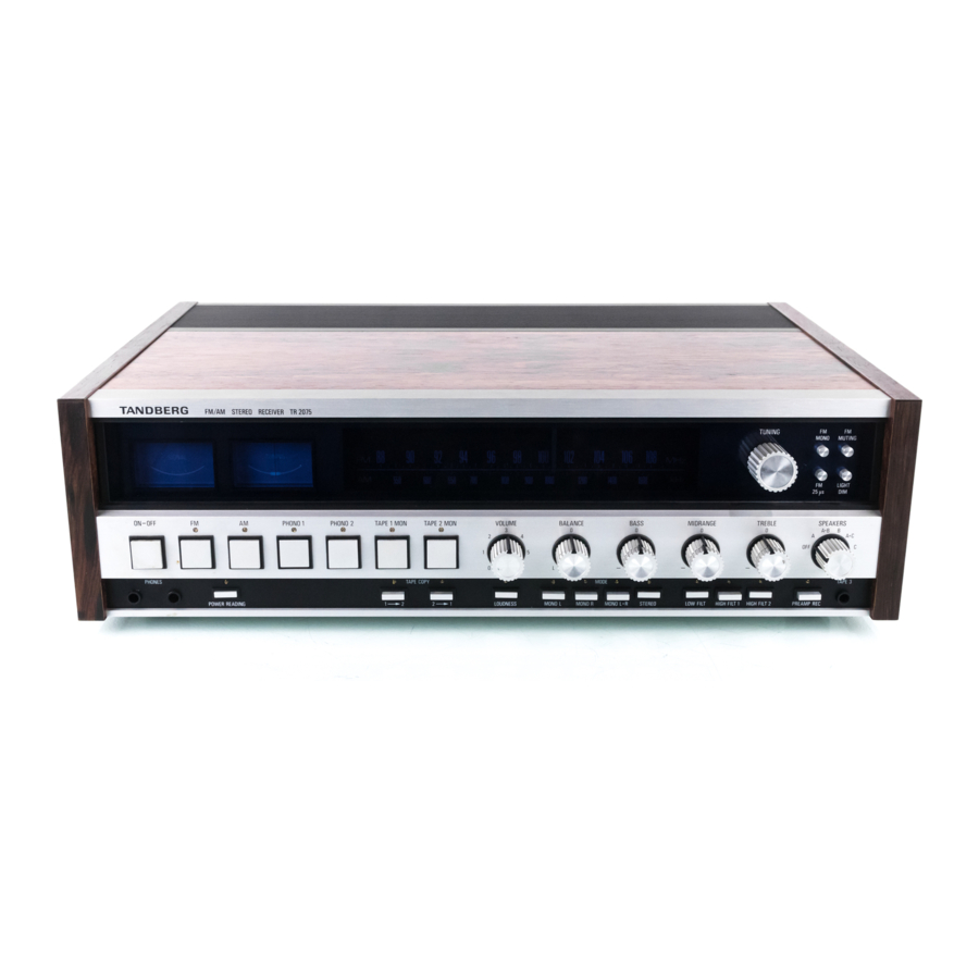
Summary of Contents for TANDBERG TR-2075
-
Page 2: Table Of Contents
Contents: Power ON/OFF switch ....................Page 3 Extra power sockets ......................Page 3 Light dim........................... Page 3 FM Antennas ........................Page 4 Tuning on FM........................Page 6 AM Antennas........................Page 8 Grounding ........................Page 8 Tuning on AM ........................Page 9 Volume - Balance ...................... -
Page 3: Power On/Off Switch
Power ON/OFF switch Make sure that the receiver is marked with the correct a.c. voltage for your supply. Switch the receiver on by depressing the ON/OFF-button. Another push on the button will release it and switch the receiver off. This button also controls the power to one of the extra power socket, marked SWITCHED, at the hack of the receiver (more details below). -
Page 4: Fm Antennas
FM Antennas What type of antenna do you need? Your need for a good antenna will depend on the receiving conditions where you live; the further you are away from the transmitter and the more obstacles (hills and tall buildings for example) between you and the transmitter, the greater will he your need for a good antenna. - Page 5 A simple folded dipole antenna A simple folded dipole for connection to the balanced input can be easily made from flat twin-lead with an impedance of 240 to 300 ohms, A 135 cm (53") piece of antenna lead should be used for the loop. Strip off approximately 1 cm (1/2'') of insulation at each end and solder as shown.
-
Page 6: Tuning On Fm
Tuning on FM Select FM reception by depressing the FM button. The red light over the button will light telling you that the receiver is in the FM mode. Use the large knob on the right side of the scale to tune in the required station. - Page 7 * The name Dolby is a registered trade mark of Dolby Laboratories Inc. ** FCC stands for Federal Communications Commission, the USA broadcasting standards organization. ***If you are using a Tandberg Tape Recorder with Dolby, set the Dolby knob of the recorder to DOLBY FM.
-
Page 8: Am Antennas
AM Antennas Ferrite-rod For operation in the broadcast band this receiver is equipped with a moveable ferrite-rod antenna. This antenna is intended for local reception where the signal strength is normally fairly high, but it can under favorable receiving conditions also pick up more remote stations efficiently. -
Page 9: Tuning On Am
Tuning on AM Select AM reception by depressing the AM button. The red light over the button will light telling you that the receiver is in the AM mode. Use the large tuning knob on the right side of the scale to tune in the required station. Tune for maximum deflection on the SIGNAL meter. -
Page 10: Stereo-Mono Switching
Stereo-mono switching Stereo-mono switching in the audio amplifiers may be performed for radio, disc, or tape programs by means of the STEREO, MONO L, MONO R, and MONO L+R mode buttons. STEREO button depressed - the two channels are separated for stereo reproduction. -
Page 11: Filters
Filters LOW FILT Rumble from a record player, acoustic feedback between speakers and a pick-up, or excessive bass resonance in a speaker or a room can all be controlled by means of the LOW FILT. The graph shows the effect of the control (-12 dB/octave). -
Page 12: Headphones
Headphones Stereo headphones can he connected to the 3-pole jacks marked PHONES on the left side of the front panel and the program level can be adjusted by the VOLUME and BALANCE controls. Two people can listen at the same time if two sets of headphones are plugged in and you can avoid disturbing other people in the room by switching the knob SPEAKERS to OFF. -
Page 13: Loudspeakers
A good all-round type of loudspeaker which is reliable in design, manufacture, and use is the totally enclosed infinite baffle type. Tandberg produce a full range of this type of loudspeaker. Ask your dealer for details. -
Page 14: Room Acoustics
Combinations of A, B, and C Each stereo channel has three sets of output terminals, A, B, and C. One way of using these outputs is to group two (A+B or A+C) speakers together for each stereo channel. If the speakers for each channel are separated by about three feet this will give a broader front to the stereo effect. -
Page 15: Speaker Selector
4. Arrange the speakers so that the distance between them is about 2/3 the distance to the listener. Too little distance between the speakers is better than too much. 5. When listening to a mono speech program switch over to one speaker by using the BALANCE control Speaker selector The speaker selector switch marked SPEAKERS has six... -
Page 16: Listening To Records
Listening to records Input sensitivity At the back of the receiver there are two sets of phono and DIN input sockets (marked PHONO 1 and PHONO 2) for When switching from one program source to another the output two transcription units or two record players, Each input has should not change. -
Page 17: Playback From Tape Recorders (Tape 1 And Tape 2)
Playback from tape recorders (TAPE 1, TAPE 2 and TAPE 3) At the back of the receiver there are two sets of phono and Input sensitivity DIN input, sockets (marked TAPE 1 and TAPE 2) for two tape recorders. Two reel-to-reel machines or two cassette The sensitivity of TAPE 1 input and TAPE 2 input can be machines or one of each type can be connected. -
Page 18: Recording From The Receiver
Recording from the receiver Connect one or two tape recorders to TAPE 1 input and/or Tapes with a high signal/noise ratio are known as "Low TAPE 2 input (or both) at the hack of the receiver. Use Noise/High Output'' tapes and they are gradually replacing phono or DIN plugs. -
Page 19: Recording From A Transcription Unit
Recording from a transcription unit Two tape recorders Connect a transcription unit (or record player) to the PHONO 1 socket and a tape recorder to the TAPE 1 socket A second tape recorder can be connected to the TAPE 2 socket at the hack of the receiver. -
Page 20: Copying Tape
Copying tape Two tape recorders involved TAPE MON. 1 button and the TAPE COPY 1 -> 2 button. If you now start all the machines, you will copy from TAPE 1 to a) Copying from TAPE 1 to TAPE 2 or vice versa. TAPE 2 &... -
Page 21: Recording On A Third Tape Recorder With Or Without Audio Controls
Recording on a third tape recorder with or without audio controls controls will be active as shown in the diagram below. If you want to record on a third tape recorder with or without the effect of the audio controls, connect the Although the source test can be carried out from the tape recorder by means of a 3-pole jack plug to the receiver, the tape test can only be carried out from the... -
Page 22: Monitoring During Recording
Monitoring during recording If the tape recorder has separate heads for record and playback, the program can he monitored at the same time as the recording is being made. Two types of monitoring are possible, one is the source test (A-test), the other is the tape test (B-test). -
Page 23: Simultaneous Recording Of A Radio/Transcription Program And Playback Of Another Program From Tape
Simultaneous recording of a radio/transcription program and playback of another program from tape jack is played through the speakers. The radio/ transcription Recording of a radio/transcription program on a tape program can only be monitored on headphones connected to recorder connected to the TAPE I socket or the TAPE 2 the tape recorder(s). -
Page 24: Plugs
Plugs Record player (PHONO) DIN plug Signal from pick-up, left channel Signal from pick-up, The plugs are seen from the wiring side. Shield connected right channel to record player chassis Common lead The common lead and the shield must not be wired together. Tape recorder (TAPE 1 and TAPE 2) DIN plug From tape recorder output Tape recorder (TAPE 3) and...
Need help?
Do you have a question about the TR-2075 and is the answer not in the manual?
Questions and answers
Jak rozkręcić wzmacniacz do czyszczenia potencjometrów
The context provides some details on cleaning potentiometers but does not give step-by-step instructions for disassembling the Tandberg TR-2075 amplifier. However, based on the available information:
1. Desolder the potentiometer – If needed, remove the potentiometer from the circuit board by carefully desoldering it.
2. Clean the potentiometer – Use white spirit and a toothbrush to clean it thoroughly.
3. Check movement and resistance – Ensure smooth movement and proper resistance after cleaning.
For full disassembly instructions, additional information would be required.
This answer is automatically generated