
Related Manuals for PRESONUS MP20


Summary of Contents for PRESONUS MP20
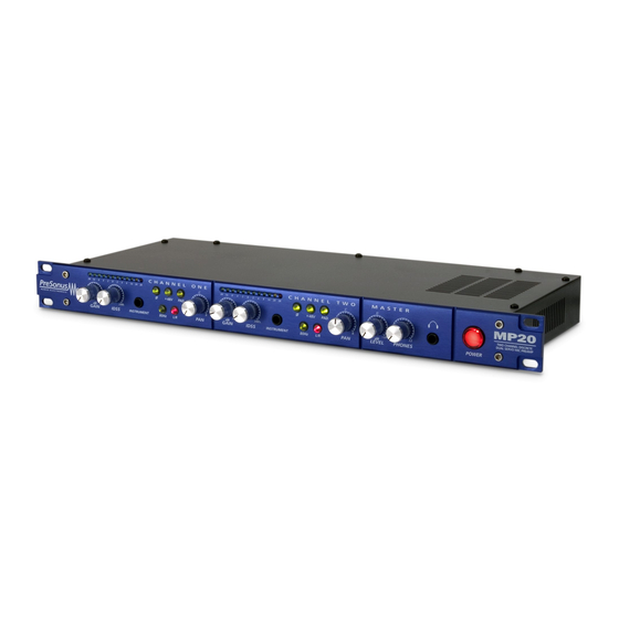
- Page 1 C H A N N E L M I C R O P H O N E P R E - A M P L I F I E R USERS MANUAL Version 1.1 1999,2001, PreSonus Audio Electronics, Incorporated. All rights reserved.
- Page 2 14 days of purchase. During the warranty period PreSonus shall, at its sole and absolute option, repair or replace, free of charge, any product that proves to be defective on inspection by PreSonus or its authorized service representative.
-
Page 3: Table Of Contents
TABLE OF CONT ENTS Overview Introduction Features Controls & Connections Front Panel Basic Layout Preamplifier Section Master Channel Back Panel Basic Layout Power Supply Operation Dynamic Microphones Phantom Powered Microphones Instrument Input Inserting Compressors, EQ’ s, etc. Using Return as Line In Aux Input –... -
Page 4: Overview
Microphone / Instrument Preamplifier with Stereo Bus. This pre-amp was designed using state of the art components to deliver crystal clear audio for an infinite period of time. We believe the MP20 to be an exceptional sounding unit and an exceptional value. Feel free to contact us at 1-800-750-0323 anytime for any reason whatsoever. -
Page 5: Features
OVERVIEW 1 . 2 F E A T U R E S The following is a summary of your MP20’ s features: FET, Class A Discrete Input Buffers. Each channel of your MP20 contains a Class A discrete input buffer followed by a dual servo gain stage. - Page 6 Mix Bus. The MP20 has a stereo summing bus for combining the input signals assigned to the bus using the L/R function switch on the front panel of the MP20. A pan knob allows the placement of the selected signal anywhere in the stereo array of the stereo summing bus out-going signal (i.e.- left;...
- Page 7 High Gain Headphone Jack Inserting stereo headphones into the jack on the front panel of the MP20 enables the user to monitor the signals assigned to the Stereo bus. Ample power has been provided to allow the operator to...
-
Page 8: Controls & Connections
Notice that the front panel is divided into two identical Preamplifier sections - Channel One and Channel Two - plus a Master section. Channel One and Channel Two are the two microphone preamplifier channels of the MP20. Both preamp channels contain: 80 Hz Filter... -
Page 9: Preamplifier Section
IDSS Control selects the amount of boost (0% to 100%) applied to the even harmonic series of the signal being amplified by a channel of the MP20. The effect of manipulating the harmonic distortion is of increasing or decreasing the apparent “... - Page 10 -20 dB Pad provides -20 decibels of attenuation with the push of a button. This is a very useful feature for rapidly reducing the level coming into the MP20 and thus preventing the input signal from over-modulating (distorting) the input.
-
Page 11: Master Channel
CONTROLS & CONNECTIO NS 12dB thus delivering a total gain possibility of 72dB. INSTRUMENT. This 1/4 inch input is provided so the MP20 can be used to boost low level instrument signals such as those typically encountered with electric bass and guitar. This feature is commonly referred to as a DI. This input allows pick-ups of electric and acoustic instruments to resonate at full frequency. -
Page 12: Back Panel Basic Layout
Combo jack is disconnected. High RING SLEEVE Cable Wiring Diagram for Balanced Send / Return Jacks Send Jack on the back panel of the MP20 routes the signal being processed by the channel to outboard devices or to recording media. -
Page 13: Power Supply
MP20 accepts a standard IEC cord like those found on most computers and professional recorders. Your MP20 has been designed to operate at the proper voltage for the country where you purchased your unit. Make sure that the power requirement of your unit matches the voltage of the country where the unit will be used. -
Page 14: Operation
3 . 4 I N S E R T I N G C O M P R E S S O R S , E Q ’S , E T C . Each channel of the MP20 features a send jack and a return jack. This feature allows the use of external processors such as compression and equalization devices. -
Page 15: Using Return As Line In
OPERATION 3 . 5 U S I N G R E T U R N A S L I N E I N The return jacks on each channel can be used to insert external audio devices such as tape machine outputs, DAT machine outputs, etc. This then makes the audio device available to the mix bus for mixing in with microphones or instruments. -
Page 16: Technical
Main Connection EIC receptacle Size 1U Rack 19” X 1.75” X 7” Weight 7 lbs. As a commitment to constant improvement, PreSonus, Inc. reserves the right to change any specification stated herein at any time in the future without notification. - Page 17 OPERATION...
Need help?
Do you have a question about the MP20 and is the answer not in the manual?
Questions and answers