Table of Contents
Advertisement
Advertisement
Table of Contents

Related Manuals for Alesis Matica 500


Summary of Contents for Alesis Matica 500
- Page 1 ALESIS Matica 500/900 Reference Manual...
-
Page 2: Table Of Contents
1: Introduction ... 3 About Alesis Maticaª Amplifiers ...3 Why Another Power Amplifier? ...4 2: Installation ... 5 Unpacking and Inspection...5 Physical Installation...5 Electrical Installation...6 Audio Installation: Input Wiring ...7 Audio Installation: Output Wiring ...8 System Setup and Testing ...10 3: Amplifier Operation... - Page 3 Matica 500/900 Reference Manual...
-
Page 4: 1: Introduction
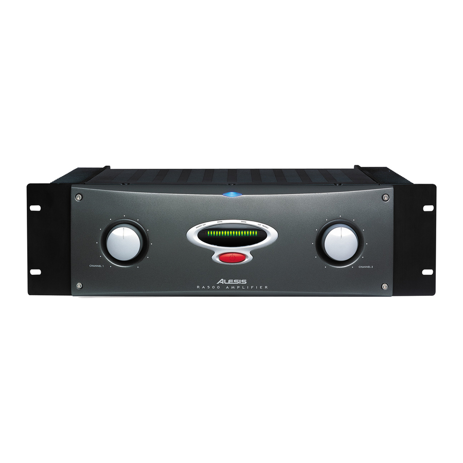
CLIP Figure 1: Amplifier front panel controls. About Alesis Maticaª Amplifiers Thank you for purchasing an Alesis Matica power amplifier, one of the most advanced and highest value amplifiers available. Your Alesis High Speed, Wide Bandwidth amplifier provides extremely accurate... -
Page 5: Why Another Power Amplifier
And yet, the primary purpose of any audio amplifier is reproducing sound with as high quality as possible. The new Alesis amplifiers meet the stringent requirements of both fixed and touring sound reinforcement, but they do not sacrifice sonic excellence to achieve their professional credentials. - Page 6 Introduction of recent developments in electronic componentry, and innovative design concepts make the Alesis power amplifiers ideal for any professional application. Matica 500/900 Reference Manual...
-
Page 7: Unpacking And Inspection
You as the consignee must make any shipping claims; neither your dealer nor Alesis can do this for you. If the amplifier was not shipped to you, i.e. you picked it up from your dealer, contact the dealer as soon as possible for assistance. -
Page 8: Electrical Installation
Matica amplifiers or any associated equipment with improper AC wiring. Note: Alesis amplifiers are pre-wired at the factory for the line voltage in the country where the amplifier is intended for sale and are supplied with appropriate line cords. -
Page 9: Audio Installation: Input Wiring
Warning: Be sure that the AC power is off prior to connecting or disconnecting any signal wiring. The input circuits of the Alesis amplifiers are electronically balanced. They may be fed from either symmetrical (ÒbalancedÓ) or unbalanced sources. There are two combination XLR/1/4Ó... -
Page 10: Audio Installation: Output Wiring
All input wiring should be done with shielded cable. To use an unbalanced source with an Alesis amplifier, connect the High (+) signal wire as shown in Table 1 and connect the shield wire to both the Low (Ð) and Audio Ground input connections. See Figure 4 and 6. - Page 11 Alesis amplifiers will not be damaged by excessively low output load impedances, but they will not be able to provide full output power and their protection circuits may automatically cut off their outputs until the low load condition is removed.
- Page 12 Channel A and B "hot" connections respectively. Next, the audio input to the amplifier must be from a balanced source. Wire the A Channel balanced input wiring with normal polarity but wire the B Channel's input with the Polarity inverted. Matica 500/900 Reference Manual...
-
Page 13: System Setup And Testing
Setting the system gain is fairly straightforward, but if it is not properly adjusted, the systemÕs distortion and noise characteristics may be less than optimum. The input sensitivity of the Alesis amplifiers is 0.775Êvolts (0ÊdBu) for rated output with the amplifier gain controls at maximum. If the signal at the amplifier input is higher than this, the input gain controls must be turned down to avoid amplifier clipping. - Page 14 Installations Matica 500/900 Reference Manual...
-
Page 15: 3: Amplifier Operation
These relays also disconnect the load very quickly when power is removed from the amplifiers, thus minimizing the chance that turn-off transients originating elsewhere in the system will be sent to the speakers. HAPTER PERATIONS Matica 500/900 Reference Manual... - Page 16 Installations Matica 500/900 Reference Manual...
-
Page 17: 4: In Case Of Trouble
¥Is the signal source working correctly? ¥Is the wiring to the amplifier input properly connected at both ends? ¥Have the gain controls of the signal source or the amplifier been moved since the system was set up? Matica 500/900 Reference Manual... - Page 18 Thin or Muffled Sound Audio Cuts In and Out Channel B Shows Heavy Clipping, Channel A is OK. Matica 500/900 Reference Manual ¥Is the signal source working correctly? ¥Are the systemÕs electrical and audio ground connections proper? ¥Are there any noise-producing sources on the AC mains circuit, such as light dimmers, motors, etc.? If so, it...
-
Page 19: 5: Reference
Rocker style high inrush power switch, manually resettable circuit breaker, green LED power indicator, individual detented level controls and individual red LED clip indicators Matica 500/900 Reference Manual Bridged Bridged 500 W 650 W 900 W... - Page 20 3 1/2Ó x 19Ó (2U) panels Matica 500: 12 1/4Ó (311 mm) depth Matica 900: 16 1/8Ó (410 mm) depth Matica 500: 30 lb (13.6 kg) Matica 900: 48 lb (21.8 kg) 14 gauge black powder-coated steel construction with integral front and rear rack mounts.
Need help?
Do you have a question about the Matica 500 and is the answer not in the manual?
Questions and answers