Fishman ELLIPSE MATRIX BLEND Installation Manual
Hide thumbs
Also See for ELLIPSE MATRIX BLEND:
- Installation manual ,
- User manual (8 pages) ,
- Manual (4 pages)
Advertisement
Quick Links
Installation Guide
Ellipse™ Matrix Blend/Ellipse™ VT
Ellipse Matrix Blend and Ellipse VT systems are compatible with
many x-braced, round hole guitars with 3.875" to 4.125" diameter
soundholes.*
*May not fit Taylor NT guitars, some Larivee guitars or instruments with ladder bracing.
Read Me First!
Installing an Ellipse system in a guitar is a simple procedure, but we
recommend this job only if you are an experienced guitar repair technician.
Please read and understand all these instructions before you install the
Ellipse system.
The Ellipse control module is designed to fit in most flat top guitars, but we
cannot guarantee it will fit in all instruments. Before you begin installation,
remove the strings and pre-fit the control module in the soundhole. Proceed
with installation only if the control module lays flat inside the instrument
and does not protrude beyond edge of the soundhole.
If you have any questions or comments, please contact us via Service/
Support at www.fishman.com.
Requirements
Saddle Slot
Minimum saddle slot length:
2.775" (70.48mm)
Maximum E to E string spacing at saddle:
2.5" (63.5mm)
Ellipse Module
Minimum usable soundhole diameter:
3.875" (98 mm)
Maximum usable soundhole diameter:
4.125" (107 mm)
Maximum x-brace height at soundhole:
.312" (7.9 mm)
Parts List
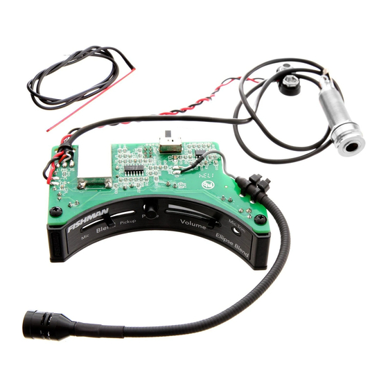
• Acoustic Matrix Pickup
• Ellipse control module
• 2 Adhesive backed wire clips
• Battery Clip (with screws)
Tools
• 3/32" (2.3 mm) drill bit
• 1/2" Reamer
• 1/2" Open end wrench
• 3/32" (2.3 mm) Slot head screwdriver
• #1 Phillips screwdriver
• Belt Sander (coarse grit)
• Fine grit sandpaper (#220 & #400 recommended)
• Alcohol wipes or rubbing alcohol and cotton swabs
Pickup Installation
Preliminary
The Acoustic Matrix pickup is handmade with delicate, acoustically transparent
materials. Handle the pickup element carefully during installation and please heed
these warnings:
• You may damage the pickup if you bend or twist it.
• If you tear or scratch the foil, the pickup will hum when plugged in.
• The pickup should fit easily in the saddle slot, without downward force. If it
binds in the sides or touches the ends of the slot, the pickup may hum, produce an
unbalanced sound or it may fail.
• Do not trim the pickup or it will hum when it is plugged in. Custom length
pickups are available through your Fishman dealer.
Fitting the Pickup
1. Remove the strings and the saddle.
2. To maintain the current action, remove material from the bottom of the saddle,
equal to the height of the pickup (.040" for narrow pickup, .050" for wide pickup).
Hold the saddle and the pickup side by side and carefully draw a pencil line across
the length of the saddle, at the height of the pickup.
3. Use a belt sander to remove saddle material, almost to the pencil line.
4. Sand the last bit of saddle material by hand until the bottom is even with the
pencil line. The bottom of the saddle must be absolutely flat. Place the saddle on a
straight edge and view it in front of a light source. If you can see light, the saddle is
not flat.
Note: The heat generated from a belt sander will almost always make a
synthetic saddle bow slightly on the bottom. When you sand a bowed saddle
by hand, do not hold it in the middle, or the saddle will behave like a spring
and you will never get the warp out. Instead, hold the saddle on the ends and
lightly sand it in one direction until it is flat.
5. Hold the pickup upside down in the slot and center it between the span of the
strings. Mark the corresponding wire hole location.
Note: The distance between the wire hole and adjacent string can be
no less than .100" (2.5 mm) for good pickup balance. You can use a
3/32" drill bit to gauge the minimum distance between the string and
the pickup wire.
No less than .100" (2.54mm)
6. Drill a 3/32" hole for the wire at the marked wire location in the bottom of the
saddle slot.
7. Clear all debris from the saddle slot. The bottom of the slot must present a
clean, flat surface for the pickup.
Note: If the bottom of the slot is uneven, bowed (belly up) or coated with
lacquer, it should be re-milled. For detailed instructions, go to the Service/
Support section at www.fishman.com and click on "Product Manuals
and Installation Guides", then download "Advanced Undersaddle Pickup
Installation."
8. Thread the wire into the hole and gently insert pickup into the saddle slot. The
pickup should fit easily in the saddle slot, without downward force.
9. Place the saddle in the slot and check the fit. As a rule of thumb, the saddle
should slide easily in and out of the slot, but it will not fall out when overturned. This
is called a "sliding fit."
•Saddle Too Tight
If the saddle binds in the slot and is difficult to remove, lightly sand it on one
side with fine grit sandpaper until you achieve a sliding fit.
•Saddle Too Loose
The saddle is too loose if you can wobble it front to back and it falls out of the
slot when overturned. When the saddle is too loose, the pickup signal and/or
balance may be degraded. You have two options:
A. Fit a new saddle (recommended).
B. Build up the thickness of the backside of the old saddle:
1/2 Slot Depth
Clear Tape
1. Drop the saddle in the slot and draw a line across the back of it (bridge
pin side), where the saddle meets the top of the bridge.
2. Remove the saddle and get some clear household adhesive tape.
3. Apply the tape across the back of the saddle. Position the top edge of the
tape halfway between the bottom of the saddle and the pencil line.
4. Trim off the excess tape and you are back in business!
Endpin Jack Installation
1. Remove the endpin and widen the hole with a 1/2" reamer.
2. Follow this sequence when you install the endpin jack:
1. Large hex nut
2. Large washer
3. Star washer
4. Guitar endblock
5. Small dress washer
6. Small dress nut
7. Strap nut
3. Adjust the large hex nut so the smaller threaded portion of the jack protrudes
outside the body at least 5/16" (7.9 mm), but not more than 11/32" (8.7 mm).
4. Fit the small dress washer and the small dress nut over the end of the jack and
then insert a 3/32" (2.3 mm) diameter Allen wrench or screwdriver shaft through
the small cross-drilled holes. Tighten the nut with a 1/2" open end wrench while
you hold the jack in place with the Allen wrench.
5. Thread the strap nut and tighten it.
Note: The end of the jack should protrude slightly over the
strap nut, so when a plug is inserted, it will snap securely
in place.
Battery Holder Installation
Mount the battery holder to a small block of hardwood or MDF with the supplied
screws. The dimensions for the block are 1.125" x .75" x .5" (28.6 mm x 19 mm
x 12.7 mm). Use the battery holder as a template to mark the hole locations on the
block. Drill pilot holes for the screws with a 3/32" (2.4 mm) bit. Once you fasten the
battery holder to the block, adhere it to the neck block with wood glue or a gap filling
cyanoacrylate adhesive such as Loctite
®
410.
Control Module Installation
Install the pickup in the bridge and fasten the pickup wire to the terminal block under
the metal shield on the control module. The signal wire goes to the "IN" side of the
block and the shield wire goes to the "GND" terminal. Screw down the wires with a
small flat-head screwdriver.
������
��������������
���������������������
��������������
���������
����������������
�����������
1. Test the area where you will mount the control module. Locate the module flush
with the edge of the soundhole, on the bass side. Center the module between the
transverse brace above the soundhole and the bass-side x-brace. If you view the
soundhole as a clock face (neck at twelve o'clock), position the phase switch at nine
o'clock.
����������������
�����
�������
2. Use 120 grit sandpaper to remove any excess lacquer or buffing compound from
the inside edge of the soundhole, then clean this surface with an alcohol wipe or a
cotton swab wetted with rubbing alcohol. Let the alcohol dry.
Note: At this point, you may fasten the preamp module in the soundhole and
you can expect an adequate and reliable bond. But note that you will achieve
the strongest and most effective bond if you now apply a water-based primer/
sealer to the bare wood inside the soundhole. Let the primer/sealer dry before
continuing.
Peel back the release film on the bottom of the mount and affix the module to the
underside of the soundhole. Apply even, steady pressure to the module to set the
adhesive. The adhesive gains maximum hold after 24 hours.
3. You may separate the control module from the magnetic base for better access
inside the guitar. The module is held by two powerful magnets, located on the right
and left sides of the unit. To separate the module, locate the tab on the right edge
of the unit and push it down, toward the back of the instrument. Once you feel
the magnet let go, swing the module towards the soundhole, then separate the left
magnet.
www.fishman.com
Over —>
Advertisement

Related Manuals for Fishman ELLIPSE MATRIX BLEND


Summary of Contents for Fishman ELLIPSE MATRIX BLEND
- Page 1 1. Test the area where you will mount the control module. Locate the module flush B. Build up the thickness of the backside of the old saddle: pickups are available through your Fishman dealer. with the edge of the soundhole, on the bass side. Center the module between the transverse brace above the soundhole and the bass-side x-brace.
- Page 2 The saddle height and the relative position of the bridge pins determine the break angle. A new guitar with a tall saddle will usually have sufficient break angle, but Fishman Transducers, Inc. an instrument with a low saddle may require an increase. To raise the break angle, Mic Trim the string slots in the bridge can be “ramped”...