Midland P25 Operation Manual
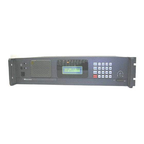
Base/repeater station
Hide thumbs
Also See for P25:
- Operation manual (84 pages) ,
- Service manual (77 pages) ,
- Operation manual (72 pages)

Related Manuals for Midland P25


Summary of Contents for Midland P25
- Page 1 Operations Manual for the P25 Base Tech III Base/Repeater Station January 2009 Version 5.1 680-090-2042 www.midlandradio.com...
- Page 2 Introduction We thank you for choosing the Midland P25 Base Tech III Base/Repeater Station to meet your communication needs. Properly used, this product will give you many years of reliable service. To get the most out of your purchase, be sure to carefully read this manual before operating the radio.
-
Page 3: Table Of Contents
1. LCD Display 2. LED Display 3. Key Controls 4. Programming 5. Control Knob 6. Channel Selection 7. P25 Calling Selection 8. P25 PTT Mode 9. P25 Conventional Messages 10. P25 Squelch Adjustment 11. Talk Group ID Alias 12. Key lock 13. -
Page 4: Lcd Display
C001 TAC 2 MD⌧N 2. LED DISPLAY The Midland Base Tech III has 5 LED's From left to right; DIGI= The LED is on when receiving a digital signal REP= The LED is on when in repeat mode. (The BASE TECH III can be programmed for, SIMPLEX -SEMIDUPLEX - DUPLEX- REPEATER on a per channel basis.) -
Page 5: Key Controls
*= Cancel channel number, individual number #= Ending channel number, individual number CH= Channel number entry, depress CH, then 0-9 for channels F (Scan) = P25 Conventional Control Messages (SBC) MON= monitor ON or OFF Rotary knob: Volume, Squelch, Back Light Dimmer and Timer 3.2 Key entry following SHIFT key... -
Page 6: Programming
4. PROGRAMMING The Midland Base Tech III must be programmed with Windows 2000, XP or Vista operating system. The 91-1480CD software and 91-1303B programming cable are required to program the radio and are available through your Midland dealer or LMR Sales Department. -
Page 7: Channel Selection
Figure 6 6. CHANNEL SELECTION The Midland Base Tech III has capability of up to 500 channels. Press CH, and then enter the channel number. Example-1 CH-8; Press CH + 0 + 0 + 8 or CH +8 + # Example-2 CH-500;... -
Page 8: P25 Calling Selection
7. P-25 CALLING SELECTION (Digital Base Mode Only) Press and release A repeatedly to scroll through the menu Radio displays GPC 00001= Group 1 Call, GPC everygroup= All Call, IDC--------- = Individual Call Figure-7 Shows Talk Group Identification (TGID), Group 1 Call Figure-8 shows an All Call (everygroup), to everygroup on the same NAC Figure-9 Shows an Individual Call, to and individual unit ID on the same NAC. -
Page 9: P25 Ptt Mode
7.1 INDIVIDUAL CALL ENTRY (Digital Base Mode Only) Press and release A repeatedly until IDC----- is displayed. Press B, and enter the numerical Unit ID. To deleted a digit, Press the star ( * ) key Press B or # to complete entry. Figure-10 shows entry start, when B is pressed Figure-11 shows completed entry, 1 + 2 + 3 + 4 + 5 + B C001... -
Page 10: P25 Conventional Messages
9. P25 CONVENTIONAL CONTROL SIGNALLING (SBC) (Digital Base Mode Only) Please note: SBC functions are selectable in the Programming Software. The Base Tech III has been developed to work with any P25 radio under the TIA specifications. However not all subscriber radios have the capability of these functions. - Page 11 9.2 CALL ALERT- To send a Call Alert, Press F then Press A or B until the selection is displayed, then enter the target ID of the radio to alert and Press #. If the target radio has received the Call Alert the display should show “ACK” (acknowledgement). Figure 14 displays a Call Alert ACK Call Alert To: 366...
- Page 12 9.4 RADIO INHIBIT- This function is used to disable a subscriber unit (Mobile or Portable). The subscriber unit cannot be turned on at all until an Uninhibit Command is sent. The password must match the password entered in the BTIII program for inhibit to occur. To Inhibit a radio, Press F then Press A or B until the selection is displayed then enter the target radio’s ID.
- Page 13 9.6 STATUS UPDATE- Used to send user status. The status numbers relates to an actual message list. Indicates the User status (0-255) and Unit status (0-255). To send a Status Update, Press F then Press A or B until the selection is displayed and enter the target radio ID.
- Page 14 9.9 PREDEFINED MESSAGES- Is used to send a predefined system message. To send a Predefined Message, Press F then Press A or B until the selection is displayed, then enter the target radio ID, Press D and enter a message number and Press #.
- Page 15 Press F then Press A or B until the selection is displayed, then enter the complete telephone number including country and area code. (max. 16 digits), then Press #. Figure 22 shows the Midland Radio Corporation telephone number. Telephone To:18162418500 MD⌧N...
-
Page 16: P25 Squelch Adjustment
10. P-25 SQUELCH ADJUSTMENT Press SHIFT + MON to choose the P-25 squelch mode. Normal SQL= If NAC is the same, the receiver will unmute Selective SQL= If NAC and GROUP is the same, the receiver will unmute Figure-24 Shows Normal SQ Figure-25 Shows Selective SQ C001 TAC 2... -
Page 17: Key Lock
12. KEY-LOCK Press SHIFT+8 to enable and disable the Key-lock. This symbol shows on the LCD. Key-Lock and Key-Unlock icon is displayed for 2 seconds and then reverts to show the TGID. The PTT, MON and SHIFT key are not locked If PTT, MON and SHIFT needs to be locked, select DISABLE in the programming software. -
Page 18: Manual Cwid Start/Stop
Press SHIFT+ HOLD B for 2 seconds (CWID must be enabled in programming to use these functions). Figure 29 shows CWID Sending Figure 30 shows CWID function stop Figure 31 shows CWID function start CWID sending Code: MIDLAND C001 TAC 2 MD⌧N Figure 29 C001 TAC 2 MD⌧N... -
Page 19: Analog Channel Data
15. ANALOG CHANNEL DATA Press SHIFT+7 to scroll through the data. 7 must be depressed to scroll. 1) Rx width (narrow/wide/4kHz) 2) TX width (narrow/wide/4KHz) 3) Base mode (Simplex/Semi-duplex/Duplex/Repeater) 4) Rx CTCSS/DCS, CTCSS and DCS are used in Rx 5) TX CTCSS/DCS, CTCSS and DCS are used in TX 6) TX RX Modulation type either PM or FM (PM is the default) (The INFORMATION DISPLAY selection in the 91-1480CD MISCELLANOUS MENU must be set to ENABLE to display this information.) -
Page 20: Bar Graph/Channel Display
17. BAR GRAPH/CHANNEL DISPLAY Press SHIFT + CH to eliminate the channel name/bar graph and display the frequencies for TX and RX. Press SHIFT + CH to toggle back. Figure-35 Displays the frequencies instead of channel name. The 1 and 2 character on line 1 indicates Receive Channel The 3 character indicates Wide band... -
Page 21: Changing Tx Power
GPC 00001 Figure 37 20. CALLER ID In Simplex mode the Midland Base Tech III display indicates the source Unit ID or Individual ID. Figure-38 Displays the source ID as 00000366 in group call mode. Figure-39 Displays the source ID in Individual Call mode. -
Page 22: Emergency Call Reception
21. EMERGENCY CALL RECEPTION The 4th line of the LCD shows the Emergency ALM when an emergency call is received. The LCD back light flashes and the audible tone heard from the speaker can be increased or decreased with the volume control. Figure-39 below displays the Emergency Caller's ID 00000366. -
Page 23: Base Mode
23. BASE MODE 23.1 ANALOG If the received CTCSS/DCS matches the programmed CTCSS/DCS, the radio’s receiver will open. The MON key may be pressed to bypass any tone signaling. 23.2 DIGITAL Matching NAC (Network Access Code); If the programmed NAC/TGID matches the received NAC/TGID, the receiver will open. -
Page 24: P25 Test Mode
- Sends the Standard Tone Test Pattern in TX mode. - Indicates BER (Bit Error Rate) in RX mode. Figure-42 Displays that the radio is in the “P25 Test Mode” and “Test Pattern” Figure-43 Displays Symbol Rate Figure-44 Displays Low Deviation... - Page 25 <P25 Test Mode> Low Deviation C001 MD⌧N Figure 44 <P25 Test Mode> C4FM Modulation C001 MD⌧N Figure 45 <P25 Test Mode> Tone Test C001 MD⌧N Figure 46 <P25 Test Mode> Tone Test C001 MD⌧N Error Rate Figure 47 www.midlandradio.com Version 5.1...
-
Page 26: Adjustment Mode
26. ADJUSTMENT MODES While Grounding TP-2 on the analog logic board, switch the radio on. See the Midland Base Tech III Service Manual for the TP-2 location) Press # to change selections. Press A (Up) and B (Down) to adjust the level. - Page 27 RXWH <Adjust> RX 0dbm Out C001 25 / 31 Figure 48 RXWH <Adjust> FX828 MOD1 C001 0 / 31 Figure 49 RXWH <Adjust> DIGITAL DEVI C001 27 / 31 Figure 50 RXWS <Adjust> ANALOG DEVI C001 19 / 31 Figure 51 RXWH <Adjust>...
-
Page 28: Key Test
27. KEY TEST Press and Hold C, switch on the radio. Then depress any key to test. Figure-53 shows initial display Figure-54 shows CH key depressed. Figure-55 shows rotary switch turn clockwise Figure-56 shows rotary switch turn counter-clockwise If no key is pressed for 5 seconds, the radio reboots to normal operation. <Key Test>... -
Page 29: Displaying Firmware Version
28. DISPLAYING THE FIRWARE VERSIONS Both the radio and DSP firmware versions are indicated on the LCD after the radio switches on for 2 seconds, unless a “Starting Message” has been programmed. Figure-57 Displays Radio and DSP Firmware versions <71BSV200A710> DSP V109 <... -
Page 30: Displaying Program Software Ver
Figure 60 31. DATA CHECK The Midland Base Tech III has a self diagnostic function. All data in the EEROM is checked every time the radio is switched on. If the data is not properly stored, the radio automatically turns to programming mode... -
Page 31: Error Messages
32. ERROR MESSAGES If there is a problem with the RX PLL, TX PLL or PA, then the ALM LED flashes on and indicates which section has the issue. Figure-49 displays a RX PLL error, Note this may be displayed in REM mode if the remote channel lines are open or a channel is selected remotely that is not programmed. -
Page 32: Dsp Error Detection
35. DSP ERROR DETECTION When there is a problem with the DSP, the following message may be shown on the display. Please check that the DSP board is installed correctly, and the correct firmware version is displayed at startup. Figure-65 shows DSP failure Figure-66 shows DSP not ready Figure-67 shows DSP serial error C001... -
Page 33: Option Port Pinout
36. Option Port Pinout 25 pin D-sub connector for remote control is provided on the rear panel of Base Tech III. The functions of each pin are as follows: Name Description Levels Comments LSB external binary 0-+3.3VDC 0000 is channel 1 channel selection External binary channel 0-+3.3VDC... - Page 34 5900 PARRETTA DRIVE• KANSAS CITY • MISSOURI • 64120 PHONE: (816) 241-8500 • FAX: (816) 241-5713 www.midlandradio.com...
Need help?
Do you have a question about the P25 and is the answer not in the manual?
Questions and answers