Advertisement
- 1 INSTRUCTION FOR THE INSTALLER
- 2 INSTRUCTIONS FOR THE USER
-
3
TROUBLESHOOTING
- 3.1 Machine does not operate
- 3.2 Disposer, Press or Pump not operating
- 3.3 Disposer Not Cutting
- 3.4 Disposer Noisy Operation
- 3.5 Machine Leaking
- 3.6 Sink overfilling with Water
- 3.7 Disposer is working no waste coming from Press
- 3.8 Press Liquid coming from waste Chute
- 3.9 Press not processing material
- 3.10 Excessive vibration from machine
- 3.11 Shower system not working
- 3.12 Machine does not stop after Stop Button is pressed
- 4 GENERAL RECOMMENDATIONS
- 5 Documents / Resources
INSTRUCTION FOR THE INSTALLER
STATUTORY NOTICE
THIS EQUIPMENT HAS TO BE INSTALLED WITH ADEQUATE BACKFLOW PROTECTION THAT COMPLIES WITH FEDERAL, STATE OR LOCAL CODES HAVING JURISTICTION
GENERAL INSTALLATION INSTRUCTIONS
IMPORTANT SAFETY INSTRUCTIONS
To ensure the correct safe and reliable operation of the COMPACT it is important that the installation is carried out by qualified Electrician and Plumber.
It is recommended that all persons who are to work with the machine receive thorough instruction in the safety and hygiene regulations.
INSTALLATION LOCATION REQUIREMENTS
The COMPACT Organic Waste Processing unit requires a floor area of 750 x 962 mm. There must be sufficient space in front of the unit for removal of the waste container and for cleaning of the discharge chute.
For reasons of hygiene, the machine should be sited so that it is separated from the food preparation area. It is recommended that the installation site be selected so as to allow easy and thorough cleaning of the outside of unit following operation. A floor waste outlet close to the machine and a water-repellent wall coating are convenient.
For electrical connection of the unit you will need a 380/400v 3ph 5 wire 50/60Hz (currant rating 16 Amps) supply. Ensure that a qualified electrician installs the connection point.
Both HOT and COLD water supplies are required as well as access to an outlet for waste water, floor drain.
IMPORTANT SAFETY INSTRUCTIONS
In order to prevent injury or damage to the Unit always handling and lifting aids when moving heavy equipment, if in doubt consult your Manager or Safety Officer.
IMPORTANT HEALTH & SAFETY NOTICE
The appliance must always be fully disconnected from the electric power supply before any necessary repair or maintenance work is carried out. It is essential that the power supply cable and connection socket provided in the premises are installed and checked by an authorised electrician.
INSTALLATION
Remove lower front panel by removing retaining bolts. Store panel carefully to prevent damage or loss of fasteners.

IMPORTANT SAFETY INSTRUCTION
SERVICE MODE OPERATION
IN ORDER TO OPERATE THE MACHINE WHEN IT IS NECESSARY TO OVERRIDE SAFETY SWITCHES THE MACHINE MUST BE PUT INTO SERVICE MODE.
TO DO THIS PRESS AND HOLD THE "STOP BUTTON" THEN PRESS THE "START BUTTON" 10 TIMES AT ONE SECOND INERVALS.
THE START/STOP BUTTON WARNING LAMP WILL FLASH CONTINUALLY TO CONFIRM MODE IS ACTIVE.
THIS WILL ALLOW THE MACHINE TO BE OPERATED WITH THE LID/CHUTE OPEN.

PRESS THE EMERGENCY STOP BUTTON TO RETURN THE MACHINE TO NORMAL MODE.
THIS MODE MUST NOT BE USED DURING NORMAL OPERATION!
WATER SUPPLY
The COMPACT unit is connected to both cold and hot water. The ¾-inch wide connections are located at the rear of the machine. Only pressure-resistant connecting tubes must be used. It is essential to ensure that the connection of the two water supplies to the appliance is not reversed, since otherwise processing of organic wastes, which contain fats or starch, will result in the formation of deposits in the wastewater pipe. The recommended water connections are soft (plastic) fittings, use of metal connectors will damage the machine ports. It is recommended that the water connection is carried out by a qualified person.
Cold and hot water connections must not be reversed!
The water connections are marked "H" Hot & "C" Cold.

WASTE/DRAIN CONNECTION
Unscrew electrical box retaining bracket from main machine frame by removal of fasteners, it is not necessary to remove Electrical Control Box from Bracket. Lift out Electrical Control Box and Bracket, stand assembly to side of machine do not strain cables. Take care not to lose fasteners.
The connection to the waste water system is un-pressurized and easy to install using standard 50mm pipe and fittings supplied. The waste pipe can be routed in a number of directions out of the unit, straight down (though not recommended unless the machine is located directly over a drain) or to the side/rear of the unit. Breakout points are precut in the side and rear panels to accommodate routing of the waste pipe.

DIRECTION OF ROTATION
When installing the unit, you must ensure that you maintain the specified direction of rotation of the Motors when viewed from the front of the machine.


ENSURE THAT THE UNIT IS INSTALLED WITH THE CORRECT DIRECTION OF ROTATION WHEN VIEWED FROM THE FRONT OF THE UNIT, LOOKING ON TO THE MOTOR FAN.
If necessary, change the phases in the power supply. Following connection to the electric power supply, check for correct direction of rotation as follows. Switch the unit to 'ON' for 2 seconds and check the direction of rotation of the Disposer motor, counter cockwise when viewed from the front of the unit. If this is the case, the polarity of the unit is correct. Incorrect polarity will result in damage to the appliance, and invalidate the warranty.
Structural alterations in your power supply network can result in interchanging of phases. This means that following any work on your internal supply network you must ensure that the COMPACT motors rotate in the correct direction.
GROUNDING INSTRUCTIONS
The COMPACT must be grounded. In the event of malfunction or breakdown, grounding provides a path of least resistance for electric current to reduce the risk of electric shock. This COMPACT is equipped with a cord having an equipment-grounding conductor and a grounding plug. The plug must be plugged into an appropriate outlet that is properly installed and grounded in accordance with all local codes and ordinances. A qualified electrician must be consulted if there is any doubt as to whether an outlet box is properly grounded.

Improper connection of the equipment-grounding conductor can result in a risk of electric shock. The conductor with insulation having an outer surface that is green with or without yellow stripes is the equipment-grounding conductor. If repair or replacement of the cord or plug is necessary, do not connect the equipment-grounding conductor to a live terminal. Check with a qualified electrician or serviceman if the grounding instructions are not completely understood, or if in doubt as to whether the COMPACT is properly grounded. Do not modify the plug provided with the COMPACT if it will not fit the outlet, a proper outlet must be installed by a qualified electrician.
This COMPACT is for use on a circuit having a nominal rating more than 120 V and more than 15 A and is equipped with a specific electric cord and plug. No adapter should be used with this COMPACT. If the COMPACT must be reconnected for use on a different type of electric circuit, the reconnection must only be made by qualified service personnel; and after the reconnection, the COMPACT must comply with all local codes and ordinances.
POSITIONING AND ADJUSTMENT OF FEET
It is important that the COMPACT stands level, and stands firm to achieve this the feet must be adjusted.
- Using a pipe wrench (or similar) unscrew the tube visible above the feet, clockwise when viewed from above. This tube acts as a locking nut to set the foot once adjusted.

- By hand adjust the feet to level the machine, take care not to unscrew them too far and detach them from the machine frame.

- Once the machine is level retighten the outer tubes (counter clockwise when viewed from above), using a pipe wrench or similar, to fix the position of the feet.

- Ensure machine stands firm and does not rock, check with spirit level.


WATER FLOW ADJUSTMENT
To ensure that COMPACT processes material correctly, operates efficiently and does not overfill or splash, the water flow can be controlled for the sink and the Press.
Water Flow Adjustment - Press
Remove the Chute from the end of the Press. With water connected to Machine, press Start Button and check that water is not coming out of the Press exit. If water is found to be coming from exit adjust valve to reduce water flow

Water Flow Adjustment - Sink
When the machine is operated check the water flow in the Sink, water inlet ports are located at the front and rear of the sink. The flow should be a sufficient to wash organic waste to be processed into Disposer. If there is evidence of splashing from sink the water flow can be reduced by adjusting the valves located at the front of the sink.

MAINTENANCE
IMPORTANT SAFETY INSTRUCTIONS
MAINTENANCE OPERATIONS MUST ONLY BE CARRIED OUT BY APPROVED PERSONNEL ONLY
In order to prevent injury or damage to the Unit always handling and lifting aids when moving heavy equipment, if in doubt consult your Manager or Safety Officer.
When accessing sink ALWAYS lock Chute Lid in the open position.
INTRODUCTION
To assure long life and reliable service of the COMPACT it is important to ensure that routine maintenance tasks are carried out.
ROUTINE MAINTENANCE
YEARLY CHECKS – MAINTENANCE ENGINEER
- Isolate Power to the unit
- Pull machine from location
- Remove lower front panel.
- Check drive belts to check for wear. Remove inspection panel located at the rear of the unit removing retaining bolts. Check belt tension, grip each belt in turn halfway between pulley wheels, tension is correct when belt can be twisted through 90°, also check the teeth on the belt for wear. Always replace belts as a pair.

- Disassemble outlet chute, above bin, and thoroughly clean internal surfaces. Also clean exit port of Press.
- Isolate water supplies (HOT & COLD)
- Disconnect the water supply pipes to allow access to water inlet solenoid valves. Clean water inlet filters, remove water inlet pipes to access plastic inlet filters check direction of filter before removal(see photo). Pull each filter out using pliers and clean any debris from mesh, and replace as removed, crown outwards.
(NOTE: When the machine is installed in a newly constructed building it is recommended that the water inlet filters are inspected and cleaned weekly).
![]()
- Re-activate electrical power
- Run Machine check for leaks; use"Service Mode Operation" when necessary.
- Refit all external panels and replace machine in its location.


INSTRUCTIONS FOR THE USER
GENERAL INFORMATION ON ORGANIC FOOD WASTE PROCESSING
The COMPACT Organic Waste Food Macerator and Water Separator Unit has been designed for simple use and operation. The principle function of the COMPACT is to reduce surplus food / organic waste into a manageable volume in a cost effective manner.
ALL YOU CAN EAT, YOU CAN TREAT!
The COMPACT can be used to process any organic waste, whatever can be eaten can be processed, in solid or liquid form. No packaging or other materials, including such things as bones, egg or animal shells must be put into the machine, processing of any such materials will invalidate the warranty.
MATERIALS SUITABLE FOR PROCESSING
The COMPACT/INTAKE will process the following kinds of food and organic waste (Cooked or UnCooked).
| ORGANIC MATERIAL | REMARKS |
| Simple Rule for Operators | IF YOU WOULD NORMALLY EAT THE PRODUCT IT CAN BE PROCESSED. |
| All Cooked / Uncooked Vegetable matter. Highly fibrous products such as corn on the cob - MAX PERCENTAGE ALLOWED: 30% of the mix | Highly fibrous products such as corn on the cob should be feed into the units mixed with normal vegetable matter in MODERATION. Should only highly fibrous products be processed the unit is likely to malfunction and block (highly fibrous product should if possible be disposed of in the normal manner i.e. Directly into the waste disposal skip/dumpster. |
| All store vegetable trimmings MAX PERCENTAGE ALLOWED: 80% of the mix | With vegetable trimmings care should be taken not to mix the trimmings with (wire ties / plastic ties / elastic bands/ plastic wrapping paper) etc.  Trimming knives should not be left in the waste; this will be a heath hazard and a danger to the operator and will damage the machine. |
| All Fruits Fruit with nuts / stones / kernels - MAX PERCENTAGE ALLOWED: 30% of the mix | Some large fruits such as watermelons will need to be cut into manageable sizes to feed into the unit. Fruit with nuts / stones / kernels can be feed into the unit 'IF MIXED' with other non-stone vegetables. |
MATERIALS CRITICAL FOR PROCESSING
| To reduce the risk of damage to the unit and personnel injury by materials that may be expelled by the COMPACT, STRICTLY FOLLOW THE BELOW INSTRUCTIONS! | |
| Bone MAX PERCENTAGE ALLOWED: 30% of the mix, ONLY IF they are cooked AND of chicken type. NO COW, NO PORK BONES ALLOWED) | Large / knuckle end bone must be avoided |
| Eggs Shell MAX PERCENTAGE ALLOWED: 10% of the mix | Egg shell is highly abrasive and will not breakdown early due to its structure. However, in moderation with other waste material egg shell can be disposed of via the unit |
| Fish Skin – Uncooked MAX PERCENTAGE ALLOWED: 20% of the mix | This product is not recommended to be processed in this unit. Fish skin tends to twist and become like rope and will not pass through the unit. |
| Mussels shells MAX PERCENTAGE ALLOWED: 5% of the mix | |
MATERIALS NOT ALLOWED AT ALL FOR PROCESSING
| China | Glass, tableware, Drinking cups |
| Metal | Bottle tops, metal tableware, aluminum cans and foil, trimming knifes, wire ties |
| Plastic | All plastic material, including plastic cups and packaging |
| Wooden Objects | Food packaging, wood generally |
| Cleaning Material | Cloth, mops, rope, cleaning liquid containers |
INTRODUCTION
| IMPORTANT SAFETY INSTRUCTIONS NEVER ATTEMPT TO OPERATE THE MACHINE IF:
|
Before starting the COMPACT ensure that you are thoroughly familiar with the controls of the machine and its operation.
Ensure that the machine is connected to the electric power, water and wastewater systems. Ensure that the Lid/Chute of the machine is closed.

CONTROL PANEL FOR COMPACT UNITS
OPERATING PROCEDURE
DAILY START UP
- Check any loose leads there are no leaks, and inlet chute and waste discharge chutes are free of obstacles or foreign matter.
- Ensure waste bin is empty, clean and in position.
- Pull out EMERGENCY STOP switch, wait 3 seconds to reset.
- Press Green START BUTTON and operate for one cycle without load, towards the end of the cycle (approximately 1 minute) open chute ensure that machine stops.
- The unit is now ready to process material.
- Press the Green START BUTTON to commence cycle.
- Feed material into the opening in the Lid/Chute at a steady rate taking care not to overfill the sink.
- The processing cycle will automatically stop after two minutes, if there is further material to process press the START BUTTON again to commence another cycle.
- If the Lid/Chute is opened to the sink the unit will stop automatically. To restart the unit, close the Lid/Chute and press the START BUTTON.
END OF SHIFT SHUT DOWN OF MACHINE
- Run machine through full cycle to clear any waste in process.
- Pour approximately 80cc of washing up liquid into sink and run machine through a further cycle
- Press and Hold Green START BUTTON to activate cleaning cycle
- Wash through sink using machine shower hose
- Wipe off external surfaces
- Empty and clean waste bin
- Clean general work area of any waste materials.
- Press EMERGENCY STOP button which will switch off all systems
- Clean machine waste outlet pipe internally
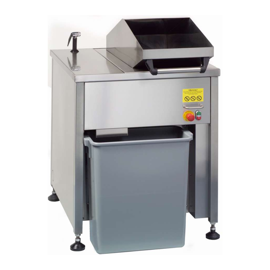
WASTE BIN (DISPOSAL OF ORGANIC WASTE)
The collection bin is located at the front of the COMPACT (note photograph below). Ensure that it is directly beneath the exit chute of the Press to prevent spilling of waste product. It is important that the waste bin is correctly positioned and NOT overfilled with waste.
")
Although the organic waste that you are processing will decrease in volume by up to 50/60%, the weight of that waste will NOT decrease. As a guide to this operation, the waste bin should only be filled up to half way i.e. 50% and should it be found that the bin is too heavy for one individual to lift for final disposal, in to the skip/dumpster assistance MUST be sought.
IMPORTANT SAFETY INSTRUCTIONS
PROCESSED WASTE IS HEAVY. DO NOT TO OVERFILL THE WASTE COLLECTION BIN
As an aid to the disposal of the waste and in the interest of hygiene a plastic bag can be inserted into the bin
(Part Ref: 1600/300g). This will help with the final disposal of the waste into a skip/dumpster; it is recommended that the neck of the plastic bag is sealed before disposal.
CLEANING & DAILY MAINTENANCE
INTRODUCTION
The COMPACT is self cleaning in operation however in the interests of Hygiene, a safe working environment and to ensure the continuing reliability of the COMPACT it is important that it and the surrounding work area are kept clean and tidy. It is critical that the recommendations for cleaning are followed, including the using only approved substances to aid degreasing as aggressive detergents will damage the machine's internal components.
When accessing Sink ALWAYS lock Chute Lid into open position

CLEANING THE UNIT
It is recommended that at the end of each shift or if the unit is to be shut down that it is cleaned manually.
Flushing through can be activated whilst running by holding the GREEN start button down.
Do not put any cleaning tools (brushes or rags) into the machine at any time. Wipe all external surfaces.
Use machine cleaning shower hose to wash the machine through this only operates whilst the machine is running and for a further 2 minutes after its operating cycle. If residue deposits are still visible, repeat the cleaning process.
Only use washing up liquid soap, suitable for dish washing, to clean the machine.
NEVER use abrasives strong detergents, pipe unblocking substances or bleach, as such products can cause damage to internal components within the unit. Use of such will invalidate the warranty.
DAILY MAINTENANCE (HYGIENE CHECK)
- Wipe machine's external surfaces
- Wash through with liquid soap suitable for dish washing
- Flush Machine through using machine's shower hose
- Empty Bin regularly, particularly at the end of a shift, and wash bin to remove residues.
- Clean waste outlet to waste receptacle.
- Open lid and check the Red service light is on and flashes, and machine isolates. If machine isolates but light does not come on then replace light bulb. If machine does not isolate call maintenance engineer.
TROUBLESHOOTING
| IMPORTANT SAFETY INSTRUCTIONS ISOLATE ELECTRICITY AND WATER SUPPLIES AT MAINS BEFORE CONDUCTING REPAIRS! |
INTRODUCTION
The COMPACT is equipped with warning lights intended to assist with fault diagnosis, these being in the START/STOP BUTTON and The ELECTRICAL CONTROL BOX located behind the lower front panel. It is recommended that fault diagnosis should only be carried out by suitably qualified personnel. When a fault is reported it is advisable to check basic factors first:
- Power and Water supplies are on,
- The lid/chute is closed,
- The Emergency Stop Button is not pressed in
- There are no obvious blockages.
WARNING MESSAGE: START/STOP SWITCH – SERVICE LIGHT SEQUENCE
NOTE: The Service Light will flash in a predetermined sequence followed by a pause to identify specific faults within the unit
| SERVICE LAMP SIGNAL | MEANING |
| Constant Light | Motor Failed (Open Inspection Cover & check Electrical Control Box – Motor Protector Switch) OR Main Power Supply Fault – check all 3 phase connections inside control box and at socket |
| 1 Flash | Machine in service mode check manufacturer manual |
| 2 Flashes | Fault on lid, door sensor No 1 faulty or door control board faultY |
| 3 Flashes | Door sensor No 2 Faulty or connecting plug X7 failed |
| 4 Flases | Lid Open, Sensors 1 or 2 (or both) failed or control board failed, fuse failed (SS3) |

WARNING MESSAGE: ELECTRICAL CONTROL BOX L.E.D.S
In the event that the fault cannot be solved by external action then it will be necessary to open the access panel within the lower Front Panel to view the electrical control box.


WARNING MESSAGE: ELECTRICAL CONTROL BOX WARNING LIGHTS
Note - The LED indicators are numbered from left to right
| LAMP No | CHARACTERISTIC | MEANING |
| 1 | POWER SUPPLY | LIT WHEN POWER IS ON |
| 2 | OPTIONAL LED | NOT USED ON SOME MODELS |
| 3 | DISPOSER CONTROL LED | LIT WHEN DISPOSER IS RUNNING |
| 4 | PRESS CONTROL LED | LIT WHEN PRESS IS RUNNING |
| 5 | PUMP CONTROL LED | LIT WHEN PUMP IS RUNNING |
| 6 | LID SENSOR 1 LEFT SENSOR LED | LIT WHEN LID IS CLOSED |
| 7 | LID SENSOR 2 RIGHT LED | LIT WHEN LID IS CLOSED |
| 8 | STOP SWITCH LED | LIT WHEN SWITCH IS PRESSED |
| 9 | START SWITCH LED | LIT WHEN SWITCH IS PRESSED |
| 10 | PUMP MOTOR START LED | LIT WHEN MOTOR IS RUNNING |
| 11 | PRESS MOTOR START LED | LIT WHEN MOTOR IS RUNNING |
| 12 | DISPOSER MOTOR START LED | LIT WHEN MOTOR IS RUNNING |
| 13 | WATER VALVE V2 HOT TO PRESS LED | LIT WHEN VALVE OPEN |
| 14 | WATER VALVE V1 HOT TO SHOWER LED | LIT WHEN VALVE OPEN |
| 15 | CONTROL ERROR LED | LIT WHEN MACHINE FAULT (ALSO LIGHT ON START/STOP WILL BE ON – IF NOT BULB FAILED) |
| 16 | CPU ERROR (RED) LED | LIT WHEN FAULT IN CONTROL BOARD |
BASIC FAULT FINDINGS/TROUBLESHOOTING
Machine does not operate
Check Chute Lid is closed
Check emergency switch is pulled out
Check Power Supply – plug in / switch on
Check in electrical control box No 1 LED is on – if on Check motor protectors
If off – Check fuse (replace with correct rated fuse)
Push start button - LED 9 should light – if not Start Switch faulty Pull Emergency Switch if LED 1 does not light switch faulty
Disposer, Press or Pump not operating
Check Thermo Protector Switches in Electrical Control Box are in the "On" position. Allow machine to cool down and establish the cause before resetting. Failure to do so is likely to cause damage to the motor.
Disposer Not Cutting
Check direction of rotation (Motor turns Counter Clockwise when viewed from front of machine)
Check water supply for correct flow
Check Worn out Grinding Ring
Worn pump impeller
Disposer Noisy Operation
Foreign objects in disposer (Push Emergency Stop – clear object)
Machine Leaking
Call service
Sink overfilling with Water
Check Direction of rotation
Check function of pump, by pressing and holding start button (water level should decrease quickly)
Check all waste delivery pipes for blockages
Check dehydrator for blockage
Worn pump impellor
Disposer is working no waste coming from Press
Check direction of rotation
Check blockage of waste pipes – press and hold start button
Check drive belts
Press Liquid coming from waste Chute
Blocked or restricted waste pipe - clear restriction/blockage
Broken drive belt
Excessive water supply, adjust water supply valve to Press
Press not processing material
Check direction of rotation (runs clockwise when viewed from back of machine – belt drive end)
Excessive vibration from machine
Check that machine is level and adjust feet on machine as necessary
Check sink overfilling
Excessive volume of water, adjust to reduce flow valve
Shower system not working
Check water supply
Check shower head not blocked
Check LED 14 if not lit check solenoid valve
Machine does not stop after Stop Button is pressed
Push Stop Button and check LED 16 if lit Control board fault
If LED not lit check switch and connection cable
ISOLATE MACHINE TO STOP
Running Time too short or too long
Adjust Potentiometer No 1 inside Electrical Control Box (normal factory setting is 2 minutes this setting is recommended for normal operation)
Adjustable value 30 seconds to 240 seconds possible
Pump is creating loud suction noise
Pump cycle incorrect – Adjust Potentiometer No 2 time
Liquid starvation at sink, check water supply
Pump not delivering water
Check direction of rotation (Counter Clockwise when viewing motor fan)
Problems cleaning the chute
Remove chute from press by loosening thumb screws and clean internal surfaces

Leakage
Remove front panel.
Check for fluid leakage from Disposer, Press and Pump drain holes

GENERAL RECOMMENDATIONS
CAREFULLY READ THE INSTALLATION, OPERATING AND MAINTENANCE INSTRUCTIONS BEFORE INSTALLING THIS APPLIANCE. INCORRECT INSTALLATION, ADAPTATIONS OR ALTERNATIONS COULD CAUSE DAMAGE TO PROPERTY OR INJURY TO PERSONS. MALICIOUS DAMAGE, DAMAGE DUE TO NEGLIGENCE, OR TO FAILURE TO COMPLY WITH INSTRUCTIONS AND REGULATIONS, OR TO INCORRECT CONNECTIONS OR UNAUTHORISED TAMPERING INVALIDATE ANY WARRANTY AND RELIEVE THE MANUFACTURER OF ALL LIABILITY
- Carefully read this instructions booklet, as it contains important advice for safe installation, operation and manteinance.
Keep this booklet to hand in a safe place for future reference by other operators. - Installations should be carried out by qualified people, in accordance with current regulations and manufacturer's instructions.
- The appliance should only be used by persons specifically trained in this operation.
- Only have the appliance repaired by a service centre authorised and ask for original spare parts.
IMPORTANT SAFETY INSTRUCTIONS
When using the COMPACT basic precautions MUST be followed:
- Do not contact moving parts.
- Do not use outdoors.
- To disconnect push the Emergency Stop button, then remove plug from outlet.
- Do not unplug by pulling on cord. To unplug, grasp the plug, not the cord.
- Unplug from outlet when not in use and before servicing or cleaning.
- Do not operate the COMPACT with a damaged cord or plug, or after the appliance malfunctions or is dropped or damaged in any manner.
- Connect to a properly grounded outlet only. See Grounding instructions.
- WHEN USING ELECTRICAL APPLIANCES ALWAYS ENSURE YOUR OWN PERSONAL SAFETY AND OBSERVE THE FOLLOWING RULES AT ALL TIMES
- THE MACHINE OPERATES WITH CUTTING TOOLS.
YOU MUST NOT UNDER ANY CIRCUMSTANCES REACH IN TO THE APPLIANCE WHILE IT IS RUNNING, OR OTHERWISE CONTACT MOVING PARTS - Before putting the appliance into operation you should check the electric supply lead and the water and wastewater connections. If you see loose or unsound connections or damaged cables, do not touch the appliance. Contact your site electrician or installation engineer immediately.
- The unit must only be loaded with organic materials. Non-organic items, such as blue bands, twist ties, plastic, cord, porcelain, stones or metal, will damage the appliance and reduce the lifespan of the appliance greatly.
- The loading of substances, which are harmful to water, is a punishable offense under statutory law.
- When filling the unit make sure that you comply with industrial working regulations, particularly the rules concerning the maximum weight that you may lift or carry.
- Applicable hygiene regulations must be observed. Cleanliness is like a business card for you and your company, and that includes waste processing!
- When you are not using the unit the main switch should be set to "Off" position. For breaks of several days, e.g. works holidays, the unit should be disconnected from the electrical and water supplies.
- The appliance must always be cleaned following processing of the day's quantity of waste material. This is a fast, simple operation: the self-cleaning program cleans the inside of the unit practically by itself, while the outside is easily cleaned with the pullout hose spray. (See: Cleaning and Daily Maintenance).
PRODUCT DESCRIPTION
Your COMPACT unit is a highly sophisticated and reliable appliance for grinding and dewatering organic wastes.
You can use the COMPACT for processing of all kinds of organic materials. See GENERAL INFORMATION ON ORGANIC FOOD WASTE PROCESSING
TECHNICAL DATA
Organic Waste Disposal System, comprising Disposer, Pump and Press.
Electrically operated on 380/400v 3phase, 4 wire (no neutral), 50/60Hz, 20 A Current Rating
Water supply, Cold feed to sink (front and rear) Hot feed to Press and Shower Hose, solenoid valve operated inlet, flow taps at sink and Press to allow isolation and restriction of flow when necessary.
A floor space of 750mm width and 950mm depth is required for the location.
Drainage connection is a 50mm pipe outlet from machine, to feed mains drain to sewer.
| Models | 616020 | 616021 |
| Description | COMPACT INTEGR.PULPER+PUMP-FS- 300KG/HOUR | COMPACT INTEGR.PULPER+PUMP-FS- 450KG/HOUR |
| Width | 750 | 750 |
| Height | 910 | 1160 |
| Depth | 950 | 950 |
| Weight | 219 | 231 |
| EC Voltage | 400 V | 400 V |
| EC Phases | 3N | 3N |
| EC Frequency | 50/60 | 50/60 |
| EC Power | 3,3 | 3,8 |
| WC Inlet Cold | 3/4" | 3/4" |
| WC Inlet Hot | 3/4" | 3/4" |
| WC MinPressure | 2 | 2 |
| WD Outlet | 50mm | 50mm |
Documents / ResourcesDownload manual
Here you can download full pdf version of manual, it may contain additional safety instructions, warranty information, FCC rules, etc.
Advertisement


Need help?
Do you have a question about the COMPACT Series and is the answer not in the manual?
Questions and answers