Table of Contents
Advertisement
Quick Links
Operation Safety and Maintenance Manual
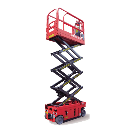
Scissor lifts
SC10H/SC12H/SC14H/SC16H/SC10E/SC12E/SC14E/SC16E/SC08HN/SC10HN/SC08EN/SC10EN
WARNING
Do not use the pallet truck before reading and
understanding these operating instructions.
NOTE:
• Keep for future reference.
NOBLELIFT INTELLIGENT EQUIPMENT CO.,LTD.
No.528 Changzhou Road,Taihu Sub-district,Changxing,Zhejiang,China
Original Instruction
Version 07/2018
SC-SMS-003-EN
Advertisement
Table of Contents

Related Manuals for Noblelift SC16H


Summary of Contents for Noblelift SC16H
- Page 1 Original Instruction Operation Safety and Maintenance Manual Scissor lifts SC10H/SC12H/SC14H/SC16H/SC10E/SC12E/SC14E/SC16E/SC08HN/SC10HN/SC08EN/SC10EN WARNING Do not use the pallet truck before reading and understanding these operating instructions. Version 07/2018 NOTE: • Keep for future reference. SC-SMS-003-EN NOBLELIFT INTELLIGENT EQUIPMENT CO.,LTD. No.528 Changzhou Road,Taihu Sub-district,Changxing,Zhejiang,China...
-
Page 2: Table Of Contents
Contents Introduction ..........................1 Symbol and Hazard Pictorials Definitions .................. 4 General Safety ........................... 6 Personal Safety .......................... 8 Work Area Safety ........................9 Legend ............................. 18 Controls ........................... 19 Inspections ..........................23 Specifications ........................... 36 Operating Instructions ......................48 Transport and Lifting Instructions ................... -
Page 3: Introduction
Introduction Important Read, understand and obey these safety rules and operating instructions before operating this machine. Only trained and authorized personnel shall be permitted to operate this machine. This manual should be considered a permanent part of your machine and should remain with the machine at all times. If you have any questions, contact us. - Page 4 Introduction Danger Failure to obey the instructions and safety rules in this manual will result in death or serious injury. Do Not Operate Unless: You learn and practice the principles of safe machine operation contained in this operator’s manual. 1 Avoid hazardous situations.
-
Page 5: Hazard Classification
Introduction Hazard Classification Decals on this machine use symbols, color coding and signal words to identify the following: Safety alert symbol—used to alert you to potential personal injury hazards. Obey all safety messages that follow this symbol to avoid possible injury or death. Indicates a hazardous situation which, if not avoided, will result in death or serious injury. -
Page 6: Symbol And Hazard Pictorials Definitions
Symbol and Hazard Pictorials Definitions... - Page 7 Symbol and Hazard Pictorials Definitions...
-
Page 8: General Safety
General Safety 602047020015 page 32~33 O utdoor Indoor 602047020014 C rushingand C ollisionH azards Approved head gear must be worn by all operating and ground M AX=12.5m /s M AX=0m /s personnel. Keep hands and limbs out of the BEWARE OF LIVE ELECTRICAL CONDUCTORS. scissor arm assembly during M AX450kg= M AX450kg=... - Page 9 602047520002 602047020009 SCISSORLIFTS MODEL SERIAL NO. Crushing Hazard Death or serious injurly can G. V. W. Noblelift Intelligent Equipment Co.,Ltd. result from contact with moving DATE OF 602047020009 No.528 Changzhou Road, Taihu Sub-district, Changxing, Zhejiang, China MANUFACTURE 602047520002 scissor arms.
-
Page 10: Personal Fall Protection
Personal Safety Personal Fall Protection Personal fall protection equipment (PFPE) is not required when operating this machine. If PFPE is required by job site or employer rules, the following shall apply: All PFPE must comply with applicable governmental regulations and must be inspected and used in accordance with the manufacturer’s instructions. -
Page 11: Work Area Safety
Do not use the machine as a ground for welding. Tip-over Hazards Occupants, equipment and materials shall not exceed the maximum platform capacity or the maximum platform capacity of the platform extension. Model Capacity SC10H/SC10E 450Kg SC12H/SC12E 320Kg SC14H/SC14E 320Kg... - Page 12 Work Area Safety Do not raise the platform unless the machine is on a firm, level surface. Do not depend on the tilt alarm as a level indicator.The tilt alarm sounds on the chassis only when the machine is on a severe slope.
- Page 13 Do not use batteries that weigh less than the original equipment. Batteries are used as counterweight and are critical to machine stability.Each battery must reach the specified weight.For SC10H/ SC10Eand SC12H/ SC12E machines, each battery must weigh 33kg. For SC14H / SC14E machines, each battery must weigh 35.5kg. For SC16H / SC16E machines, each battery must weigh 34kg.
-
Page 14: Crushing Hazard
Work Area Safety Do not place or attach fixed or overhanging loads to any part of this machine. Do not place ladders or scaffolds in the platform or against any part of this machine. Do not transport tools and materials unless they are evenly distributed and can be safely handled by person(s) in the platform. -
Page 15: Operation On Slopes Hazards
Do not drive the machine on a slope that exceeds the slope and side slope rating of the machine.Slope rating applies to machines in the stowed position. Model Maximum slope rating, stowed position Maximum side slope rating, stowed position SC10H/SC10E SC12H/SC12E SC14H/SC14E SC16H/SC16E SC08HN/SC08EN SC10HN/SC10EN Note: Slope rating is subject to ground conditions and adequate traction. -
Page 16: Collision Hazards
Work Area Safety Collision Hazards Be aware of limited sight distance and blind spots when driving or operating. Be aware of extended platform position when moving the machine. The machine must be on a level surface or secured before releasing the brakes. -
Page 17: Bodily Injury Hazard
Immediately tag and remove from service a damaged or malfunctioning machine. Be sure all maintenance has been performed as specified in this manual and the appropriate Noblelift service manual. Be sure all decals are in place and legible. -
Page 18: Battery Safety
Do not use batteries that weigh less than the original equipment. Batteries are used as counterweight and are critical to machine stability.Each battery must reach the specified weight.For SC10H/ SC10E and SC12H/ SC12E machines, each battery must weigh 33kg. For SC14H/ SC14E machines, each battery must weigh 35.5kg. For SC16H/ SC16E machines, each battery must weigh 34kg. -
Page 19: Lockout After Each Use
Work Area Safety Lifting Hazard Use the appropriate number of people and proper lifting techniques when lifting batteries. Lockout After Each Use 1 Select a safe parking location—firm level surface, clear of obstruction and traffic. 2 Lower the platform. 3 Turn the key switch to the off position and remove the key to secure from unauthorized use. -
Page 20: Legend
Legend 1 Extension pl a tform 10 Scissors a rm 2 Manual box 11 Lifting cylinder 3 Platform c ontroller 12 Ground c ontroller(on t h e oppos ite s ide of t h e m achine) 4 Fixed l a nyard 13 Entrance l a dder 5 Platform e xtension r e lease pe dal 14 Brake r e lease pum p... -
Page 21: Controls
Controls Ground control panel Chassis emergency stop switch Pull the switch out of the power supply.power on;press the switch,power off.The red mushroom shaped emergency stop switch is in the open position,the key selection switch is grounded.,and the operation power is supplied to the ground operation station key switch.In addition,the power supply of the functional control unit can be closed by using the switch in an emergency situation. -
Page 22: Platform Control Panel
Controls Platform control panel 1 Emergency s top button Push the red “emergency stop button” to the inside(off) and stop all the functions.Turn the red “emergency stop” button(on),and operate the machine. 2 Steering s witch The steering switch is a switch which is located on the top of control handle and is operate by the thumb.Press the switch on the right to drive the wheel to the right.Press the switch on the left to drive the wheel to the left. - Page 23 Controls 4 joystick c ontroller Joystick controller controls three functions:promaotion,driving,steering.After selecting the required function,the handle is operated in a series of function to achieve the function. 5 Lift b utton After pressing this button,the machine is in a state of lifting. 6 Travel/Steering button After pressing this button,the machine is in a state of travel and steering.
- Page 24 Controls --------Indicates that the chassis is located in or over an inclined notch setting.So the alarm will be heard. Note:When lifting the working platform,if the tilt indicator warning lights or alarm start,should be reduced to the working platform,and moving to a flat,solid level of ground. --------Display battery power Platform display Quantity of electricity...
-
Page 25: Inspections
Inspections Do Not Operate Unless: You learn and practice the principles of safe machine operation contained in this operator’s manual 1 Avoid hazardous situations. 2 Always perform a pre-operation inspection. Know and understand the pre-operation inspection before going on to the next section. 3 Always perform function tests prior to use. -
Page 26: Pre-Operation Inspection
Inspections Pre-operation Inspection □ Be sure that the operator’s, safety and responsibilities manuals are complete, legible and in the storage container located in the platform. □ Be sure that all decals are legible and in place.See Inspections section. □ Check for hydraulic oil leaks and proper oil level. Add oil if needed. See Maintenance section. -
Page 27: Function Test Fundamentals
Inspections Do Not Operate Unless: You learn and practice the principles of safe machine operation contained in this operator’s manual. 1 Avoid hazardous situations. 2 Always perform a pre-operation inspection. 3 Always perform function tests prior to use. Know and understand the function tests before going on to the next section. 4 Inspect the workplace. -
Page 28: At The Ground Controls
Inspections At the Ground Controls 1 Select a test area that is firm, level and free of obstruction. 2 Be sure the batteries are connected. 3 Pull out the platform and ground red Emergency Stop button to the on position. 4 Turn the key switch to ground control. -
Page 29: At The Platform Controls
Inspections Test Emergency Lowering 15 Activate the up function by pressing the lift enable button and platform up button, and raise the platform approximately 60 cm. 16 Push out the emergency descent control button. At the Platform Controls Test Emergency Stop ●... - Page 30 Inspections Test the Drive Function Button Press the drive function button 30 Wait seven seconds for the drive function to time out. 31 Slowly move the control handle in the direction indicated by the blue arrow, then in the direction indicated by the yellow arrow. ●...
- Page 31 Inspections ● Result: The machine should move in the direction that the yellow arrow points on the control panel, then come to an abrupt stop when the control handle is returned to the center position. Note: The brakes must be able to hold the machine on any slope it is able to climb. Test the Tilt Sensor Operation Note: Perform this test from the ground with the platform controller.
- Page 32 Inspections Test the Pothole Guards Note: The pothole guards should automatically deploy when the platform is raised. The pothole guards activate limit switches that allow the machine to continue to function. If the pothole guards do not deploy, an alarm sounds and the machine will not drive or steer. Raise the platform.
-
Page 33: Workplace Inspection Fundamentals
Inspections Do Not Operate Unless: You learn and practice the principles of safe machine operation contained in this operator’s manual. 1 Avoid hazardous situations. 2 Always perform a pre-operation inspection. 3 Always perform function tests prior to use. 4 Inspect the workplace. Know and understand the workplace inspection before going on to the next section. - Page 34 603547020001 Product model label(be confined only to SC10EN) 941200300006 Safety belt label 601547020002 Platform warning label 2(be confined only to SC10H/SC10E) 602047020008 Platform warning label 2(be confined only to SC12H/SC12E) 602547020002 Platform warning label 2(be confined only to SC14H/SC14E) 606547020002...
- Page 35 602047020028 Noblelift sign(1) 602047020014 Operation warning label 602047020015 Operation warning label 2 Platform warning label(be confined only to SC10H/SC10E) 601547020004 Platform warning label(be confined only to SC12H/SC12E) 602047020019 Platform warning label(be confined only to SC14H/SC14E) 602547020004 Platform warning label(be confined only to SC16H/SC16E)
- Page 36 Inspections...
- Page 37 Inspections...
-
Page 38: Specifications
Specifications SC10H 450kg Save working load 113kg Extended platform save working load Maximum number of working people(indoor) Maximum number of working people(outdoor) Maximum working height(A) Maximum platform height(B) Vehicle length(C) 2.48m 1.15m Vehicle width(D) Vehicle height(fence not folded) 2.32m 1.78m Vehicle height(fence folding)... - Page 39 Specifications SC12H 320kg Save working load 113kg Extended platform Save working load Maximum number of working people(indoor) Maximum number of working people(outdoor) Maximum working height(A) Maximum platform height(B) Vehicle length(C) 2.48m 1.15m Vehicle width(D) Vehicle height(fence not folded) 2.44m 1.92m Vehicle height(fence folding)...
- Page 40 Specifications SC14H 320kg Save working load 113kg Extended platform Save working load Maximum number of working people(indoor) Maximum number of working people(outdoor) Maximum working height(A) Maximum platform height(B) 2.48m Vehicle length(C) 1.15m Vehicle width(D) 2.58m Vehicle height(fence not folded) 2.04m Vehicle height(fence folding)...
- Page 41 Specifications SC16H 200kg Save working load 113kg Extended platform Save working load Maximum number of working people(indoor) Maximum number of working people(outdoor) 15.7m Maximum working height(A) 13.7m Maximum platform height(B) 2.48m Vehicle length(C) 1.15m Vehicle width(D) 2.58m Vehicle height(fence not folded) 2.17m Vehicle height(fence folding)...
- Page 42 Specifications SC10E 450kg Save working load 113kg Extended platform save working load Maximum number of working people(indoor) Maximum number of working people(outdoor) Maximum working height(A) Maximum platform height(B) Vehicle length(C) 2.48m 1.15m Vehicle width(D) Vehicle height(fence not folded) 2.32m 1.78m Vehicle height(fence folding)...
- Page 43 Specifications SC12E 320kg Save working load 113kg Extended platform Save working load Maximum number of working people(indoor) Maximum number of working people(outdoor) Maximum working height(A) Maximum platform height(B) Vehicle length(C) 2.48m 1.15m Vehicle width(D) Vehicle height(fence not folded) 2.44m 1.92m Vehicle height(fence folding)...
- Page 44 Specifications SC14E 320kg Save working load 113kg Extended platform Save working load Maximum number of working people(indoor) Maximum number of working people(outdoor) Maximum working height(A) Maximum platform height(B) 2.48m Vehicle length(C) 1.15m Vehicle width(D) 2.58m Vehicle height(fence not folded) 2.04m Vehicle height(fence folding)...
- Page 45 Specifications SC16E 200kg Save working load 113kg Extended platform Save working load Maximum number of working people(indoor) Maximum number of working people(outdoor) Maximum working height(A) 15.7m 13.7m Maximum platform height(B) Vehicle length(C) 2.58m 1.25m Vehicle width(D) Vehicle height(fence not folded) 2.58m 2.17m Vehicle height(fence folding)...
- Page 46 Specifications SC08HN 380kg Save working load 113kg Extended platform Save working load Maximum number of working people(indoor) Maximum number of working people(outdoor) Maximum working height(A) Maximum platform height(B) 2.48m Vehicle length(C) 0.81m Vehicle width(D) 2.24m Vehicle height(fence not folded) 1.81m Vehicle height(fence folding)...
- Page 47 Specifications SC10HN 230kg Save working load 113kg Extended platform Save working load Maximum number of working people(indoor) Maximum number of working people(outdoor) Maximum working height(A) Maximum platform height(B) 2.48m Vehicle length(C) 0.81m Vehicle width(D) 2.36m Vehicle height(fence not folded) 1.93m Vehicle height(fence folding)...
- Page 48 Specifications SC08EN 380kg Save working load 113kg Extended platform save working load Maximum number of working people(indoor) Maximum number of working people(outdoor) Maximum working height(A) Maximum platform height(B) Vehicle length(C) 2.48m 0.81m Vehicle width(D) Vehicle height(fence not folded) 2.24m 1.81m Vehicle height(fence folding)...
- Page 49 Specifications SC10EN 230kg Save working load 113kg Extended platform save working load Maximum number of working people(indoor) Maximum number of working people(outdoor) Maximum working height(A) Maximum platform height(B) Vehicle length(C) 2.48m 0.81m Vehicle width(D) Vehicle height(fence not folded) 2.36m 1.93m Vehicle height(fence folding)...
-
Page 50: Operating Instructions
Operating Instructions SC10H\SC12H\SC14H\SC16H\SC10E\SC12E\SC14E\SC16E\SC08HN\SC10HN\SC08EN \SC10EN操作说 操作说明 Do Not Operate Unless: You learn and practice the principles of safe machine operation contained in this operator’s manual. 1 Avoid hazardous situations. 2 Always perform a pre-operation inspection. 3 Always perform function tests prior to use. -
Page 51: Emergency Stop
Operating Instructions Emergency Stop Push in the red Emergency Stop button to the off position at the ground controls or the platform controls to stop all functions.Repair any function that operates when either red Emergency Stop button is pushed in. Emergency Lowering Pull the emergency lowering knob to lower the platform. - Page 52 Operating Instructions To Steer On the console of the workbench,press the drive or steering button,the button LED light up,said the machine is in the driving and steering state. To make the device shift,should be according to the joystick handle by thumb operation rocker switch,right to turn right, left to turn left.When the switch is released,the switch will return to middle of the closed position,the wheel will remain in the previously selected position.To allow the wheel to return to the middle...
- Page 53 Operating Instructions Driving on a slope Determine the slope and side slope ratings for the machine and determine the slope grade. Maximum slope rating, stowed position: 14° SC10H\SC12H\SC14H\SC16H\SC10E\SC12E SC14E\SC16E\SC08HN\SC10HN\SC08EN\SC10E Maximum side slope rating, stowed position: 14° SC10H\SC12H\SC14H\SC16H\SC10E\SC12E SC14E\SC16E\SC08HN\SC10HN\SC08EN\SC10EN Note: Slope rating is subject to ground conditions and adequate traction.
- Page 54 Operating Instructions To determine the slope grade: Measure the slope with a digital inclinometer or use the following procedure. You will need: carpenter’s level straight piece of wood, at least 1 m long tape measure Lay the piece of wood on the slope. At the downhill end, lay the level on the top edge of the piece of wood and lift the end until the piece of wood is level.
-
Page 55: Platform Overload
Operating Instructions Operational indicator codes If the platform controls LED or ground controls LCD diagnostic readout displays an operational indicator code such as LL, the fault condition must repaired or removed before resuming machine operation. Push in and pull out the red Emergency Stop button to reset the system. LED Readout LCD Readout For further information, please consult the schedule 1. -
Page 56: Overload Recovery
If the ground controls LCD diagnostic readout displays Overload Recovery, the emergency lowering system has been used while the platform was overloaded. For information on how to reset this message, please consult the appropriate Noblelift Service Manual. Operation from Ground with Controller Maintain safe distances between the operator,machine and fixed objects. -
Page 57: How To Use The Safety Arm
3 Lower the platform until the safety arm rests securely on the link. Keep clear of the safety arm when lowering the platform. How to Fold Down the Guardrails SC10H\SC12H\SC14H\SC16H\SC10E\SC12E\SC14E\SC16E\SC08HN\SC10HN\SC08EN \SC10EN The platform railing system consists of three fold down rail sections for the extension deck and three sections for the main deck. -
Page 58: To Charge Battery
Charge the battery in a well-ventilated area. Use proper AC input voltage for charging as indicated on the charger. Use only a Noblelift authorized battery and charger. To Charge Battery 1 Be sure the batteries are connected before charging the batteries. -
Page 59: Transport And Lifting Instructions
The transport vehicle must be secured to prevent rolling while the machine is being loaded. Be sure the vehicle capacity, loading surfaces and chains or straps are sufficient to withstand the machine weight. Noblelift lifts are very heavy relative to their size. See the serial label for the machine weight. - Page 60 Transport and Lifting Instructions Brake Release Operation For hydraulic driven products (SC10H/SC12H/SC14H/SC16H/SC08HN/SC10HN) 1 Chock the wheels to prevent the machine from rolling. 2 Be sure the winch line is properly secured to the drive chassis tie points and the path is clear of all obstructions.
-
Page 61: Securing To Truck Or Trailer For Transit
Transport and Lifting Instructions Securing to Truck or Trailer for Transit Always use the extension deck lock when the machine is transported. Turn the key switch to the off position and remove the key before transporting. Inspect the entire machine for loose or unsecured items. Use chains or straps of ample load capacity. - Page 62 Transport and Lifting Instructions Observe and Obey: Only qualified riggers should rig and lift the machine. Only qualified forklift operators should lift the machine with a forklift. Be sure the crane capacity, loading surfaces and straps or lines are sufficient to withstand the machine weight.
- Page 63 2.5 cm holes on the front of the machine and two holes in the ladder for lifting. 4 Adjust the rigging to prevent damage to the machine and to keep the machine level. Center of Gravity Table Model X Axis Y Axis SC10H/SC10E 87.56cm 56.93cm SC12H/SC12E 84.15cm 61.95cm 87.21cm...
-
Page 64: Maintenance Symbols Legend
Maintenance Observe and Obey: Only routine maintenance items specified in this manual shall be performed by the operator. Scheduled maintenance inspections shall be completed by qualified service technicians,according to the manufacturer’s specifications and the requirements specified in the responsibilities manual. Maintenance Symbols Legend NOTICE The following symbols have been used in this manual to help... -
Page 65: Pre-Delivery Preparation Report
Maintenance Maintenance Schedule A daily,quarterly,half yearly,every year and every two years and other five kinds of maintenance and inspection according to schedule.Product maintenance plan and pre delivery preparation report is divided into ABCDE five sub items.See the following table for each check. Inspection Checklist Daily or every 8 hours... - Page 66 Maintenance Instructions Use the operator’s manual on your machine. The Pre-delivery Preparation consists of completing the Pre-operation Inspection, the Maintenance items and the Function Tests. Use this form to record the results. Place a check in the appropriate box after each part is completed.
-
Page 67: Maintenance Inspection Report
Maintenance MAINTENANCE INSPECTION REPORT Model Serial number Date Hour meter Machine owner Inspected by (print) Inspector signature Inspector title Inspector company Instructions Make copies of this report to use for each inspection. Select the appropriate checklist(s) for the type of inspection(s) to perform. Daily or every 8 hours Quarterly or every 250 hours Semi-annually or every 500... - Page 68 Maintenance Checklist A A-1 Inspect the manuals and decals A-2 Pre-operation inspection A-3 Inspect the batteries A-4 Inspect the hydraulic oil level A-5 Function tests Perform after 40 hours: A-6 30-day service Perform after 100 hours: A-7 Grease steer yokes Checklist B Batteries Electrical wiring...
- Page 69 Maintenance Checklist C C-1 Platform overload system C-2 Replace hydraulic oil tank vent pipe Checklist D D-1 Check scissor arm wear resistant slide block D-2 Replace hydraulic oil return filter Checklist E E-1 Hydraulic oil...
-
Page 70: Checklist A Procedures
Maintenance CHECKLIST A PROCEDURES Inspect the Manuals and Decals Maintaining the operator’s and safety manuals in good condition is essential to safe machine operation. Manuals are included with each machine and should be stored in the container provided in the platform. An illegible or missing manual will not provide safety and operational information necessary for a safe operating condition. -
Page 71: Perform Pre-Operation Inspection
Maintenance 4 Always return the manuals to the storage container after use. NOTE: Contact your authorized Noblelift distributor or Noblelift if replacement manuals or decals are needed Perform Pre-operation Inspection Completing a Pre-operation Inspection is essential to safe machine operation. The Pre-operation Inspection is a visual inspection performed by the operator prior to each work shift. - Page 72 Maintenance NOTE:The following checks to be carried out in the case of sufficient battery power. 1 Wear protective clothing and wear protective glasses. 2 Ensure that the battery cable is firmly wired and not subject to corrosion. 3 Ensure the stability of the battery locking lever. 4 Take off the battery ventilation cover.
-
Page 73: Perform Function Tests
Maintenance Perform Function Tests Completing the function tests is essential to safe machine operation. Function tests are designed to discover any malfunctions before the machine is put into service. A malfunctioning machine must never be used. If malfunctions are discovered, the machine must be tagged and removed from service. - Page 74 Maintenance 1 Open the lid of the steer yokes. 2 At the top of the steer yokes,find the hole in the filling grease. 3 Fill in the steer yokes with enough grease until the grease is covered with a bearing. 4 Put back the lid.
-
Page 75: Checklist B Procedures
Maintenance CHECKLIST B PROCEDURES Inspect the Batteries This procedure be performed every 250 hours or quarterly, whichever comes first. Proper battery condition is essential to good machine performance and operational safety. Improper fluid levels or damaged cables and connections can result in component damage and hazardous conditions. - Page 76 Maintenance Models without maintenance-free or sealed batteries: 6 Remove the battery vent caps and check the specific gravity of each battery cell with a hydrometer. Note the results. 7 Check the ambient air temperature and adjust the specific gravity reading for each cell as follows: ●...
- Page 77 Maintenance 12 Install the vent caps and neutralize any electrolyte that may have spilled. a Battery b 300A fuse c Main pow er switch d Charger All models: 13 Check each battery pack and verify that the batteries are wired correctly. 14 Inspect the battery charger plug and pigtail for damage or excessive insulation wear.
-
Page 78: Inspect The Electrical Wiring
Maintenance NOTE:If you have any further questions regarding the battery charger operation, please contact the Noblelift Scissor Service Department. Inspect the Electrical Wiring This procedure be performed every 250 hours or quarterly, whichever comes first. Maintaining electrical wiring in good condition is essential to safe operation and good machine performance. - Page 79 Maintenance Keep hands clear of the safety arm when lowering the platform. 7 Inspect the center chassis area and scissor arms for burnt, chafed and pinched cables. 8 Inspect the following areas for burnt, chafed, corroded, pinched and loose wires: ●...
-
Page 80: Test The Emergency Stop
Maintenance Suitable for hydraulic driven models 3 Remove the cotter pin and check the castle nut for proper torque. NOTE: Always replace the cotter pin with a new one when removing the castle nut or when checking the torque of the castle nut. 4 Install a new cotter pin. -
Page 81: Test The Key Switch
Maintenance Result: No machine functions should operate. 3 Turn the key switch to platform control and pull out the red Emergency Stop button to the on position at both the ground and platform controls. 4 Push down the red Emergency Stop button at the platform controls to the off position. -
Page 82: Test The Automotive-Style Horn
Maintenance 5 Check the platform up/down function from the platform controls. Result: The machine functions should not operate. 6 Turn the key switch to the off position. Result: The machine functions should not operate. Test the Automotive-style Horn This procedure be performed every 250 hours or quarterly, whichever comes first. The horn is activated at the platform controls and sounds at the ground as a warning to ground personal. - Page 83 Maintenance Perform this procedure with the machine on a firm, level surface that is free of obstructions. Be sure the platform deck extension deck is fully retracted and the platform is in the stowed position. Mark a test line on the ground for reference. Turn the key switch to platform control and pull out the red Emergency Stop button to the on position at both the ground and platform controls.
- Page 84 Maintenance NOTE: The brakes must be able to hold the machine on any slope it is able to climb. 8 Replace the brake,from 1 to repeat the above process. Maximum braking distance Maximum braking distance 61cm±30cm Test the Drive Speed - Platform Stowed This procedure be performed every 250 hours or quarterly, whichever comes first.
- Page 85 Maintenance a The drive function selection button 5 Choose a point on the machine; i.e., contact patch of a tire, as a visual reference for use when crossing the test line. 6 Bring the machine to top drive speed before reaching the start line. Begin timing when the selected reference point on the machine crosses the start line.
- Page 86 Maintenance 1 Create start and finish lines by marking two lines on the ground 40 feet / 12.2 m apart. 2 Turn the key switch to platform control and pull out the red Emergency Stop button to the on position at both the ground and platform controls. 3 Press the platform up button.
- Page 87 Maintenance B-10 Test the Drive Speed - Slow This procedure be performed every 250 hours or quarterly, whichever comes first. Proper drive functions are essential to safe machine operation. The drive function should respond quickly and smoothly to operator control. Drive performance should also be free of hesitation, jerking and unusual noise over the entire proportionally controlled speed range.
-
Page 88: Perform Hydraulic Oil Analysis
Maintenance 5 Choose a point on the machine; i.e., contact patch of a tire, as a visual reference for use when crossing the start and finish lines. 6 Bring the machine to top drive speed before reaching the start line. Begin timing when the selected reference point on the machine crosses the start line. -
Page 89: Inspect The Hydraulic Tank Cap Venting System
Maintenance B-12 Inspect the Hydraulic Tank Cap Venting System This procedure be performed every 250 hours or quarterly, whichever comes first. A free-breathing hydraulic tank cap is essential for good machine performance and service life. A dirty or clogged cap may cause the machine to perform poorly. Extremely dirty conditions may require that the cap be inspected more often. - Page 90 Maintenance Maintaining the chassis tray latch components in good condition is essential to good performance and service life. Failure to detect worn out latch components may result in module trays opening unexpectedly, creating an unsafe operating condition. 1 Inspect each module tray rotary latch and related components for wear. 2 Using light oil, apply a few drops to each of the springs and to the sides of the rotary latch mechanism.
- Page 91 Maintenance 5 Turn the key switch to the off position. 6 Tag and disconnect the platform control box at the platform. 7 Follow the platform control cable down the scissor stack to the alarm bracket on the chassis deck. Tag and disconnect the platform control cable from the ECM cable at the 6-pin Deutsch connector.
- Page 92 Maintenance Result:Dignostic display will display code 18,alarm sound,and lifting function can be operated. Machine function is normal. Result:Dignostic display will not display code 18,alarm does not sound. Limit switch to be replaced. 15 Up until the potholes protection device deployment platform. Result:Dignostic display will not display code 18,alarm does not sound.Machine function is normal.
- Page 93 Maintenance 27 Lower the platform to the stowed position. Pothole Protection Switches 28 Move the machine to the maximum tilt angle that is allowed by the level of the sensor.The maximum allowable inclination angle see nameplate. 29 Press the lifting function select button,the tilt of the ground up to about 7 feet/2m from the height of the ground.
- Page 94 Maintenance 34 Press the drive function select button.Attempt to drive and steer the machine. Result:Dignostic display will display code LL,alarm sound,the steering and the driving function can not be operated. Machine function is normal. Result:Dignostic display will not display code LL,alarm does not sound,the steering and the driving function can be operated.
-
Page 95: Checklist C Procedures
Maintenance 2 Rotate the safety arm away from the machine and let it hang down. 3 Lower the platform until the safety arm fully contact the shaft bushing. Crushing hazard Keep hands clear of the safety arm when lowering the platform. 4 Open the limit switch seat cover mounted on the chassis. - Page 96 Maintenance Platform overload system is designed to prevent overload operation of the machine.It is made up of two electrical components:the overload pressure switch and the tilt sensor. The overload pressure switch is adjustable,which is used to determine the pressure of the oil cylinder.When the pressure is too large,the pressure switch will send a signal to the ECU,all the functions of the machine to stop,unit the excess load removed from the platform.
- Page 97 Maintenance Turn the key switch to ground control,raising the platform to a height of about 8 feet/2.5m from the ground. Lift the safety arm.Mobile security arm to fork sleeve middle to rotate to the vertical state. Lower the platform until the safety arm fully contact the shaft bushing. Crushing hazard Keep hands clear of the safety arm when lowering the platform.
- Page 98 Maintenance A slight rise in the platform,to restore the safety arm. 10 Lifting platform to the highest position,continue to press the function selection button. Result:Alarm sounds. Result:Alarm does not sound.Calibration platform overload system. 11 Use auxiliary drop function to lower the platform to the stowed position 12 Carefully open the limit switch short circuit.
-
Page 99: Checklist D Procedures
Maintenance Replace Hydraulic Oil Tank Breather Cap This inspection shall be carried out once every 500 hours or half a year,whichever comes first. The hydraulic tank is a vented-type tank. The breather cap has an internal air filter that can become clogged or, over time, can deteriorate. If the breather cap is faulty or improperly installed, impurities can enter the hydraulic system which may cause component damage. - Page 100 Maintenance To check the wear pads on the platform under the collapsed state. 1 Measure the distance between the inner arm cross tube and the chassis deck at the ground controls side of the non-steer end of the machine. a Wear resistant sliding block b Inner arm cross tube c Chassis de sk Result:The measurement is 13 inches / 34 mm or more.
- Page 101 Maintenance Replace the Hydraulic Tank Return Oil Filter Element This inspection shall be carried out once every 1000 hours or year,whichever comes first. Replacing the return oil filter is essential for good performance and service life of the machine.Dirty or blocked filter will affect the performance of the machine,continuous use will cause damage to the parts.Replacing the filter should be more frequent in the bad condition.
-
Page 102: Checklist E Procedures
Maintenance CHECKLIST E PROCEDURES Test or Replace the Hydraulic Oil This inspection shall be carried out once every 2000 hours or two years,whichever comes first. Replacement or testing of the hydraulic oil is essential for good machine performance and service life. Dirty oil may cause the machine to perform poorly and continued use may cause component damage. - Page 103 Maintenance Remove the hydraulic tank retaining fasteners and remove the hydraulic tank from the machine. Discharge oil plug at the bottom of the hydraulic oil tank. Drain all of the oil into a suitable container. Bodily injury hazard Spraying hydraulic oil can penetrate and burn skin. Loosen hydraulic connections very slowly to allow the oil pressure to dissipate gradually.
- Page 104 The pump can be damaged if operated without oil. Be careful not to empty the hydraulic tank while in the process of filling the hydraulic system. Do not allow the hydraulic pump appear turbid phenomenon. The Volume of Hydraulic Oil Model Hydraulic Oil Tank Hydraulic System SC10H/SC10E/SC08HN SC10HN/SC08EN/SC10EN SC12H/SC12E SC14H/SC14E SC16H/SC16E...
-
Page 105: Schematic Diagram
Schematic Diagram Symbolic sample Hydraulic cylinder Steering cylinder Hydraulic oil tank Constant pump Variable pump Engine/motor Bidirectional motor Shuttle valve Throttle orifice Filter One-way vavle Filter, Brake Flow control valve , Relief valve Bidirectional relief valve with bypass valve priority type Two way solenoid Three position two Four position two way... - Page 106 Schematic diagram Hydraulic schematic diagram SC10H/SC08HN/SC10HN...
- Page 107 Schematic diagram SC12H/SC14H/SC16H...
- Page 108 Schematic diagram SC10E/SC08EN/SC10EN...
- Page 109 Schematic diagram SC12E/SC14E/SC16E...
- Page 110 Schematic diagram Electrical schematic diagram SC10H/SC08HN/SC10HN 100Ω,10W...
- Page 111 Schematic diagram SC12H/SC14H/SC16H...
- Page 112 Schematic diagram SC10E/SC08EN/SC10EN...
- Page 113 Schematic diagram SC12E/SC14E/SC16E...
-
Page 114: Schedule 1 Fault Code
Schedule 1 Fault Code The machine Display describe The solution to guide response As seen on ECU, System Disables All ECU may be malfunctioning, replace it. initialization Fault, see also 10 Motion Check communications cable connections and As seen on ECU, System Disables All other wiring. - Page 115 Make sure that the Joystick is in the neutral (upright) position. Check the neutral zone Platform Joystick not in Diagnostic parameter setting in Dingli Scissor Programmer. neutral at power-up Message Message Only If it’s OK, consider replacing the Joystick or the PCU.
- Page 116 Look at motor enable delay with the NOBLELIFT Controller Scissor Programmer, it may be too short. Make Motor Controller SRO Fault Dependent sure other Motor Controller parameters are properly selected. Controller Check wiring. Make sure the correct throttle type Motor Controller Throttle Fault Dependent is selected in the Motor Controller.
- Page 117 Check connections to the Pump Motor. Cycle Motor Controller Pump Motor Controller power to the lift and if that does not resolve the Fault, ZAPI = Open Dependent issue, replace the Motor Controller. Check connections to the motors. Cycle power to Motor Controller Left Drive Controller the lift and if that does not resolve the issue,...
- Page 118 Platform has reached its limit of weight. Do not Over 99% Load Warning Warning Only add more load. Disables All Overloaded Platform Fault Remove the excess load immediately. Motion Brake Release mode has Disable Lifting been successfully entered. and Driving. If B.R.
-
Page 119: Schedule 2 Inspection And Maintenance Records
Schedule 2 Inspection and Maintenance Records Date. Note.
Need help?
Do you have a question about the SC16H and is the answer not in the manual?
Questions and answers