Table of Contents
Advertisement
Quick Links
Advertisement
Table of Contents

Related Manuals for Noblelift AWPS23.56

Summary of Contents for Noblelift AWPS23.56
- Page 1 AWPS-SMS-001 WARNING Must read before using this manual And the various warning label attached! Attention preservation for future use! Operation and Safety Manual AWPS23.56/AWPS46.79/AWPS46.96 Electric scissor lifts Zhejiang Noblelift Equipment Joint Stock Co. Ltd.
-
Page 2: Table Of Contents
FOREWORD ........................3 SAFETY ALERT SYMBOLS AND SAFETY SIGNAL WORDS ........4 1. SAFETY PRECAUTIONS ..................5 1.1 GENERAL ......................5 1.2 PRE-OPERATION ....................6 1.3 OPERATION ...................... 7 1.4 TOWING, LIFTING, AND HAULING ............12 1.5 MAINTENANCE ....................12 2. -
Page 3: Foreword
FOREWORD This manual is a very important tool! Keep it with the machine at all times. The purpose of this manual is to provide owners, users, operators, lessors, and lessees with the precautions and operating procedures essential for the safe and proper machine operation for its intended purpose. -
Page 4: Safety Alert Symbols And Safety Signal Words
TO ENSURE THAT THE CURRENT OWNER RECORDS ARE UPDATED AND ACCURATE. NOBLELIFT EQUIPMENT JOINT STOCK CO.,LTD. MUST BE NOTIFIED IMMEDIATELY IN ALL INSTANCES WHERE NOBLELIFT PRODUCTS HAVE BEEN INVOLVED IN AN ACCIDENT INVOLVING BODILY INJURY OR DEATH OF PERSONNEL OR WHEN SUBSTANTIAL DAMAGE HAS OCCURRED TO PERSONAL PROPERTY OR THE NOBLELIFT PRODUCT. -
Page 5: Safety Precautions
• Standards and Regulations Compliance Information • Questions Regarding Special Product Applications • Questions Regarding Product Modifications Contact: NOBLELIFT EQUIPMENT JOINT STOCK CO. LTD. No.528, Jingyi Road Economic Development Zone,Changxing,Zhejiang,China Tel:0572-6210811 Fax:0572-6128212 or Your Local NOBLELIFT Office 1. SAFETY PRECAUTIONS 1.1 GENERAL... -
Page 6: Pre-Operation
1.2 PRE-OPERATION Operator Training and Knowledge • The Operators and Safety Manual must be read in its entirety before operating the machine. • An operator must not accept operating responsibilities until adequate training has been given by competent and authorized persons. •... -
Page 7: Operation
• Check the work area for hazardous locations. Do not operate the machine in hazardous environments unless approved for that purpose by NOBLIFT. • Ensure that the ground conditions are adequate to support the maximum tire load indicated on the tire load decals located on the chassis adjacent to each wheel. - Page 8 machine. Remove the unit from service and notify the proper authorities. • Do not remove, modify, or disable any safety devices. • Never slam a control switch or lever through neutral to an opposite direction. Always return switch to neutral and stop before moving the switch to the next function.
- Page 9 • Keep both feet firmly positioned on the platform floor at all times. Never position ladders, boxes, steps, planks, or similar items on unit to provide additional reach for any purpose. • Never use the scissor arm assembly to gain access to or leave the platform. •...
- Page 10 • Maintain safe clearance from electrical lines, apparatus, or any energized (exposed or insulated) parts in accordance with the Minimum Approach Distance (M.A.D.) as specified in Table 1-1. • Allow for machine movement and electrical line swaying. Table 1-1.Minimum Approach Distances (M.A.D.) •...
- Page 11 while driving. • Do not elevate platform or drive with platform elevated while on or near a sloping, uneven, or soft surface. Ensure machine is positioned on a firm, level and smooth surface before elevating platform or driving with the platform in the elevated position. •...
-
Page 12: Towing, Lifting, And Hauling
• During operation, keep all body parts inside platform railing. • Always post a lookout when driving in areas where vision is obstructed. • Keep non-operating personnel at least 1.8 m (6 ft) away from machine during all driving operations. •... - Page 13 This section contains general safety precautions which must be observed during maintenance of this machine. Additional precautions to be observed during machine maintenance are inserted at the appropriate points in this maunual and in the Service and Maintenance Manual. It is of utmost importance that maintenance personnel pay strict attention to these precautions to avoid possible injury to personnel or damage to the machine or property.
-
Page 14: User Responsibilities, Machine Preparation & Inspection
Battery Hazards • Always disconnect batteries when servicing electrical components or when performing welding on the machine. • Do not allow smoking, open flame, or sparks near battery during charging or servicing. • Do not contact tools or other metal objects across the battery terminals. •... -
Page 15: Preparation, Inspection, And Maintenance
3. Rules of the employer and government regulations. 4. Use of approved fall protection device. 5. Enough knowledge of the mechanical operation of the machine to recognize a malfunction or potential malfunction. 6. The safest means to operate the machine where overhead obstructions, other moving equipment, and obstacles, depressions, holes, drop-offs. - Page 16 Table 2-1.Inspection and Maintenance Table Primary Service Type Frequency Reference Responsibility Qualification Before using each day; or Pre-Start User or Operator and whenever there’s an User or Operator Inspection Operator Safety Manual Operator change Service and Maintenance Pre-Delivery Before each sale, lease, or Owner, Dealer, Qualified Manual and...
- Page 17 6. Battery – Charge as required. 7. Fuel (Combustion Engine Powered Machines) – Add the proper fuel as necessary. 8. Engine Oil Supply (If equipped) - Ensure the engine oil level is at the Full mark on the dipstick and the filler cap is secure. 9.
- Page 18 Tilt Setting Tilt Setting Maximum Deck Model (front to back) (side to side) Elevation Degrees Feet Meters AWPS23.56 18.4(Full) AWPS46.79 26 (Full) AWPS46.96 31.5 (Full) Table 2-3. High Drive Speed Cutout Height Model High Drive Speed Cutout Height AWPS23.56 54 in 1.4m...
- Page 19 DO NOT OVERLOOK VISUAL INSPECTION OF CHASSIS UNDERSIDE. CHECKING THIS AREA OFTEN RESULTS IN DISCOVERY OF CONDITIONS WHICH COULD CAUSE EXTENSIVE MACHINE DAMAGE. NOTE: On each item, make sure there are no loose or missing parts, that they are securely fastened, and that no visible damage exists in addition to any other criteria mentioned.
-
Page 20: User Responsibilities And Machine Controls
1、Pothole Switch (Typical onopposite side of machine) Figure 2-2. Switch Location - 2 of 2 3. USER RESPONSIBILITIES AND MACHINE CONTROLS 3.1 GENERAL SINCE THE MANUFACTURER HAS NO DIRECT CONTROL OVER MACHINE APPLICATION AND OPERATION, CONFORMANCE WITH GOOD SAFETY PRACTICES IN THESE AREAS IS THE RESPONSIBILITY OF THE USER AND HIS OPERATING PERSONNEL. - Page 21 and maintenance of the machine undergo a thorough training program and check out period in order to become familiar with the characteristics prior to operating the machine. Persons under the influence of drugs or alcohol or who are subject to seizures, dizziness or loss of physical control must not be permitted to operate the machine.
-
Page 22: Operating Characteristics And Limitations
3.3 OPERATING CHARACTERISTICS AND LIMITATIONS General A thorough knowledge of the operating characteristics and limitations of the machine is always the first requirement for any user, regardless of user’s experience with similar types of equipment. Placards Important points to remember during operation are provided at the control stations by DANGER, WARNING, CAUTION, IMPORTANT and INSTRUCTION placards. - Page 23 Figure 3-1. AWPS4679/AWPS4696 Ground Control Station 1、Emergency Stop Switch - A two-position, red, mushroom- shaped emergency stop switch, when positioned to ON with the power selector switch positioned to ground, furnishes operating power to the ground control station. In addition, the switch can be used to turn off power to the function controls in the event of an emergency.
- Page 24 Figure 3-2. AWPS2356 Ground Control Station 1. The brakes release button(traction mode selection button) - Key switch must be chosen to chassis operation mode, and the platform dropped to its lowest level, press the switch, the vehicle brake release 2. Platform lift switch - Pressing this switch, the platform to go up. 3.
- Page 25 Figure 3-3. AWPS4679/AWPS4696 Platform Control Station 1、Emergency Stop Switch - A two-position, red, mushroom-shaped emergency stop switch functions to provide power to the platform control station and also to turn off power to the platform function controls in the event of an emergency. With the Power selector switch positioned to platform, power is turned on by pulling the switch out (on), and is turned off by pushing the switch in (off).
- Page 26 PLATFORM. NOTE: machines are equipped with a tilt interlock which cuts out drive and lift up functions when chassis is on a slope greater than what is allowable for the machine and the platform is elevated. DO NOT “LOWER” WITHOUT COMPLETELY RETRACTING THE PLATFORM EXTENSION DO NOT OPERATE MACHINE IF HIGH DRIVE SPEED OPERATES WHEN PLATFORM IS RAISED ABOVE THE STOWED POSITION.
-
Page 27: Signs
2. Horn - This push-button switch, when activated, permits the operator to warn jobsite personnel when the machine is operating in the area. 3.Turtle speed / rabbit speed selection switch - the toggle switch for selecting turtle speed forward and backward or forward and backward rabbit speed, choose a function, the switch must be moved to the correct direction to start the function. - Page 28 Please read the Risk of electric operation manual shock To maintain the Warning required clearance Figure 3-5 Warning signs and meaning Maximum wind The maximum speed is zero allowed speed The maximum Squeeze collision allowed hand risk operating force Safety belt fixed Breaking pressure point hazard...
- Page 29 Figure 3-6 The position of the label...
- Page 30 Figure 3-6 The position of the label legend...
-
Page 31: Machine Operation
4. MACHINE OPERATION 4.1 DESCRIPTION This machine is a self-propelled aerial work platform on top of an elevating ‘scissor’ mechanism. The Scissor Lift’s intended purpose is to position personnel with their tools and supplies at positions above ground level. The machine can be used to reach work areas located above machinery or equipment positioned at ground level. - Page 32 The machine is equipped with a mechanically extendable deck, giving the operator better access to worksites. On the AWPS23.56 this extension adds 3 ft (0.9 m) and on the AWPS46.79 and AWPS46.96 the extension adds 4 ft (1.2 m) to the front of the platform.
- Page 33 retracted. Maximum capacity of the deck extension is 250 lbs (120 kg). Extension of the platform in the closed or extended must use this handle lock. Fold-Down Rails DO NOT RAISE PLATFORM WITH RAILS FOLDED DOWN. THE RAILS MUST BE IN THE UPRIGHT POSITION AND PROPERLY PINNED WHEN RAISING THE PLATFORM.
-
Page 34: Steering
4.4 STEERING To steer the machine, the thumb operated steer control switch on the controller handle is positioned to the right for traveling right, or to the left for traveling left. When released, the switch will return to the center-off position and the wheels will remain in the previously selected position. -
Page 35: Parking And Stowing
4.6 PARKING AND STOWING Park and stow the machine as follows: 1. Drive the machine to a reasonably well-protected and well-ventilated area. 2. Ensure the platform is fully lowered. 3. Position the emergency stop switch to the "Off" position. 4. If necessary, cover the instruction placards, caution and warning decals so that they will be protected from hostile environment. -
Page 36: Battery Charging
4.7 BATTERY CHARGING Operation NOTE: Be sure that machine is parked in a well ventilated area before charging begins. ONLY PLUG THE CHARGER INTO A PROPERLY INSTALLED AND GROUNDED OUTLET. DO NOT USE GROUND ADAPTORS OR MODIFY PLUG. DO NOT TOUCH NON-INSULATED PORTION OF OUTPUT CONNECTOR OR NON-INSULATED BATTERY TERMINAL. -
Page 37: Platform Loading
Table 4-1. Battery Charger Flash Codes Flash(s) Fault Fault Removal Auto-recover - Indicates a high battery pack Battery voltage high voltage Auto-recover - Indicates either a battery pack failure, battery pack not connected to charger or Battery voltage low battery volts per cell is less than VDC. -
Page 38: Safety Prop
4.9 SAFETY PROP THE SAFETY PROP MUST BE USED WHENEVER MAINTENANCE PERFORMED ON THE MACHINE REQUIRES THE SCISSOR ARMS TO BE RAISED AND ONLY WITH NO LOAD IN THE PLATFORM. To engage the safety prop, raise the platform, swing the safety prop from it’s stowed position located on the right side of the machine. -
Page 39: Towing
4.12 TOWING It is not recommended that this machine be towed, except in the event of an emergency such as a machine malfunction or a total machine power failure. NOTE: The machine may be equipped with a remote electric brake release, a push button electric brake release, or both styles of electric brake release. -
Page 40: Emergency Procedures
5. EMERGENCY PROCEDURES 5.1 GENERAL This section provides information on the procedures to be followed and on the systems and controls to be used in the event an emergency situation is encountered during machine operation. Prior to operation of the machine and periodically thereafter, the entire operating manual, including this section, should be reviewed by all personnel whose responsibilities include any work or contact with the machine. - Page 41 1. Operate the machine from ground controls ONLY with the assistance of other personnel and equipment (cranes, overhead hoists, etc.) as may be required to safely remove the danger or emergency condition. 2. Other qualified personnel on the platform may use the platform controls. DO NOT CONTINUE OPERATION IF CONTROLS DO NOT FUNCTION NORMALLY.
-
Page 42: General Specifications And Operator Maintenance
Preventive Maintenance and Inspection Schedule included in the Service and Maintenance Manual. 6.2 OPERATING SPECIFICATIONS Table 6-1. Operating Specifications Model AWPS23.56 AWPS46.79 AWPS46.96 Maximum Stowed Travel... - Page 43 Table 6-2. Platform Capacities MODEL CE Extensions platform Capacity Persons Capacity Persons AWPS23.56 230 kg 113 kg AWPS46.79 460 kg 113 kg AWPS46.96 460 kg 113 kg Dimensional Data Table 6-3. Dimensions MODEL AWPS23.56 AWPS46.79 AWPS46.96 Unit of Measure feet...
-
Page 45: Critical Stability Weights
Capacities Table 6-5. Capacities Model AWPS23.56 AWPS46.79 AWPS46.96 Hydraulic Tank Hydraulic System 8.3 L 12.5L 14.2L (Including Tank) Figure 6-2 hydraulic principal Tires Table 6-6. Tire Specifications Model AWPS23.56 AWPS46.79 AWPS46.96 Size 323mm x 100mm 406 mm x 125 mm... - Page 46 Wheel/Tire and Drive 117 lbs (53 kg) 162 lbs (73.4 kg) Assembly (each) Lift Cylinder 176 lbs(80 kg) 263 lbs (119 kg) 283 lbs (128 kg) Batteries: (each) 66 lbs (30 kg) 66 lbs (30 kg) 220 Amp Lubrication NOTE: Aside from recommendations, it is not advisable to mix oils of different brands or types, as they may not contain the same required additives or be of comparable viscosities.
- Page 47 ENSURE THE SCISSOR ARMS ARE PROPERLY SUPPORTED NOTE: The AWPS46.79/AWPS46.96 platforms will have to be raised higher than the AWPS23.56 in order to access the oil plug. THERE MAY BE UP TO 10 PSI OF PRESSURE IN THE TANK. First come on, can mix oil tank filled with, and then pick up platform about 2 ~ 3 meters or so, continue refueling.
-
Page 48: Tires And Wheels
Lube - White Lithium Grease Interval - Every 6 months 1. With the platform empty, elevate machine and swing safety prop out of it’s stowed position. ENSURE THE SCISSOR ARMS ARE PROPERLY SUPPORTED. 2. Locate the Lower and Upper Slide Pads and remove all dirt and debris from the slide channel area (1, 2). -
Page 49: Appendix 1 List Of Wearing Parts
It is extremely important to apply and maintain proper wheel mounting torque. WHEEL NUTS MUST BE INSTALLED AND MAINTAINED AT THE PROPER TORQUE TO PREVENT LOOSE WHEELS, BROKEN STUDS, AND POSSIBLE SEPARATION OF WHEEL FROM THE AXLE. BE SURE TO USE ONLY THE NUTS MATCHED TO THE CONE ANGLE OF THE WHEEL. -
Page 50: Appendix 2 Inspection And Maintenance Records
Y shape circle 9000001357 60x70x10 9000001358 dust ring 60x68x5/6.5 0000022040 O-Shaped ring 35x3.1 Supporting ring 9000001359 100x95x9.7 Sealing ring100x87x8.3 9000001360 dust ring 35/43X5/38 9000001361 9000001362 Sealing ring35/45X8 O-Shaped ring 9000001363 53.57X3.53 Steering Block circle 9000001364 cylinders Sealing ring60/49X4.2 9000001365 O-Shaped ring 9000001366 34.59X2.62 Block circle... - Page 53 AWPS-BPT-001 Parts & Components Manual AWPS23.56/AWPS46.79/AWPS46.96 Electric scissor lifts Zhejiang Noblelift Equipment Joint Stock Co.,Ltd...
- Page 54 Contents Figure 1.1 Parts and componnents of platform(AWPS2356) ......2 Figure 1.2 Parts and componnents of platform(AWPS2356-G) ......5 Figure 1.3 Parts and componnents of platform(AWPS4679、AWPS4696) ... 7 Figure 1.4 Parts and componnents of platform(AWPS4679-G、AWPS4696-G) ............................. 10 Figure 2.1 Parts and componnents of scissors(AWPS2356) ......12 Figure 2.2 Parts and componnents of scissors(AWPS4679、AWPS4696)...
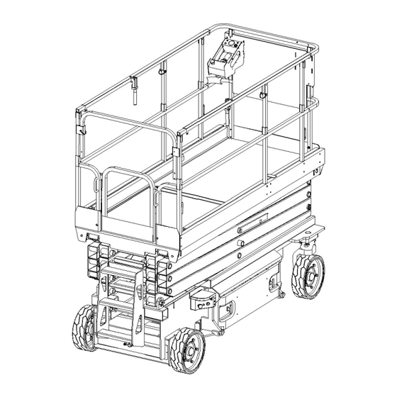
- Page 55 Figure 1.1 Parts and components of platform (AWPS2356)
- Page 56 Figure 1.1 Parts and components of platform (AWPS2356) Part Number Name Quantity Remarks Left-extended steel welding 9000001740 Right-extended steel welding 9000001742 0000024104 Locking nut 9000001378 Snap Handle guard board 9000001463 9000001440 Lever welding 9000001443 Rubber sleeve Locking nut 0000024045 Hex head bolt 0090000136 Nylon sleeve 9000001452...
- Page 57 Hex head bolt 0000023794 U-shaped block 9000001461 Extended platform welding 9000001721 Door lock 9000001901 Screw 0090000163 Tongue bars 9000001902...
- Page 58 Figure 1.2 Parts and components of platform (AWPS2356-G)
- Page 59 Figure 1.2 Parts and components of platform (AWPS2356-G) Part Number Name Quantity Remarks Outer platform welding (fixed) 9000001883 Square tube 9000001748 Door frame welding 9000001736 Core pulling rivet 0090000128 Spring hinge 9000001459 Upper hanging plate 9000001747 9000001749 Lower hanging plate 0000023870 Hex head bolt 9000001813...
- Page 60 Figure 1.3 Parts and components of platform (AWPS4679、AWPS4696)
- Page 61 Figure 1.3 Parts and components of platform (AWPS4679、AWPS4696) Part Number Name Quantity Remarks Left-extended steel welding 9000001414 Right-extended steel welding 9000001417 Locking nut 0000024104 9000001378 Snap Handle guard board 9000001463 9000001440 Lever welding 9000001443 Rubber sleeve 0000024045 Locking nut 0090000124 Hex head bolt 9000001452 Nylon sleeve...
- Page 62 Platform welding 9000001379 Extended platform welding 9000001389 Hex head bolt 0000023794 U-shaped block 9000001461 Door lock 9000001901 Screw 0090000163 Tongue bars 9000001464...
- Page 63 Figure 1.4 Parts and components of platform (AWPS4679-G、 AWPS4696-G)
- Page 64 Parts and components of platform (AWPS4679-G 、 Figure 1.4 AWPS4696-G) Part Number Name Quantity Remarks 9000001457 Upper edge of door frame 9000001703 Upper fence welding (fixed) 0000024045 Locking nut 0090000124 Hex head bolt Handle guard board 9000001463 9000001378 Snap Tongue bars 9000001464 Lever 9000001441...
- Page 65 Figure 2.1 Parts and components of platform (AWPS2356)
- Page 66 Figure 2.1 Parts and components of platform (AWPS2356) Part Number Name Quantity Remarks Upper axis slider 9000001813 Lower inner lifting fork 9000001773 9000001765 Lower outer lifting fork Upper second inner lifting fork 9000001784 Upper second outer lifting fork 9000001782 9000001786 Lower outer lifting fork Upper inner lifting fork 9000001793...
- Page 67 Figure 2.2 Parts and components of scissors (AWPS4679、AWPS4696)
- Page 68 Figure 2.2 Parts and components of scissors (AWPS4679、AWPS4696) Part Number Name Quantity Remarks 9000001466 Lower outer scissor 9000001472 Lower inner scissor Upper second outer scissor(1) 9000001484 9000001489 Upper second inner scissor Upper third outer scissor 9000001494 Upper third inner scissor 9000001496 9000001508 Upper inner scissor...
- Page 69 Figure 3.1 Parts and components of chassis (AWPS2356)
- Page 70 Figure 3.1 Parts and components of chassis (AWPS2356) Part Number Name Quantity Remarks 9000001815 Chassis 0000023055 Flat washer Screw 0000023053 9000001597 Round-shaped dust-proof cover 0000028070 Cotter pin Hex head bolt 0000023658 Hex head bolt 0000023495 0000025002 Flat washer 9000001873 Steering cylinder Steering connecting rod pin 9000001600 Steering connecting rod...
- Page 71 0090000134...
- Page 72 Figure 3.2 Parts and components of chassis (AWPS4679、AWPS4696)
- Page 73 Figure 3.2 Parts and components of chassis (AWPS4679、AWPS4696) Remarks Part Number Part Name Quantity 9000001552 Chassis 9000001607 Balance weight Balance weight 9000001606 Hex head bolt 0000023004 0090000135 Big washer Locking nut 0000023005 Hex head bolt 0000023374 0000023862 Pan head screw 0000023055 Flat washer 9000001601...
- Page 74 9000001630 Battery case welding Battery hood 9000001629 0000023055 Flat washer 0000023519 Pan head screw 9000001635 Compression lock Hex head bolt 0090000132 9000001617 Connecting plate Locking nut 0000024045 Drive axle cover 9000001626 Drive axle cover 9000001627 9000001625 Drive axle connecting shaft Retaining pin 9000001535 Screw...
- Page 75 Figure 3.3 Side supporting device (AWPS2356)
- Page 76 Figure 3.3 Side supporting device (AWPS2356) Part Number Name Quantity Remarks Hex head bolt 0000023658 0000023005 Locking nut Gasket 0000025106 9000001800 Bracket Spring washer 0000026013 Spring 9000001526 Steering rod 9000001525 Top sleeve 9000001527 Side supporting plate welding 9000001860 Pin roll of supporting plate 9000001613 Spring washer 0000026013...
- Page 77 Figure 3.4 Side supporting device (AWPS4679、AWPS4696)
- Page 78 Figure 3.4 Side supporting device (AWPS4679、AWPS4696) Part Number Name Quantity Remarks 0000023658 Hex head bolt 0000023005 Locking nut Gasket 0000025106 9000001520 Bracket 0000026013 Spring washer Spring 9000001526 Steering rod 9000001525 9000001527 Top sleeve 9000001608 Side supporting plate welding 9000001613 Pin roll of supporting plate Spring washer 0000026013 9000001615...
- Page 79 Figure 4. Steering cylinder...
- Page 80 Figure 4. Steering cylinder Remarks Part Number Part Name Quantity O-shaped ring 9000001366 O-shaped ring 9000001363 9000001364 Retainer ring 9000001362 Seal ring for rod Dust-proof ring 9000001361 Seal ring for hole 9000001365 9000001688 AWPS4679 Stopping tube AWPS2356 9000001874 Retainer ring for shaft 9000001367 Oil tube connector 9000001673...
- Page 81 Figure 5.1 Lifting cylinder (AWPS2356)
- Page 82 Figure 5.1 Lifting cylinder (AWPS2356) Part Number Name Quantity Remarks Compound sleeve 0000027006 9000001868 Piston rod O-shaped ring 0000022099 Dust-proof ring 9000001371 9000001370 Y-shaped ring for axis 9000001869 Nut cap 9000001368 O-shaped ring 9000001369 Guide ring Piston 9000001870 Hexagon nut 0090000110 Piston support ring 9000001372...
- Page 83 Figure 5.2 Lifting cylinder (AWPS4679、AWPS4696)
- Page 84 Figure 5.2 Lifting cylinder (AWPS4679、AWPS4696) Part Number Name Quantity Remarks Compound sleeve 9000001664 Piston rod 9000001662 0000022040 O-shaped ring 9000001358 Dust-proof ring Y-shaped ring for axis 9000001357 Cap nut 9000001663 9000001355 O-shaped ring Guide ring 9000001356 Piston 9000001665 Hexagon nut 0090000149 9000001359 Piston support ring...
- Page 85 Figure 6 Parts and components of pump station...
- Page 86 Figure 6 Parts and components of pump station Part Number Name Quantity Remarks O-shaped ring 9000002219 Bolt 9000002220 Lock nut 9000002221 Bolt 9000002222 Gasket 9000002223 Hoop 9000002224 AWPS4696 9000002225 Cylinder AWPS4679 9000002226 AWPS2356 9000002226 101A Refuelling plug 9000002227 101B Bolt 9000002228 101C Magnet...
- Page 87 Gear pump 9000002246 104A Seal ring 9000002247 Components of safety valve 9000002248 105A Seal ring 9000002249 Power box 9000002250 106A Seal ring 9000002251 106B Seal ring 9000002252 106C Bolt 9000002253 106D Sleeve 9000002254 106E Spring pin 9000002255 106F Seal ring 9000002256 106G Locking tab...
- Page 88 Figure 7.1 Electrical parts (AWPS2356)
- Page 89 Figure 7.1 Electrical parts (AWPS2356) Part Number Name Quantity Remarks platform electrical box 9000001751 Battery 9000001636 1020434006 Socket connector Screw 0000023090 Charger 9000001639 0000023055 Flat washer 0000023053 Screw 0000023042 Screw Flat washer 0000023055 3002434013 Reversing ACCESS Controller 9000001846 Screw 0000023688 Safety limit switch 9000001856 9000001638...
- Page 90 Locking nut 0000024045 Screw 0090000241 9000002342 Limit switch...
- Page 91 Figure 7.2 Electrical parts (AWPS4679、AWPS4696)
- Page 92 Figure 7.2 Electrical parts (AWPS4679、AWPS4696) Part Number Name Quantity Remarks 9000001418 platform electrical box 9000001636 Battery 9000001158 Geared Motor 1020434006 Socket connector 0000023090 Hexagon 9000001639 Charger 0000023055 Flat washer 0000023040 Screw 9000002343 Tilt sensor 0000025014 Flat washer 0000023076 Screw 0000023042 Screw 0000023055 Flat washer...
- Page 93 0000023538 Pan head screw 0090000131 Hex head bolt 9000001532 Weighing sensor 0000023005 Locking nut 9000001856 Safety limit switch 9000001638 Switch seat 0000023090 Screw 0000023055 Flat washer 0000024045 0090000241 Screw Fixed board 9000001649 0000023041 Pan head screw 0000024004 Locking nut 0000024045 Locking nut 0090000241 Screw...
- Page 94 Figure 7.3 Platform electrical box (AWPS2356)
- Page 95 Figure 7.3 Platform electrical box (AWPS2356) Part Number Name Quantity Remarks Pan head screw 0000023516 class flat washer 0000025014 Welding of hanging plat 9000001758 9000001432 Button switch 9000001431 Button switch 9000001752 platform electrical box Pan head screw 0000023071 JIM display board 9000001761 9000001429 Operational lever...
- Page 96 Figure 7.4 Platform electrical box (AWPS4679、AWPS4696)
- Page 97 Figure 7.4 Platform electrical box (AWPS4696) Part Number Name Quantity Remarks 0000023534 Pan head screw 0000023032 Flat washer Left plate 9000001419 Emergency stop switch 1010434024 9000001421 Welding of the rear box 9000001437 Lever cover Front cover plate 9000001438 Welding of the front box 9000001425 9000001432 Button switch...
- Page 98 Figure 7.5 Chassis electrical box (AWPS4679、AWPS4696) Figure 7.5 Chassis electrical box (AWPS4679、AWPS4696) Part Number Name Quantity Remarks chassis electrical operation box 9000001651 Rear cover plate 9000001660 0090000041 Screw Metal lamp 9000001430 9000001430 Metal lamp 1070334006 Button switch 9000001659 Key switch Button switch 9000001658 Emergency stop switch...
- Page 99 Figure 7.6 Components of aluminium plate...
- Page 100 Figure 7.6 Components of aluminium plate Part Number Name Quantity Remarks 9000001604 Electrical installation board 9000001603 Controller 0000023020 Hexagon Elastic pad 0000025010 0000023055 Flat pad Pan head screw 0000023076 Elastic pad 0000025015 0000025014 Flat pad 9000001605 Contactor mounting plate Pan head screw 0000023716 Contactor 2390434003...
Need help?
Do you have a question about the AWPS23.56 and is the answer not in the manual?
Questions and answers