Table of Contents
Advertisement
Quick Links
30440 Agoura Road
Agoura Hills, CA 91301 USA
Toll Free: (800) 253-2363
Tel: (805) 933-9970
rangerproducts.com
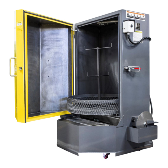
Spray-Wash Cabinets
Installation and Operation Manual
Manual P/N 5900245 — Manual Revision C4 — June 2024
Models:
• RS-500-D-503
• RS-750-D-503
• RS-500-D-601
• RS-750-D-601
• RS-500-DS-601
• RS-750-DS-601
Powder Coated Model Shown
Designed and engineered by BendPak Inc. in Southern California, USA. Made in China.
⚠
DANGER
Read the entire contents of this manual before using this product. Failure to follow the
instructions and safety precautions in this manual can result in serious injury or death. Make sure all
other operators also read this manual. Keep the manual near the product for future reference.
By
proceeding with setup and operation, you agree that you fully understand the contents of
.
this manual and assume full responsibility for product use
Advertisement
Table of Contents

Related Manuals for Ranger RS-500DS


Summarization of Contents
Safety Considerations
Safety Information
General safety rules for operation, personnel, and environment.
California Proposition 65 Warning
Warning about chemical exposure and associated health risks.
Operation Guide
About Detergent
Recommends specific detergents and provides guidelines for selection.
Start-Up Process
Detailed steps for initial machine preparation and break-in.
Maintenance
Regular Maintenance
Daily, monthly, and periodic maintenance tasks for optimal function.
Removing Sludge
Procedure for cleaning the water reservoir to prevent damage.
Cleaning Spray Nozzles
Steps to clear clogged nozzles for effective cleaning.
Environmental Issues
Guidelines for proper disposal of waste solutions and sludge.
Wiring Diagrams
1 Phase Wiring Schematic
Shows the electrical connections for single-phase units.
1 Phase Terminal Block Diagram
Illustrates terminal block connections for single-phase units.
3 Phase Wiring Schematic
Shows the electrical connections for three-phase units.
3 Phase Terminal Block Diagram
Illustrates terminal block connections for three-phase units.
Need help?
Do you have a question about the RS-500DS and is the answer not in the manual?
Questions and answers