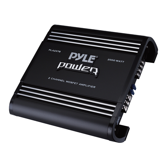
Summary of Contents for Pyle PLA2678
- Page 1 Visit Our Website SCAN ME PyleUSA.com PLA2378 - PLA2678 - PLA2978 - PLA4278 PLA4478 - PLA1800 - PLA3100D - PLA4600D High Speed Car Amplifier USER GUIDE...
- Page 2 Pyle, founded in the 1960s, has evolved into a renowned manufacturer of high-quality advanced woofers. Our journey started with the iconic Pyle Driver, becoming a household name in original speakers. In the late 20th century, we expanded into replacement speakers, car audio, home audio, marine audio, and professional audio &...
-
Page 3: California Prop 65 Warning
CONTENTS GENERAL FEATURES FEATURES AND CONTROLS ELECTRICAL CONNECTIONS STEREO INPUT CONNECTIONS MONO INPUT CONNECTIONS PLMRA220 2/4 CHANNEL INPUT CONNECTIONS HIGH LEVEL INPUT CONNECTIONS MONO INPUT CONNECTIONS PLMRA420 HIGH LEVEL MONO INPUT CONNECTIONS SPEAKER CONNECTIONS MOUNTING AND INSTALLATION PRECAUTIONS PROTECTION CIRCUITRY TROUBLESHOOTING FCC CAUTION IC WARNING... -
Page 4: Installation
Congratulations on purchasing the High-Speed Power Ampli er! This ampli er has been designed with the latest electronic technology to deliver high-quality stereo reproduction for mobile applications. It features low harmonic distortion, substantial reserve voltage, and excellent temperature stability. Enjoy the perfect sound that this ampli er brings to you! INSTALLATION •... -
Page 5: Power Connection
POWER CONNECTION IMPORTANT: Before making any connections, disconnect the car’s battery to avoid possible damage to the electrical system. • The +12V DC power cable should be heavy-gauge, stranded copper wire with heavy insulation, as it draws power directly from the positive battery terminal. The cable gauge should be at least 10mm², and the ground cable should be the same gauge. - Page 6 2 CHANNEL AMPLIFIER — FEATURES (PLA2378) High Pass Filter: Variable from 40Hz to 300Hz. Low Pass Filter: Input Level: Adjusts line level (RCA) Variable from 40Hz to 300Hz. inputs from Min to Max. Bass EQ: Adjusts bass Mono/Stereo Line Input: Accepts line-level (RCA) boost from 0dB to 12dB.
- Page 7 2 CHANNEL AMPLIFIER — FEATURES (PLA2678) High Pass Filter: Remote Control: Adjusts the low-pass Variable from 40Hz to 300Hz. signal via the included remote. Low Pass Filter: Variable from 40Hz to 300Hz. Input Level: Adjusts line level (RCA) inputs from Min to Max. Bass EQ: Adjusts bass Mono/Stereo boost from 0dB to 12dB.
- Page 8 2 CHANNEL AMPLIFIER — FEATURES (PLA2978) High Pass Filter: Remote Control: Adjusts the low-pass Variable from 40Hz to 300Hz. signal via the included remote. Low Pass Filter: Variable from 40Hz to 300Hz. Input Level: Adjusts line level (RCA) inputs from Min to Max. Bass EQ: Adjusts bass Mono/Stereo boost from 0dB to 12dB.
- Page 9 4 CHANNEL AMPLIFIER — FEATURES (PLA4278/PLA4478) Line Input: Accepts line-level (RCA) High Pass: Variable High Pass inputs from 0.2 to 6.0 volts. Filter from 15Hz to 250Hz. Input Level: Adjusts line-level (RCA) Low Pass: Variable Low Pass inputs from 0.2 to 6.0 volts. Filter from 60Hz to 200Hz.
- Page 10 MONO CHANNEL AMPLIFIER — FEATURES (PLA1800) Subsonic Filter: Sets the lower cuto frequency, variable from 10Hz to 40Hz. Low Pass: Variable Low Pass Filter from 40Hz to 300Hz. Remote Control: Adjusts the low pass Input Level: Accepts line-level (RCA) signal via the enclosed remote control. inputs from 0.4 to 4 volts.
- Page 11 MONO CHANNEL AMPLIFIER — FEATURES (PLA3100D/PLA4600D) Remote Control: Adjusts the low pass signal via the enclosed remote control. Bass EQ: Adjusts the Bass Boost from 0dB to 12dB. Mode: Allows you to select either the MASTER OUTPUT Subsonic Filter: Sets the lower cuto mode or SLAVE INPUT.
-
Page 12: Channel Amplifier - Applications
2 CHANNEL AMPLIFIER — APPLICATIONS Input Connections • This ampli er has RCA connections for low-level inputs, which carry the signal through RCA cables. It is preferred to use low-level inputs to the ampli er if the head unit is equipped with low-level outputs. •... -
Page 13: Stereo Mode
2 CHANNEL AMPLIFIER — APPLICATIONS PLA2378 / PLA2678 / PLA2978 STEREO MODE MONO MODE www.PyleUSA.com... -
Page 14: Channel Mode
MONO CHANNEL AMPLIFIER — FEATURES (PLA4278/PLA4478) 4-CHANNEL MODE www.PyleUSA.com... - Page 15 MONO CHANNEL AMPLIFIER — FEATURES (PLA4278/PLA4478) 3-CHANNEL MODE 2-CHANNEL MODE www.PyleUSA.com...
- Page 16 MONO AMPLIFIER — APPLICATIONS Input Connections • This ampli er has RCA connections for low-level inputs. Low-level signals are carried through RCA cables. It is preferred to use low-level inputs to the ampli er if the head unit is equipped with low-level outputs.
- Page 17 MONO AMPLIFIER — APPLICATIONS (PLA1800) www.PyleUSA.com...
- Page 18 MONO AMPLIFIER — APPLICATIONS (PLA3100D/PLA4600D) www.PyleUSA.com...
- Page 19 MONO CHANNEL AMPLIFIER — APPLICATIONS (PLA3100D / PLA4600D) MASTER/SLAVE Link MASTER SLAVE MASTER SLAVE www.PyleUSA.com...
- Page 20 MONO CHANNEL AMPLIFIER — APPLICATIONS (PLA3100D / PLA4600D) INTERCONNECTION EXAMPLES Subwoofer with a Single Voice Coil MASTER SLAVE www.PyleUSA.com...
- Page 21 MONO CHANNEL AMPLIFIER — APPLICATIONS (PLA3100D / PLA4600D) INTERCONNECTION EXAMPLE Subwoofer with a Dual Voice Coil MASTER SLAVE Subwoofer with a Single Voice Coil (1-8 Ohm) MASTER SLAVE Subwoofer 2 1-8 Ohm The subwoofer on the SLAVE amp needs to be connected with reverse polarity.
-
Page 22: Specification
SPECIFICATION All speci cations subject to change without notice. FCC Caution This device complies with part 15 of the FCC Rules. Operation is subject to the following two conditions: (1) This device may not cause harmful interference, and (2) this device must accept any interference received, including interference that may cause undesired operation. -
Page 23: Register Product
• Reorient or relocate the receiving antenna. • Increase the separation between the equipment and receiver. • Connect the equipment into an outlet on a circuit di erent from that to which the receiver is connected. • Consult the dealer or an experienced radio/TV technician for help. The device has been evaluated to meet general RF exposure requirement. - Page 24 Questions or Comments? We are here to help! Phone: 1.718.535.1800 PyleUSA.com/ContactUs...


Need help?
Do you have a question about the PLA2678 and is the answer not in the manual?
Questions and answers