Table of Contents
Advertisement
Quick Links
ITC V3, ITC V3 PRO
SIMATIC HMI
Industrial Thin Clients
ITC V3, ITC V3 PRO
Operating Instructions
Firmware version V3.2
03/2024
A5E42761061-AF
Preface
Overview
Safety instructions
Installing and connecting
the device
Operating the device
ITC Operating mode
SINUMERIK operating mode
Device maintenance and
repair
Technical specifications
Technical Support
Markings and symbols
Abbreviations
1
2
3
4
5
6
7
8
A
B
C
Advertisement
Table of Contents

Related Manuals for Siemens 6AV6646-1BA22-1AA1


Summary of Contents for Siemens 6AV6646-1BA22-1AA1
- Page 1 ITC V3, ITC V3 PRO Preface Overview SIMATIC HMI Safety instructions Installing and connecting the device Industrial Thin Clients ITC V3, ITC V3 PRO Operating the device ITC Operating mode Operating Instructions SINUMERIK operating mode Device maintenance and repair Technical specifications Technical Support Markings and symbols Abbreviations...
-
Page 2: Legal Information
Note the following: WARNING Siemens products may only be used for the applications described in the catalog and in the relevant technical documentation. If products and components from other manufacturers are used, these must be recommended or approved by Siemens. Proper transport, storage, installation, assembly, commissioning, operation and maintenance are required to ensure that the products operate safely and without any problems. -
Page 3: Preface
Preface Purpose of the operating instructions These operating instructions provide information based on the requirements defined by mechanical engineering documentation for manuals. This information relates to the place of use, transport, storage, mounting, use and maintenance. These operating instructions are intended for the following user groups: •... - Page 4 V3.2: ITC V3 devices 12" Designation Type Display / Article number, device Article number, device resolution with Siemens logo without Siemens logo ITC1200 V3 Built-in unit 12" HD 6AV6646-1BA12-0AA1 6AV6646-1BA12-0NA1 ITC1200 V3 PRO PRO device for pedestal 12"...
- Page 5 Preface ITC V3 devices 22" Designation Type Display / Article number, device Article number, device resolution with Siemens logo without Siemens logo ITC2200 V3 Built-in unit 22" Full HD 6AV6646-1BA22-1AA0 6AV6646-1BA22-1NA0 22" Full HD 6AV6646-1BA22-1AA1 6AV6646-1BA22-1NA1 ITC2200 V3 PRO PRO device for pedestal 22"...
- Page 6 1. After you receive your product, download the relevant documentation, at a time no later than the first assembly/commissioning. Use the following options for the download: – Technical Support (https://support.industry.siemens.com): The documentation is assigned to the product via the article number. The article number can be found on the product and on the packaging label.
-
Page 7: Style Conventions
Preface Style conventions The following text notation will facilitate reading this manual: Text markup Example Meaning Text in quotation marks: "Add screen" • Terminology that appears in the "Text" user interface, for example dialog names, tabs, buttons, menu commands • Required input, for example, limits, tag values. - Page 8 Preface Figures This manual contains illustrations of the described devices. The figures can deviate from the particularities of the delivered device. Picture parts are marked with black position numbers on a white background: ①, ②, ③, ... Work steps within the figures are marked with white process numbers on a black background according to the sequence to be followed: , ...
-
Page 9: Table Of Contents
Table of contents Preface ..............................3 Overview .............................. 13 Product description ......................13 Product package ........................ 16 Layout of the devices ......................17 1.3.1 ITC V3 built-in units......................17 1.3.2 ITC V3 PRO devices......................19 1.3.2.1 Overview ........................... 19 1.3.2.2 PRO devices for support arm (not extendable, flange top) ........... - Page 10 Table of contents Installing a PRO device ....................... 52 3.3.1 Notes on mounting ......................52 3.3.2 PRO devices for support arm (not extendable, flange top) and for pedestal (extendable, flange bottom) ........................53 3.3.3 PRO devices for support arm (extendable, round tube) ............55 Connecting the device .......................
- Page 11 Table of contents Configuring the server ..................... 111 5.6.1 RDP ..........................111 5.6.1.1 RDP overview ........................111 5.6.1.2 Administration on the server .................... 112 5.6.2 Citrix ..........................113 5.6.2.1 Citrix overview ......................... 113 5.6.2.2 Connecting to a Citrix application or a desktop ..............114 5.6.2.3 Restrictions ........................
- Page 12 Table of contents Device maintenance and repair ......................165 General information on maintenance and servicing ............165 Cleaning the device ......................165 Spare parts and repairs ....................166 Recycling and disposal ..................... 166 Technical specifications ........................167 Labels, certificates and approvals ..................167 Electromagnetic compatibility ..................
-
Page 13: Overview
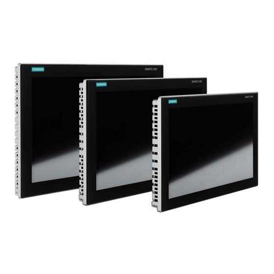
Overview Product description SIMATIC ITC - the high-performance local thin client solution Industrial Thin Clients are low-cost HMI terminals that provide local HMI functionality in plants spread over large areas. In this way, Industrial Thin Clients contribute to an improved overview, operability, and productivity of plants. - Page 14 Overview 1.1 Product description ITC Operating mode In the ITC operating mode, the Industrial Thin Client always communicates with a host, such as an HMI device, industrial PC, or server, via the following connection types: • Web browser functionality • SIMATIC WinCC Sm@rtServer •...
- Page 15 Overview 1.1 Product description Features Installation compatibility The Industrial Thin Client built-in units are compatible with SIMATIC Industrial PCs, Industrial Flat Panels, HMI devices and SINUMERIK TOP Panels of the same series. Front • Integrated glass front, anti-reflective coating, resistant to scratches and chemicals •...
-
Page 16: Product Package
Overview 1.2 Product package Product package The following components are included in the scope of delivery of the device: Designation Figure Quantity HMI device Installation instructions (Quick Installation Guide) Power supply connector Mounting clips with Steel mounting clip, captive screw For built-in units Strain relief bracket For built-in units... -
Page 17: Layout Of The Devices
Layout of the devices 1.3.1 ITC V3 built-in units The following figures show the structure of the Industrial Thin Clients using an example of the SIMATIC ITC1900 V3 built-in units with Siemens logo. Front view and side view ① Capacitive touch screen ②... - Page 18 Overview 1.3 Layout of the devices Rear view ① Rating plate ② Cover ③ Interface designation ITC V3, ITC V3 PRO Operating Instructions, 03/2024, A5E42761061-AF...
-
Page 19: Itc V3 Pro Devices
Overview 1.3 Layout of the devices 1.3.2 ITC V3 PRO devices 1.3.2.1 Overview The PRO devices are available in the following variants. The figures show examples. • PRO devices for support arm (not extendable, flange top) These devices are designed for mounting on a support arm without extensions such as Extension Units. -
Page 20: Pro Devices For Support Arm (Not Extendable, Flange Top)
PRO devices for support arm (not extendable, flange top) The following figures show the structure of the devices using the example of the ITC2200 V3 PRO for support arm (not extendable, flange top) with Siemens logo. Front view and side view ①... -
Page 21: Pro Devices For Pedestal (Extendable, Flange Bottom)
1.3.2.3 PRO devices for pedestal (extendable, flange bottom) The following figures show the structure of the devices using the example of the ITC2200 V3 PRO for pedestal (extendable, flange bottom) with Siemens logo. Front view and side view ① Display with touch screen ②... - Page 22 Overview 1.3 Layout of the devices Bottom view ① Mechanical interface for fastening Rear view ① Backplane cover ② Terminal compartment cover ③ Rating plate ④ Mechanical interface for fastening ITC V3, ITC V3 PRO Operating Instructions, 03/2024, A5E42761061-AF...
-
Page 23: Pro Devices For Support Arm (Extendable, Round Tube)
PRO devices for support arm (extendable, round tube) The following figures show the structure of the devices using the example of the ITC1500 V3 PRO for support arm (extendable, round tube) with Siemens logo. Front view and side view ①... -
Page 24: Interfaces
Overview 1.3 Layout of the devices 1.3.3 Interfaces The following figures show the interfaces of the ITC V3 devices. Built-in units PRO devices ① Functional grounding connection ④ X1 P1 PROFINET (LAN), 10/100/1000 MBit ② X80 power supply connector ⑤ X1 P2 LAN, 10/100/1000 MBit ③... -
Page 25: System Components And Accessories
Mechanical interface to the PRO device ④ Cover ⑤ Mechanical interface to the support arm or pedestal including seal Article number: 6AV7674-1KA00-0AA0 You can find the associated documentation on the Internet (https://support.industry.siemens.com/cs/ww/en/view/32109730). ITC V3, ITC V3 PRO Operating Instructions, 03/2024, A5E42761061-AF... - Page 26 You can find the associated documentation on the Internet (https://support.industry.siemens.com/cs/ww/en/view/32109730). In addition, other manufacturers are offering support arm or pedestal systems with mechanical interface or adapter for Siemens PRO devices, for example, RITTAL, ROLEC, BERNSTEIN, HASEKE, ROSE. Observe the technical specifications of the respective manufacturer.
- Page 27 Mechanical interface to support arm Article number: 6AV7674-1KF00-0AA0 You can find the associated documentation on the Internet (https://support.industry.siemens.com/cs/ww/en/view/32109730). Round tube plug If you do not need the mechanical interface of a PRO device for support arm (extendable, round tube) you can install the round tube plug into the mechanical interface. With the round tube plug, the degree of protection IP65 is maintained all around for the PRO device.
-
Page 28: Mounting Options
Overview 1.4 System components and accessories Extensions for PRO devices The following example shows a PRO device for a support arm (extendable, round tube) with Extension Unit, Extension Unit box as well as the PRO Options Handles and Keyboard tray with Keyboard tray plate. - Page 29 In addition, different operator controls, such as Emergency Stop pushbutton, selector switch, illuminated pushbutton, keyswitch or indicator light are available. Note Only operator controls with Siemens approval may be installed in the Extension Unit. You can find detailed information in the corresponding operating instructions on the Internet (https://support.industry.siemens.com/cs/ww/en/view/109742323).
- Page 30 KP12 keypads. Free slots can be equipped with Standard/Advanced and Safety operator controls. Note Only operator controls with Siemens approval may be installed in the Extension Unit. Extension Units Advanced minimum configuration with 1 x KP12 for PROFINET: • Extension Unit 12" KP12 PN, article number 6AV2185-8CE01-0AA0 •...
- Page 31 • Extension Unit box 22", article number 6AV7674-1LA60-0AA0 • Extension Unit box 24", article number 6AV7674-1LA70-0AA0 You can find the associated documentation on the Internet (https://support.industry.siemens.com/cs/ww/en/view/109761025). Handles The width of the handles can be adjusted so that the entire device can be aligned or positioned without having to touch the display of the PRO device.
-
Page 32: Additional Information
The keyboard tray plate has sufficient space for the keyboard and the mouse. Article number: 6AV7674-1NG00-0AA0 You can find the associated documentation on the Internet (https://support.industry.siemens.com/cs/ww/en/view/109761024). Replacement adapter The Replacement adapter simplifies the dismantling and mounting of a Extension Unit, that are mounted below a SIMATIC PRO device of the "extendable"... -
Page 33: Accessories
Industry Mall under the respective article numbers. You can find an overview of the status and compatibility of the accessories portfolio in the "Cross-List" on the Internet (https://support.industry.siemens.com/cs/ww/en/view/40466415). HMI I/O components Designation... -
Page 34: Other Accessories
You can find more information and important tips on the Internet (https://support.industry.siemens.com/cs/ww/en/view/109806812). Other accessories Additional USB accessories can be found on the Internet in the following entry: FAQ 19188460 (https://support.industry.siemens.com/cs/ww/en/view/19188460). ITC V3, ITC V3 PRO Operating Instructions, 03/2024, A5E42761061-AF... -
Page 35: Safety Instructions
Safety instructions General safety instructions The device is designed for use in the industrial sector for operating and monitoring plant processes. Observe the safety and accident prevention instructions applicable to your application in addition to the safety information given in the device documentation. Safety of the plant or system NOTICE The planner is responsible for the safety. -
Page 36: Industrial Security
Siemens’ products and solutions undergo continuous development to make them more secure. Siemens strongly recommends that product updates are applied as soon as they are available and that the latest product versions are used. Use of product versions that are no longer supported, and failure to apply latest updates may increase customer’s exposure to... -
Page 37: Security Management For Hmi Devices
This product includes third-party software. Siemens Aktiengesellschaft only provides a warranty for updates/patches for the third-party software if such updates/patches have been distributed as part of a Siemens software update service contract or officially released by Siemens Aktiengesellschaft. Otherwise, updates/patches are undertaken at your own risk. -
Page 38: Notes About Usage
Safety instructions 2.4 Notes about usage Notes about usage NOTICE The HMI device is approved for indoor use only The HMI device may be damaged if it is operated outdoors. Operate the HMI device only indoors ("Indoor use only"). Note Operate the device only in a normal atmospheric environment The technical characteristics of the device described in the operating instructions are guaranteed if you operate the device in normal ambient air conditions with usual air... - Page 39 Safety instructions 2.4 Notes about usage Use in residential areas Note HMI device not intended for use in residential area The HMI device is not intended for use in residential areas. Operation of an HMI device in residential areas can have a negative influence on radio or TV reception. Use with additional measures The HMI device should not be used at the following locations unless additional measures are taken:...
-
Page 40: Use In Hazardous Areas
Safety instructions 2.5 Use in hazardous areas Use in hazardous areas The following warnings apply to operating a device with Ex approval in hazardous areas. WARNING Do not plug or pull connectors in potentially explosive atmospheres If you plug in or pull out connecting plugs during operation, there is a risk of sparkover. An explosion can be triggered in the hazardous area due to sparkover, and death or serious physical injury can occur. -
Page 41: Installing And Connecting The Device
A damaged part will cause the HMI device to malfunction. Do not install parts damaged during shipment. In the case of damaged parts, contact your Siemens representative. Check the scope of supply of the HMI device (see Product package (Page 16)). -
Page 42: Checking The Operating Conditions
Installing and connecting the device 3.1 Preparing for installation 3.1.2 Checking the operating conditions Note the following aspects before installing the HMI device: 1. Familiarize yourself with the standards, approvals, EMC parameters and technical specifications for operation of the HMI device. This information is available in the following sections: –... -
Page 43: Checking Clearances
Installing and connecting the device 3.1 Preparing for installation Mounting in landscape format Mounting in portrait format Note Portrait format must also be supported by the software Only install the HMI device in portrait format when the software used supports portrait format. -
Page 44: Preparing The Mounting Cutout
Installing and connecting the device 3.1 Preparing for installation 3.1.3.3 Preparing the mounting cutout Note Stability of the mounting cutout The material in the area of the mounting cutout must provide sufficient strength to guarantee the enduring and safe mounting of the HMI device. The force of the mounting clips or operation of the device may not lead to deformation of the material in order to achieve the degrees of protection described below. -
Page 45: Installing A Strain Relief
Installing and connecting the device 3.1 Preparing for installation 3.1.3.4 Installing a strain relief Requirement For the assembly of the strain relief bracket you require: • The strain relief bracket from the scope of delivery • A torque screwdriver with a T20 bit Procedure Fasten the strain-relief with the screws intended for this purpose, torque 0.8 Nm. -
Page 46: Pro Devices
Installing and connecting the device 3.1 Preparing for installation 3.1.4 PRO devices 3.1.4.1 Permitted mounting positions The device is intended for mounting on a support arm or stand. The following figures show the permissible mounting positions of the different PRO devices. PRO devices for support arm (not extendable, flange top) and for pedestal (extendable, flange bottom) PRO devices for support arm (extendable, round tube) -
Page 47: Installing A Strain Relief
Installing and connecting the device 3.1 Preparing for installation 3.1.4.2 Installing a strain relief Requirement For the assembly of the strain relief bracket you require: • The strain relief bracket from the scope of delivery • A torque screwdriver with a T20 bit Procedure Mount the strain relief plate as follows: 1. -
Page 48: Installing The Built-In Unit
Installing and connecting the device 3.2 Installing the built-in unit Installing the built-in unit 3.2.1 Notes on installation NOTICE Use according to IEC 61010-2-201 requires an appropriate enclosure The rear of the built-in device is classified as "Open Equipment" according to IEC 61010-2-201 for use in industrial control equipment. - Page 49 Installing and connecting the device 3.2 Installing the built-in unit Device Positions of the mounting clips ITC1500 V3 ITC1900 V3 ITC2200 V3 ITC V3, ITC V3 PRO Operating Instructions, 03/2024, A5E42761061-AF...
-
Page 50: Fastening The Device With Mounting Clips
Installing and connecting the device 3.2 Installing the built-in unit Device Positions of the mounting clips ITC2400 V3 3.2.3 Fastening the device with mounting clips Requirement • All packaging components and protective films have been removed from the device. • The following material and tools are available: –... - Page 51 Installing and connecting the device 3.2 Installing the built-in unit 1. Insert the device into the mounting cutout from the front. 2. Make sure that all four spring locks on the top and bottom of the device fully engage. If necessary, gently press the device into the recess if it is not fully engaged.
-
Page 52: Installing A Pro Device
Liability disclaimer The device is mounted to a pedestal or a support arm via the mechanical interface with screws. Siemens assumes no liability for the consequences of incorrect installation. Warranty at risk If you do not install the HMI device in accordance with the specifications in these operating instructions, the warranty for the device is voided. -
Page 53: Pro Devices For Support Arm (Not Extendable, Flange Top) And For Pedestal (Extendable, Flange Bottom)
Requirement • All packaging components and protective films have been removed. • Siemens base adapter with screws, included in the product package of a PRO device for support arm (not extendable, flange top) or for pedestal (extendable, flange bottom). • One of the following support arms or pedestal systems: –... - Page 54 A PRO device for support arm system cannot be used on a pedestal and vice versa. 1. If an adapter plate for the Siemens base adapter is included in your support arm system, attach the adapter plate to the support arm with 4 M6x12 screws. Pay attention to the torque that is specified for the support arm.
-
Page 55: Pro Devices For Support Arm (Extendable, Round Tube)
The following figures show an example of how to attach the PRO device to a support arm system using the optionally available Siemens flange mount adapter. The same approach is used to mount the PRO device to a 48.3 mm round tube. - Page 56 3. Attach the flange mount adapter or the 48.3 mm round tube with the two M8 threaded pins. Observe the appropriate torque: – Siemens flange mount adapter: 8 Nm – 48.3 mm steel round tube 8 Nm – 48.3 mm aluminum round tube: 5 Nm...
- Page 57 Installing and connecting the device 3.3 Installing a PRO device 4. If you use an adapter plate from a Siemens VESA adapter set, attach the adapter plate to the support arm with four M6x12 screws. If you use an adapter plate suitable for the Siemens flange mount adapter, attach the adapter plate to the support arm using the appropriate mounting hardware.
-
Page 58: Connecting The Device
Notes on connection Connecting cables Use only shielded standard cables as data connection cables. You can find order information on the Internet (https://mall.industry.siemens.com). Note Disconnect SELV/PELV circuits from other circuits or insulate the cables The wiring of the SELV/PELV circuits must be disconnected from other circuits that are not SELV/PELV or the insulation of all conductors must be rated for the higher voltage. - Page 59 Installing and connecting the device 3.4 Connecting the device Connection sequence NOTICE Damage to the HMI device If you do not keep to the connection sequence you could damage the HMI device. Be sure to connect the HMI device in the following sequence. 1.
-
Page 60: Equipotential Bonding
Installing and connecting the device 3.4 Connecting the device 3.4.2 Equipotential bonding Differences in electrical potential Differences in electrical potential can develop between spatially separate plant components. Such electrical potential differences can lead to high equalizing currents across the data cables and therefore to the destruction of their interfaces. - Page 61 Installing and connecting the device 3.4 Connecting the device Note Cable routing for the PRO devices Since the PRO device is mounted on a pedestal or a support arm instead of in a control cabinet, the connecting cables must be routed through the support arm or pedestal. The cross-sections specified for the built-in units are also valid for the PRO devices.
-
Page 62: Connecting The Power Supply
Installing and connecting the device 3.4 Connecting the device 3.4.3 Connecting the power supply NOTICE Safe electrical isolation For the 24 V DC supply, use only power supply units with safe electrical isolation (SELV/PELV) in accordance with IEC 61010-2-201 or IEC 62368-1. The supply voltage must be within the specified voltage range. -
Page 63: Reverse Polarity Protection
Installing and connecting the device 3.4 Connecting the device Connecting the power supply NOTICE Do not damage the socket Do not tighten the screws of the power supply connector if it is plugged into the HMI device. The pressure from the screwdriver may otherwise damage the HMI device socket. Connect the power cables when the power supply is disconnected from the HMI device. -
Page 64: Connecting Device To The Server
Installing and connecting the device 3.4 Connecting the device 3.4.4 Connecting device to the server Connection diagram The following figure shows the connection between the device and the server via PROFINET/Ethernet. For PROFINET communication, use interface X1 P1 "PROFINET (LAN)", e.g. to use topology detection. -
Page 65: Connecting A Usb Device
Installing and connecting the device 3.4 Connecting the device 3.4.5 Connecting a USB device You can connect the following industrial grade devices to the USB port: • Mouse • Keyboard • Industrial USB Hub 4 • USB devices The Industrial Thin Client supports USB storage devices that have been formatted with the FAT16/32 or NTFS file system. - Page 66 Installing and connecting the device 3.4 Connecting the device Connection diagram The figure below shows an how to connect a USB device. See also Interfaces (Page 24) USB (Page 204) ITC V3, ITC V3 PRO Operating Instructions, 03/2024, A5E42761061-AF...
-
Page 67: Switching The Device On, Testing It And Switching It Off
Installing and connecting the device 3.4 Connecting the device 3.4.6 Switching the device on, testing it and switching it off Execute a function test after connecting. Function test 1. Switch on the power supply of the HMI device. If the device fails to start, you might have crossed the wires on the power plug. Check the connected cables and change their polarity. -
Page 68: Securing Cables
Installing and connecting the device 3.4 Connecting the device 3.4.7 Securing cables After connecting the cables, secure the cables with cable ties on the marked fastening elements. Built-in units PRO devices See also Installing a strain relief (Page 45) 3.4.8 Securing cables for use in hazardous areas When devices with Ex approval are used in hazardous areas, note that the connectors must be secured in a captive manner at the interfaces. -
Page 69: Removing The Device
Installing and connecting the device 3.5 Removing the device Use the appropriate mounting elements to secure the connected USB cables, as described in the previous chapter. The following figure shows an example of how to captively secure a USB plug. Removing the device 3.5.1 Removing the built-in unit... -
Page 70: Removing A Pro Device
Installing and connecting the device 3.5 Removing the device 3.5.2 Removing a PRO device The HMI deices is generally removed by following the steps taken to install in it but in the reverse order. Procedure Proceed as follows: 1. Exit all open programs and ITC or SINUMERIK connections with the HMI device. 2. -
Page 71: Operating The Device
Operating the device Overview Introduction If you are using the device to access a server, the screen display of the server is shown on the device. You operate the server screen from the device. Operator input options The following operator input options are available, depending on the peripherals that are connected to your device: •... -
Page 72: Notes On The Capacitive Touch Screen
Operating the device 4.2 Notes on the capacitive touch screen Notes on the capacitive touch screen 4.2.1 General information The following information applies to all devices with a capacitive touch screen, regardless of whether the touch screen is operated in single-touch or multitouch mode. WARNING Personal injury or property damage due to no earth connection An inadequate earth connection or the lack of one may cause malfunction of the capacitive... - Page 73 Operating the device 4.2 Notes on the capacitive touch screen Note Do not touch the touch screen during startup During the startup process, the device automatically calibrates the capacitive multitouch screen. The touch screen is locked during calibration. Do not touch the touch screen during startup. Make sure that you do not rest on the touch screen with the palm of your hand during startup.
-
Page 74: Devices With Capacitive Single-Touch Screen
Operating the device 4.2 Notes on the capacitive touch screen 4.2.2 Devices with capacitive single-touch screen WARNING Danger of malfunction due to improper execution of gestures on the touch screen If gestures are executed incorrectly on the capacitive single-touch screen, these gestures may not be recognized or could be recognized incorrectly. -
Page 75: Operating A Device With Capacitive Multi-Touch Screen
Operating the device 4.2 Notes on the capacitive touch screen 4.2.3 Operating a device with capacitive multi-touch screen You operate the multi-touch screen with one or multiple fingers. You can also operate it using gestures with up to five fingers at a time. WARNING Danger of malfunction due to improper execution of gestures on the touch screen If gestures are executed incorrectly on the touch screen with multi-touch function, these... - Page 76 Operating the device 4.2 Notes on the capacitive touch screen Functions of the multi-touch screen • Detection of up to 5 finger touches at a time. • Detection of gestures that are supported by the operating system or the software installed on the device.
-
Page 77: Itc Operating Mode
• Citrix: The current Citrix version is supported. The corresponding system requirements apply. Additional information can be found on the Internet at the following address: Citrix product page (https://www.citrix.com/products.html) • Web access via HTML5 See also Technical support (https://support.industry.siemens.com) ITC V3, ITC V3 PRO Operating Instructions, 03/2024, A5E42761061-AF... -
Page 78: Typical Applications
ITC Operating mode 5.2 Typical applications Typical applications Industrial Thin Clients can be used as operator terminals in different scenarios. With the Industrial Thin Client, for example, you can access an HMI device and hence control a work process. You can also use the Industrial Thin Client to run Office applications on a server, for example, on a PC and modern web applications. - Page 79 ITC Operating mode 5.2 Typical applications The following figure shows one possible configuration with the Windows Server operating system on an Industrial PC or a PC. Access to a server via "VNC" You use VNC in a similar way as RDP to remotely monitor and run a PC and to monitor its screen outputs.
- Page 80 ITC Operating mode 5.2 Typical applications Access to a web server via the "WinCC OA" The Industrial Thin Client operates similarly to a SIMATIC WinCC OA WebClient. The WinCC OA server makes the client component available to the Industrial Thin Client. ITC V3, ITC V3 PRO Operating Instructions, 03/2024, A5E42761061-AF...
-
Page 81: Itc Commissioning
ITC Operating mode 5.3 ITC commissioning ITC commissioning Requirement The devices is connected according to the description in these operating instructions to the 24V DC power supply and equipotential bonding is connected. Procedure 1. Switch on power to the Industrial Thin Client. The first commissioning dialog to select the operating mode is displayed. -
Page 82: Interrupting And Restoring A Connection
ITC Operating mode 5.4 Interrupting and restoring a connection Result The first commissioning has been completed and the operating mode has been defined. In the future, the device starts in ITC operating mode and the first commissioning dialogs are no longer displayed. -
Page 83: Assigning Device Parameters
ITC Operating mode 5.5 Assigning device parameters Assigning device parameters 5.5.1 Possible applications The Industrial Thin Client can fulfill the following functions as an operator terminal: • Access to an HMI device as a Sm@rtServer client via the WinCC Sm@rtServer option. •... - Page 84 ITC Operating mode 5.5 Assigning device parameters 2. Select the menu entry "Configuration". The configuration settings are opened and are structured as follows: Menu/Submenu Content The "All" menu (Page 85) All configuration settings in one window The "Information" submenu (Page 86) Device and network parameters The "System"...
-
Page 85: The "All" Menu
ITC Operating mode 5.5 Assigning device parameters NOTICE Unintended reactions of the device Two people can edit the configuration settings simultaneously: locally on the device and via remote configuration. The most recently saved settings are the valid settings at any given time (blue "Save"... -
Page 86: The "Information" Submenu
ITC Operating mode 5.5 Assigning device parameters 5.5.4 The "Information" submenu The following figure shows the device data in the Start menu "Configuration > Information". The device data identify the device uniquely and are shown here for informational purposes only. You can change the device data via the system settings and the network settings, see sections "The "System"... -
Page 87: The "System" Submenu
ITC Operating mode 5.5 Assigning device parameters 5.5.5 The "System" submenu Introduction The following figure shows the system settings in the Start menu "Configuration > System". You can perform the following actions: • Specify device name • Setting up screen: Language, brightness, right mouse click •... - Page 88 ITC Operating mode 5.5 Assigning device parameters Specifying device name In the "Device information" area, specify a name for the Industrial Thin Client in "Device name". This name will allow the administrator to identify the device. The device name will be displayed at the following places: •...
-
Page 89: Update Firmware
ITC Operating mode 5.5 Assigning device parameters Example: If you touch the "Workstation" icon in Windows for more than 2 seconds, the operating system or application will respond as though you had right-clicked the icon: the context menu is displayed where you can select the "Properties" item, for example. Update firmware You update the device firmware either directly on the device via USB or with remote access from a PC, see section "Remote configuration (Page 110)". - Page 90 ITC Operating mode 5.5 Assigning device parameters Back up and restore the configuration file You back up the configuration file of the device either directly on the device via USB or with remote access from a PC, see section "Remote configuration (Page 110)". The configuration file contains all device-specific configuration settings with the exception of the background image.
-
Page 91: Restore To Factory Settings
ITC Operating mode 5.5 Assigning device parameters Restore to factory settings Restoring factory settings has the following effects: • The default configuration file overwrites the configuration file. All connection data for the network, remote access and web browser is reset. The language and screen brightness, the settings and position of the taskbar and on-screen keyboard, and the background image are reset. -
Page 92: The "Network" Submenu
ITC Operating mode 5.5 Assigning device parameters 5.5.6 The "Network" submenu Introduction The following figure shows the network settings in the Start menu "Configuration > Network". You can perform the following actions: • Specify network parameters • Assign network parameters dynamically •... - Page 93 ITC Operating mode 5.5 Assigning device parameters Specify network parameters You assign the network parameters either statically or dynamically: • If "Assign IP address automatically (DHCP)" is not selected, assign a valid static IP address, subnet mask, and default gateway. •...
- Page 94 ITC Operating mode 5.5 Assigning device parameters Use DNS server You can manually enter the IP address of the DNS server under "DNS server". If you select the "Automatically assign DNS server" option, the manual IP address is overwritten by an IP address assigned by the DHCP server.
-
Page 95: The "Connections" Submenu
ITC Operating mode 5.5 Assigning device parameters 5.5.7 The "Connections" submenu Introduction Users can connect from the Thin Client to different servers. Example: • RDP Server 1: Access to office planning documents • VNC Server 2: Access to Office spreadsheets •... -
Page 96: Setting Up Client-Server Connections
ITC Operating mode 5.5 Assigning device parameters Note Avoiding malfunctions The factory default is that the IP address is assigned dynamically (DHCP). If you disable the "Obtain IP address automatically (DHCP)" option, there is no static IP address ("0.0.0.0"). Therefore, assign an individual IP address to each device. Some client-server connections have already been created as examples. -
Page 97: Connection Settings
ITC Operating mode 5.5 Assigning device parameters Buttons The buttons have the following functions: • "New": creates a new client-server connection. • "Edit": opens the connection settings of the client-server connection. Same dialog as "New" with the only difference that the "Connection type" can no longer be changed. - Page 98 ITC Operating mode 5.5 Assigning device parameters You select a client-server connection, or create a new one. The following connection settings can be specified: Note Grayed-out fields Not all connection settings are available for each connection type (exception: RDP). Connection settings that are not required are grayed out. •...
- Page 99 ITC Operating mode 5.5 Assigning device parameters The required data can be found in the basic information of the respective server in Windows. You also require: – A working DNS server. – Working DNS resolvers on the participating machines in the Kerberos realm. Enter the IP address of the DNS server in the network settings of the Industrial Thin Client under "DNS server", see section "The "Network"...
- Page 100 ITC Operating mode 5.5 Assigning device parameters • If "Reconnect automatically" is selected, the device continually attempts to restore a physically interrupted connection to the server. This procedure can be aborted by closing the connection via the taskbar. Note Only one user with RDP on Windows operating system If a second client has established the same RDP connection to the server with the identical logon information, the client-server connection of the first client is interrupted.
-
Page 101: Setting Up Startup Connection
ITC Operating mode 5.5 Assigning device parameters • When "Encryption" is enabled (Sm@rt connection only), the data is transferred encrypted between client and server. In this case, activate encryption on the server as well. If the server does not support this function, an error message will be displayed. Depending on the height-to-width ratio, the server screen is displayed within a black bar. -
Page 102: The "Passwords" Submenu
ITC Operating mode 5.5 Assigning device parameters Functions As of SIMATIC Manager V5.4, SP2, the PROFINET basic functions offer the following functions: • As soon as the device is connected to PROFINET, it is displayed as an available device in the Lifelist in SIMATIC Manager. -
Page 103: Logging In As An Administrator
ITC Operating mode 5.5 Assigning device parameters Note Forced termination of connection When you save the changed configuration settings, all open client-server connections are terminated and all open programs are closed without a confirmation prompt. The configured autostart connections are re-established. Logging in as an administrator A user that is not logged on can operate the Start menu, but only the device data from the configuration settings will be visible ("Configuration >... - Page 104 ITC Operating mode 5.5 Assigning device parameters 4. Repeat the new password. 5. If you select "Hide passwords", the password is no longer shown when you log on. Forgetting the administrator password If you forget your administrator password, you must restore the factory settings. Note Losing the current configuration settings When restoring to factory settings, the current configuration file is overwritten.
-
Page 105: The "Desktop" Submenu
ITC Operating mode 5.5 Assigning device parameters Changing the connection password during ongoing operation Changing the connection password works in the same way as "Changing the administrator password" (see above), for example from an external PC, while the operator is working on the device. - Page 106 ITC Operating mode 5.5 Assigning device parameters • Size and position of the on-screen keyboard • Desktop orientation • Background image Specifying the position of the taskbar Touch one of the 6 buttons on the displayed touch screen. The configuration settings will be saved and the taskbar will then be moved to the corresponding position.
-
Page 107: The "Programs" Submenu
ITC Operating mode 5.5 Assigning device parameters Setting the desktop orientation This setting is available from firmware version V3.2.2.0 onwards. Under "Desktop orientation", select the entry "Landscape (0°)" or "Portrait (90°)" depending on the mounting position of your device. Setting up a background image Under "Background image", specify a graphic file to be displayed as the background image. - Page 108 ITC Operating mode 5.5 Assigning device parameters • If "Proxy" is selected: Enter the address of a central connection node in "Proxy" if your network accesses the Internet from this connection node, e.g., in order to filter web contents or make them available in the cache. In case of doubt contact your system administrator.
- Page 109 Host name Host name only "MyWinPC" Excludes "MyWinPC". (without domain) Host name Host name and domain "MyWinPC.siemens.com" Excludes "MyWinPC". (with domain) IP address IP address "192.168.1.0" Excludes the device with the IP address "192.168.1.0". Network IP address range "192.168.1.0/24"...
-
Page 110: Remote Configuration
ITC Operating mode 5.5 Assigning device parameters Note Depending on the keyboard you are using, it may be necessary to press the Shift key to access the "+" and "-" keys. In this case, use <Control><Shift><+> to enlarge the display and <Control><Shift><->... -
Page 111: Configuring The Server
ITC Operating mode 5.6 Configuring the server Configuring the server 5.6.1 5.6.1.1 RDP overview Introduction RDP, "Remote Desktop Protocol", is a protocol that the Industrial Thin Client uses to access a server with a Windows operating system, e.g. Windows Server. The Industrial Thin Client can access all programs running on the server, if the programs have been enabled for remote access. -
Page 112: Administration On The Server
ITC Operating mode 5.6 Configuring the server 5.6.1.2 Administration on the server Administration Windows Server The administration on the server depends on the individual IT infrastructure. Establish the settings for the server configuration under the following menu commands under "Start > Programs >... -
Page 113: Citrix
ITC Operating mode 5.6 Configuring the server Windows 10 If you connect via RDP to a Windows 10 PC on which another user is already logged on, the user must confirm your access to the PC. Alternatively, you can wait 30 seconds to get access automatically. -
Page 114: Connecting To A Citrix Application Or A Desktop
ITC Operating mode 5.6 Configuring the server 5.6.2.2 Connecting to a Citrix application or a desktop To access a Citrix application or a desktop, you have the following two options: • Connection type "Citrix Application List" • Connection type "Citrix Single Application" Connection type "Citrix Application List"... -
Page 115: Restrictions
ITC Operating mode 5.6 Configuring the server Connection type "Citrix Single Application" You specify all parameters of the Citrix connection including the application that is to be opened when the connection is started. In order for applications to be shown in the start bar, they have to be configured as favorites on the server. -
Page 116: Vnc
ITC Operating mode 5.6 Configuring the server • Only one connection can be active at any given time. A message is displayed if you try to open a Citrix connection while a Citrix connection is already in place. The user is informed that the existing connection must be closed before the new connection can be established. -
Page 117: Sm@Rtserver
You can find the description of WinCC OA configuration in the online help of WinCC OA under "Special Functions > Industrial Thin Client". You can find additional information on the Internet at SIMATIC WinCC Open Architecture (https://new.siemens.com/global/en/products/automation/industry-software/automation- software/scada/simatic-wincc-oa/wincc-oa-basic-software.html). ITC V3, ITC V3 PRO... -
Page 118: Operating Principle
ITC Operating mode 5.7 Operating ITC Requirement A SIMATIC WinCC OA server that supports Industrial Thin Clients is a requirement for operating a SIMATIC WinCC OA connection. Operating principle The Industrial Thin Client operates similarly to a SIMATIC WinCC OA WebClient. The WinCC OA server provides the client components to the Industrial Thin Client. -
Page 119: Operating The Taskbar
ITC Operating mode 5.7 Operating ITC 5.7.2 Operating the taskbar 5.7.2.1 Structure and functions of the taskbar If the taskbar is configured accordingly in the desktop settings, the taskbar will be displayed after the device is switched on. See also section "The "Desktop" submenu (Page 105)". The operator cannot change the position of the taskbar on the touch screen, but the administrator can do so in the desktop settings. - Page 120 ITC Operating mode 5.7 Operating ITC Note Maximum number of connections A maximum of 5 client-server connections can be started at the same time. When an attempt is made to start a sixth connection, an error message appears and a selection of started connections is displayed from which a connection can be closed.
-
Page 121: Starting A Connection
ITC Operating mode 5.7 Operating ITC 5.7.2.2 Starting a connection Overview You can connect to a server From the Industrial Thin Client according to the configured connection settings. The following connection types are supported: • RDP • Sm@rtServer/VNC • WinCC OA •... -
Page 122: Changing From One Connection To Another
ITC Operating mode 5.7 Operating ITC 5.7.2.3 Changing from one connection to another You can easily change between the started client-server connections. • Connection list: Select a different client-server connection using the icon. • Go to the preceding started client-server connection. •... -
Page 123: Operating The On-Screen Keyboard
ITC Operating mode 5.7 Operating ITC 5.7.3 Operating the on-screen keyboard On-screen keyboard If you have not connected an external keyboard to the device, use the on-screen keyboard for inputs, e.g., in the configuration settings. The on-screen keyboard is opened automatically provided: •... -
Page 124: Windows Key
ITC Operating mode 5.7 Operating ITC Operating the on-screen keyboard You operate the on-screen keyboard by directly touching the keys of the keyboard on the touch screen. The functions of the keys on the on-screen keyboard are basically the same as those on an external keyboard. -
Page 125: Use Usb Memory Devices
ITC Operating mode 5.7 Operating ITC 5.7.4 Use USB memory devices Introduction Use the USB port on the back of the device to access connected USB storage devices. In the case of an RDP connection you have read and write access to one or several USB storage devices. -
Page 126: Using A Usb Reader
ITC Operating mode 5.7 Operating ITC 5.7.5 Using a USB reader The following USB readers will be supported for connection type "RDP" from firmware version V3.2.2.0 onwards. Note Connect the USB readers to the Industrial Thin Client before establishing the RDP connection. Otherwise, the RDP connection must be closed and re-established. -
Page 127: Sinumerik Operating Mode
SINUMERIK operating mode SINUMERIK commissioning Requirement The devices is connected according to the description in these operating instructions to the 24V DC power supply and equipotential bonding is connected. Procedure 1. Switch on power to the Industrial Thin Client. The first commissioning dialog to select the operating mode is displayed. 2. - Page 128 SINUMERIK operating mode 6.1 SINUMERIK commissioning After successful first commissioning, the SINUMERIK server screen is displayed. Result The first commissioning has been completed and the operating mode SINUMERIK has been defined. In the future, the device starts in SINUMERIK operating mode and the first commissioning dialogs are no longer displayed.
-
Page 129: Networking
SINUMERIK operating mode 6.2 Networking Networking 6.2.1 System settings 6.2.1.1 Industrial Thin Client (ITC) The Industrial Thin Client ITC V3 (ITC) for the distributed configuration permits spatial separation of the ITC and a SIMATIC IPC for SINUMERIK (IPC) or a SINUMERIK ONE NCU. On the SINUMERIK ONE, the ITC is used to visualize the user interface of the IPC or NCU. -
Page 130: Settings For Sinumerik Solution Line
SINUMERIK operating mode 6.2 Networking • Distributed memory media can be connected to the ITC via USB. • The ITCs must be networked on the basis of the Gigabit standard, e.g. Gigabit switch or Ethernet cable according to CAT 6 or higher. 6.2.1.2 Settings for SINUMERIK solution line Fundamentals... -
Page 131: System Boot With System Network
SINUMERIK operating mode 6.2 Networking 6.2.1.3 System boot with system network System behavior at boot The system boot behavior is based on the following principle: • For the configuration of an NCU 17x0 with an IPC, the default for a network configuration is as follows: the NCU is assigned the preset IP address 192.168.214.1 on X120;... -
Page 132: Factory Default Settings
SINUMERIK operating mode 6.2 Networking 6.2.1.4 Factory default settings Meaning of the symbols: ○ Eth 1 as a DHCP client ● Eth 2 as a DHCP server ■ Eth 2 with a static IP address Preconfiguration of the ITC The ITC is configured as a DHCP client and primarily accepts IP addresses from SINUMERIK components, from the DHCP server of such components that are inherent to SINUMERIK, for example, an NCU at X120 or an IPC on the system network or from a default DHCP server. - Page 133 SINUMERIK operating mode 6.2 Networking The configuration is set either through the operator interface of the Sinumerik Operate or in the "basesys.ini" on the device in question. Restricting the available address band that is managed by the DHCP server of the NCU frees up IP addresses 192.168.214.2 to 192.168.214.9 as well as addresses 192.168.214.241 to 192.168.214.254 for network nodes with static IP addresses.
-
Page 134: Itc Commissioning
SINUMERIK operating mode 6.2 Networking 6.2.2 ITC commissioning 6.2.2.1 Key assignment Key assignment Functions of the keys and softkeys in the "Operator panel service system": Softkey Key on OP External Description keyboard HSK1 <F1> Moves the cursor down a row HSK2 <F2>... -
Page 135: Settings In The "Tcu.ini" File
SINUMERIK operating mode 6.2 Networking 6.2.2.2 Settings in the "TCU.ini" file Directories The tcu.ini file is created in the following directories: NCU: ../siemens/system/etc/tcu.ini ../user/system/etc/tcu.ini ../oem/system/etc/tcu.ini IPC (Windows 7 and Windows 10): C:\ProgramData\Siemens\MotionControl\siemens\System\etc\tcu.ini C:\ProgramData\Siemens\MotionControl\user\System\etc\tcu.ini C:\ProgramData\Siemens\MotionControl\oem\System\etc\tcu.ini Note The following entries are evaluated by SINUMERIK Operate: •... -
Page 136: Displacement Mechanism For Itcs
SINUMERIK operating mode 6.2 Networking You can also set the desired screen resolution in the tcu.ini file: [VNCServer] Resolution = ... 6.2.2.3 Displacement mechanism for ITCs In order to be able to operate a machine with more than the maximum number of operator panels, the displacement mechanism ensures that only the permitted number of ITCs is active in a shadowing group. -
Page 137: Disable Switchover Between Itc Via Plc
SINUMERIK operating mode 6.2 Networking 6.2.2.4 Disable switchover between ITC via PLC Overview The ITC switchover disable offers the option of dynamically disabling switchover from one ITC to the next via the PLC when the system is running. For the duration of the disable, a user authorization request to change user authorization between ITCs will be ignored by the system and rejected. - Page 138 SINUMERIK operating mode 6.2 Networking Operating principle If the TCU_SHIFT_LOCK bit is set for switchover disable, a user authorization request is not carried out independently of the mode set on the HMI for allocation of user authorizations (veto mode), i.e., a change of user authorization is rejected. This message is displayed to the operator on all Panels for approximately 5 seconds: "No switchover: Switchover disable set in current PLC."...
-
Page 139: Example: This How You Select The Behavior Of The Itcs During Run-Up
SINUMERIK operating mode 6.2 Networking Obtaining user authorization On an ITC that has no user authorization press any key. The operating software does not evaluate this key; this only serves to request user authorization. The settings for the right to veto are stored in file tcu.ini and are only effective if the operating software is installed on anIPC. -
Page 140: Network Configuration
SINUMERIK operating mode 6.2 Networking 6.2.3 Network configuration 6.2.3.1 Permissible network topologies Ethernet connection A SINUMERIK ONE can only be operated as a network within which the individual components communicate with one another via Ethernet connections. This network must be set up. -
Page 141: Networks Without Connection To The Company Network
SINUMERIK operating mode 6.2 Networking 6.2.3.2 Networks without connection to the company network Configuration 1: NCU and ITC An ITC is connected directly via Ethernet to X120 on the NCU. NCU and ITC are suitably preconfigured with IP addresses. The IP addresses are not significant for further operation. The direct connection of the NCU via X120 to the ITC automatically establishes a simple system network consisting of two computer nodes. -
Page 142: Networks With Ncu Connection To The Company Network
SINUMERIK operating mode 6.2 Networking 6.2.3.3 Networks with NCU connection to the company network Configuration 2: NCU and ITC On X130, the NCU is connected to a switch to the company network with a straight cable. As in configuration 1, there is a direct Ethernet connection between an ITC and X120 on the NCU. - Page 143 SINUMERIK operating mode 6.2 Networking Configuration 3: IPC with ITC to NCU In this configuration, a switch is also required for the system network. All components are connected using suitable Ethernet cables. The NCU on X120 has the function of the DHCP master with the static IP address 192.168.214.1.
-
Page 144: Example: Configuring A Vnc Connection To A Pc
SINUMERIK operating mode 6.2 Networking Connecting the programming device (PG) to the NCU For service purposes a programming device is connected to the NCU at X127 as a standard DHCP client (automatically obtain an IP address). An NCU is a standard DHCP server on X127. On X127, the NCU occupies the static IP address 192.168.215.1 with the subnet mask 255.255.255.224. -
Page 145: Configuration Example
The config.ini file is located in the following directory: NCU: /user/common/tcu/<ITC name>/common/tcu IPC (Windows 7 and Windows 10): C:\ProgramData\Siemens\MotionControl\user\common\tcu\<ITC name>\common\tcu The config.ini file must be stored on the boot server (active DHCP). ITC V3, ITC V3 PRO Operating Instructions, 03/2024, A5E42761061-AF... -
Page 146: Service And Diagnostics
SINUMERIK operating mode 6.2 Networking Example: [Station] maxhostindex=2 /* Number of nodes that are defined under [host 1] and [host 2]. mcpIndex=192 tcuIndex=1 eksIndex=0 [host_1] Address=192.168.214.1 /* Address of the NCU to which the connection is established during booting. [host_2] Address=157.163.230.202 /* Address of the PC password=123456... - Page 147 SINUMERIK operating mode 6.2 Networking "Main menu" ① Title "Main menu" with the selected device name in brackets, in this case "TCU1" ② Central area with the list of servers and two further permanent items, "Select service session" and "Service this panel": •...
- Page 148 SINUMERIK operating mode 6.2 Networking "Details" softkey The following connection data for the selected device appears when the "Details" softkey is pressed: ITC V3, ITC V3 PRO Operating Instructions, 03/2024, A5E42761061-AF...
-
Page 149: Operation Of Itc Menu "Service Sessions
SINUMERIK operating mode 6.2 Networking 6.2.4.2 Operation of ITC menu "Service sessions" "Service sessions" dialog When "Select service session" is selected from the main menu, the resulting process begins by triggering a server scan: ITC V3, ITC V3 PRO Operating Instructions, 03/2024, A5E42761061-AF... - Page 150 SINUMERIK operating mode 6.2 Networking After this, the following dialog appears: Central area with the server list: The individual server lines contain either "Show WHAT on NAME (IP)" or the IP address only where the name is unknown. Session number VNC server Session 0 Session 4...
-
Page 151: Operation Of Itc Menu "Service Menu
SINUMERIK operating mode 6.2 Networking Connection status: Further details on the connection status can be called with the "Details" softkey. In the next dialog, "not ok" or "not running" are accompanied by an additional error message with more precise details on the reason for the loss of function. With more favorable scenarios, the session name for the VNC server will also be specified along with its resolution. - Page 152 SINUMERIK operating mode 6.2 Networking The following menu items are available here: • "Show status" shows status information, for example: Software version, HW infos, network data of the ITC and its configuration: ITC V3, ITC V3 PRO Operating Instructions, 03/2024, A5E42761061-AF...
- Page 153 SINUMERIK operating mode 6.2 Networking • "Show local logfile" shows a filtered version of the system log file in the /var/log/messages directory, which contains only the messages of the local ITCs. Syslog messages received via the network are not displayed. •...
-
Page 154: Operation Of Itc Menu "Modify Settings
SINUMERIK operating mode 6.2 Networking 6.2.4.4 Operation of ITC menu "Modify settings" "Modify settings for operator panel (TCU)" dialog The following dialog appears when "Modify settings" is selected from the main menu: The following parameters are set here during first commissioning: •... -
Page 155: Operation Of The Menu For A New Itc Or Replacement Itc
SINUMERIK operating mode 6.2 Networking • "Virtual Keyboard" (Auto/On/Off) Specifies whether a virtual keyboard is shown on the screen for touch screens. Depending on the panel features (Auto), the HMI decides whether a touch screen or keyboard is available. This parameter can also be set manually (On/Off). •... - Page 156 SINUMERIK operating mode 6.2 Networking The status of this test is displayed in the message line: "(0/3 panels inactive)". If all ITCs are active, the new ITC cannot be a replacement. The system will then automatically switch to the name assignment phase after a set period of time has elapsed. ITC V3, ITC V3 PRO Operating Instructions, 03/2024, A5E42761061-AF...
-
Page 157: Replacing A Device
SINUMERIK operating mode 6.2 Networking Replacing a device If "Replacement" is selected, all the registered ITCs will appear in a selection menu. Those that are active in the network are grayed out. They are functioning and should not be replaced by a spare part. -
Page 158: Assigning A Name
SINUMERIK operating mode 6.2 Networking Assigning a name If, as described above, the system automatically follows the "New" path, an additional message will appear: "This operator panel (TCU) must be new, because there are no inactive panels." This message will not appear if "New" is selected manually. Any name is suggested in the input field, although the user can change this. -
Page 159: How To Register An Itc In The System Network
SINUMERIK operating mode 6.2 Networking 6.2.4.6 How to register an ITC in the system network Precondition The boot server (NCU or IPC) defined in the system network as a DHCP master must be switched on and available in the network. Using ITC Procedure: 1. - Page 160 SINUMERIK operating mode 6.2 Networking Procedure for the HT 10 1. Connect the HT 10 to a connection module and calibrate the touch screen. Additional softkeys are available for convenient touch panel operation: – "OK" has the same function as the <INPUT> key –...
-
Page 161: How To Register A Replacement Itc
SINUMERIK operating mode 6.2 Networking Specifying settings without machine control panel If an IPC or an ITC has no machine control panel (MCP), you must set one of the two following options: • MCP address = 0 or no entry After the change of user authorization, there is no switchover of the machine control panel;... -
Page 162: Run-Up Of The Panel
SINUMERIK operating mode 6.2 Networking 6.2.4.8 Run-up of the panel Messages during booting Messages during run-up While the ITC runs up, a progress indicator is displayed with messages showing the current status after the BIOS has been loaded and before the operating system starts. While the IP address is being determined via DHCP and the TFTP is being downloaded (boot image), a progress bar indicates that run-up of the ITC is not yet complete, or that a fault has occurred. - Page 163 SINUMERIK operating mode 6.2 Networking Diagnostics options during booting Diagnostics while booting supplementary conditions In the following supplementary conditions, the diagnostics window is displayed and run-up of the ITC is interrupted: • When the <1 / F1> function is selected during booting •...
- Page 164 SINUMERIK operating mode 6.2 Networking Press <1 / F1> to continue If you select function <F1> in the diagnostics window, the, detailed diagnostic information is output. Key / text Meaning F1 ... F6 Navigate within the window (alternatively, the relevant keys on the OP can be used). F7 -detail Display less information F8 +detail...
-
Page 165: Device Maintenance And Repair
Use only dish soap or foaming screen cleaner as detergents. Do not use the following detergents: • Aggressive solvents or scouring powder • Steam jets • Compressed air Observe the information on chemical resistance (https://support.industry.siemens.com/cs/ww/en/view/39718396). ITC V3, ITC V3 PRO Operating Instructions, 03/2024, A5E42761061-AF... -
Page 166: Spare Parts And Repairs
3. Clean the device with the cleaning cloth. Spare parts and repairs Repairs Contact your Siemens representative (https://www.siemens.com/aspa). You can filter according to competence, product and region. Your contact person can tell you whether a product can be repaired and which modalities apply for returning it. -
Page 167: Technical Specifications
• 2014/34/EU "Equipment and protective systems for use in hazardous areas" (Explosion protection directive) EU Declaration of Conformity The EU Declarations of Conformity are available to the relevant authorities at the following address: Siemens Aktiengesellschaft Digital Industries Factory Automation DI FA TI COS Postfach 1963... - Page 168 • Equipment and Protective Systems Intended for use in Potentially Explosive Atmospheres Regulations 2016 (Explosion Protection) UK Declarations of Conformity The UK Declarations of Conformity are available to the relevant authorities at the following address: Siemens plc Princess Road Manchester M20 2UR United Kingdom You can also find these for download on the Internet at the following address, keyword "Declaration of Conformity":...
- Page 169 "Securing cables for use in hazardous areas (Page 68)". You can find more information about explosion protection, EC/EU declarations of conformity and other certificates on the Internet at the following address: Industrial Thin Clients Certificates (https://support.industry.siemens.com/cs/ww/en/ps/16794/cert) ITC V3, ITC V3 PRO Operating Instructions, 03/2024, A5E42761061-AF...
- Page 170 Technical specifications 8.1 Labels, certificates and approvals ATEX/UKEX approval For an HMI device with "Ex" marking, the following approvals apply according to the following standards. • Standards: – EN IEC 60079-0 – EN IEC 60079-7 – EN 60079-31 • Approvals: II 3 G Ex ec IIC T4 Gc II 3 D...
- Page 171 Technical specifications 8.1 Labels, certificates and approvals • The front side of SIMATIC ITC V3 series provides a degree of protection of at least IP65. The rear side of the device shall be installed in a tool accessible enclosure that provides a minimum ingress protection of IP 54 for Zone 2 in accordance with IEC/EN 60079-7, at least IP54 for Zone 22 with Group IIIA and IIIB and at least IP64 for Zone 22 with group IIIC in accordance with IEC/EN 60079-31.
- Page 172 Technical specifications 8.1 Labels, certificates and approvals • The following mounting positions and temperature ranges are permitted for the built-in units: – Landscape format without inclination at a maximum ambient temperature of up to +50 °C (ITC1200/1500 V3) and +45 °C (ITC1900/2200/2400 V3). –...
-
Page 173: Electromagnetic Compatibility
The EMC-compliant installation of the HMI device and the application of interference-proof cable is the basis for interference-free operation. Observed the following manuals in addition to these operating instructions: • Designing interference-free controllers (https://support.industry.siemens.com/cs/ww/en/view/59193566) • Industrial Ethernet/PROFINET – Passive network components (https://support.industry.siemens.com/cs/ww/en/view/84922825) Pulse-shaped disturbance The following table shows the electromagnetic compatibility of modules with regard to pulse- shaped interference. - Page 174 Technical specifications 8.2 Electromagnetic compatibility Sinusoidal interference The following table shows the EMC behavior of the modules with respect to sinusoidal interference. This requires the HMI device to meet the specifications and directives for electrical installation. Sinusoidal interference Test values HF radiation (electromagnetic fields) 80% amplitude modulation at 1 kHz according to IEC 61000-4-3...
-
Page 175: Mechanical Environmental Conditions
Technical specifications 8.3 Mechanical environmental conditions Mechanical environmental conditions 8.3.1 Storage conditions The following information is for a device that is transported and stored in its original packaging. Type of condition Permitted range Free fall ≤ 0.3 m Vibration according to IEC 60068-2-6 5 .. -
Page 176: Climatic Ambient Conditions
Technical specifications 8.4 Climatic ambient conditions Climatic ambient conditions 8.4.1 Transport and storage conditions The following information applies to a device that is transported in the original packaging and weather-proof packaging, and stored from some time. Type of condition Permitted range Temperature –20 ... -
Page 177: Operating Conditions
Technical specifications 8.5 Information on insulation tests, protection class and degree of protection 8.4.2 Operating Conditions The following information applies to a device installed according to the specifications in these operating instructions. The HMI device is designed for weatherproof and stationary operation. Type of condition Mounting position ITC1200/1500... -
Page 178: Overvoltage Category
Technical specifications 8.5 Information on insulation tests, protection class and degree of protection Degree of pollution The device meets the following requirements according to IEC 61010-2-201: Device type Built-in unit PRO device Degree of pollution Devices without ATEX Front Outside Not applicable approval because IP65... -
Page 179: Dimensional Drawings
Technical specifications 8.6 Dimensional drawings Dimensional drawings 8.6.1 ITC1200 V3 ITC V3, ITC V3 PRO Operating Instructions, 03/2024, A5E42761061-AF... -
Page 180: Itc1500 V3
Technical specifications 8.6 Dimensional drawings 8.6.2 ITC1500 V3 ITC V3, ITC V3 PRO Operating Instructions, 03/2024, A5E42761061-AF... -
Page 181: Itc1900 V3
Technical specifications 8.6 Dimensional drawings 8.6.3 ITC1900 V3 ITC V3, ITC V3 PRO Operating Instructions, 03/2024, A5E42761061-AF... -
Page 182: Itc2200 V3
Technical specifications 8.6 Dimensional drawings 8.6.4 ITC2200 V3 ITC V3, ITC V3 PRO Operating Instructions, 03/2024, A5E42761061-AF... -
Page 183: Itc2400 V3
Technical specifications 8.6 Dimensional drawings 8.6.5 ITC2400 V3 ITC V3, ITC V3 PRO Operating Instructions, 03/2024, A5E42761061-AF... -
Page 184: Itc1200 V3 Pro
Technical specifications 8.6 Dimensional drawings 8.6.6 ITC1200 V3 PRO ITC1200 V3 PRO for pedestal (extendable, flange bottom) ① Without base adapter ② With base adapter ITC V3, ITC V3 PRO Operating Instructions, 03/2024, A5E42761061-AF... - Page 185 Technical specifications 8.6 Dimensional drawings ITC1200 V3 PRO for support arm (not extendable, flange top) ① Without base adapter ② With base adapter ITC V3, ITC V3 PRO Operating Instructions, 03/2024, A5E42761061-AF...
- Page 186 Technical specifications 8.6 Dimensional drawings ITC1200 V3 PRO for support arm (extendable, round tube) ① with flange mount adapter ② without flange mount adapter ITC V3, ITC V3 PRO Operating Instructions, 03/2024, A5E42761061-AF...
-
Page 187: Itc1500 V3 Pro
Technical specifications 8.6 Dimensional drawings 8.6.7 ITC1500 V3 PRO ITC1500 V3 PRO for pedestal (extendable, flange bottom) ① Without base adapter ② With base adapter ITC V3, ITC V3 PRO Operating Instructions, 03/2024, A5E42761061-AF... - Page 188 Technical specifications 8.6 Dimensional drawings ITC1500 V3 PRO for support arm (not extendable, flange top) ① Without base adapter ② With base adapter ITC V3, ITC V3 PRO Operating Instructions, 03/2024, A5E42761061-AF...
- Page 189 Technical specifications 8.6 Dimensional drawings ITC1500 V3 PRO for support arm (extendable, round tube) ① with flange mount adapter ② without flange mount adapter ITC V3, ITC V3 PRO Operating Instructions, 03/2024, A5E42761061-AF...
-
Page 190: Itc1900 V3 Pro
Technical specifications 8.6 Dimensional drawings 8.6.8 ITC1900 V3 PRO ITC1900 V3 PRO for pedestal (extendable, flange bottom) ① Without base adapter ② With base adapter ITC V3, ITC V3 PRO Operating Instructions, 03/2024, A5E42761061-AF... - Page 191 Technical specifications 8.6 Dimensional drawings ITC1900 V3 PRO for support arm (not extendable, flange top) ① Without base adapter ② With base adapter ITC V3, ITC V3 PRO Operating Instructions, 03/2024, A5E42761061-AF...
- Page 192 Technical specifications 8.6 Dimensional drawings ITC1900 V3 PRO for support arm (extendable, round tube) ① with flange mount adapter ② without flange mount adapter ITC V3, ITC V3 PRO Operating Instructions, 03/2024, A5E42761061-AF...
-
Page 193: Itc2200 V3 Pro
Technical specifications 8.6 Dimensional drawings 8.6.9 ITC2200 V3 PRO ITC2200 V3 PRO for pedestal (extendable, flange bottom) ① Without base adapter ② With base adapter ITC V3, ITC V3 PRO Operating Instructions, 03/2024, A5E42761061-AF... - Page 194 Technical specifications 8.6 Dimensional drawings ITC2200 V3 PRO for support arm (not extendable, flange top) ① Without base adapter ② With base adapter ITC V3, ITC V3 PRO Operating Instructions, 03/2024, A5E42761061-AF...
- Page 195 Technical specifications 8.6 Dimensional drawings ITC2200 V3 PRO for support arm (extendable, round tube) ① with flange mount adapter ② without flange mount adapter ITC V3, ITC V3 PRO Operating Instructions, 03/2024, A5E42761061-AF...
-
Page 196: Itc2400 V3 Pro
Technical specifications 8.6 Dimensional drawings 8.6.10 ITC2400 V3 PRO ITC2400 V3 PRO for pedestal (extendable, flange bottom) ① Without base adapter ② With base adapter ITC V3, ITC V3 PRO Operating Instructions, 03/2024, A5E42761061-AF... - Page 197 Technical specifications 8.6 Dimensional drawings ITC2400 V3 PRO for support arm (not extendable, flange top) ① Without base adapter ② With base adapter ITC V3, ITC V3 PRO Operating Instructions, 03/2024, A5E42761061-AF...
- Page 198 Technical specifications 8.6 Dimensional drawings ITC2400 V3 PRO for support arm (extendable, round tube) ① with flange mount adapter ② without flange mount adapter ITC V3, ITC V3 PRO Operating Instructions, 03/2024, A5E42761061-AF...
-
Page 199: Technical Specifications
Technical specifications 8.7 Technical specifications Technical specifications 8.7.1 ITC1200/1500 V3 (PRO) Weight ITC1200 V3 ITC1500 V3 Weight without packaging, with power supply 3.7 kg 5.0 kg plug, mounting clips and strain relief plate Weight of PRO devices for support arm (not extendable, flange top) and for pedestal (extendable, flange bottom) ITC1200 V3 PRO ITC1500 V3 PRO... -
Page 200: Power Supply
Technical specifications 8.7 Technical specifications Memory ITC1200 V3 (PRO) ITC1500 V3 (PRO) 2 GB DDR3 SDRAM Memory 8 GB SSD Interfaces ITC1200 V3 (PRO) ITC1500 V3 (PRO) X1 P1 PROFINET (LAN) 1 x RJ45 Gigabit Ethernet, 10/100/1000 Mbps X1 P2 LAN 1 x RJ45 Gigabit Ethernet, 10/100/1000 Mbps X61 ... -
Page 201: Itc1900/2200/2400 V3 (Pro)
Technical specifications 8.7 Technical specifications 8.7.2 ITC1900/2200/2400 V3 (PRO) Weight ITC1900 V3 ITC2200 V3 ITC2400 V3 Weight without packaging, with 6.1 kg 7.2 kg 8.7 kg power supply plug, mounting clips and strain relief plate Weight of PRO devices for support arm (not extendable, flange top) and for pedestal (extendable, flange bottom) ITC1900 V3 PRO ITC2200 V3 PRO... - Page 202 Technical specifications 8.7 Technical specifications Memory ITC1900 V3 (PRO) ITC2200 V3 (PRO) ITC2400 V3 (PRO) 2 GB DDR3 SDRAM Memory 8 GB SSD Interfaces ITC1900 V3 (PRO) ITC2200 V3 (PRO) ITC2400 V3 (PRO) X1 P1 PROFINET (LAN) 1 x RJ45 Gigabit Ethernet, 10/100/1000 Mbps X1 P2 LAN 1 x RJ45 Gigabit Ethernet, 10/100/1000 Mbps X61 ...
-
Page 203: Description Of The Ports
Technical specifications 8.8 Description of the ports Description of the ports 8.8.1 Power supply Plug connector, 2-pin The following table shows the pin assignment of the power supply. Assignment +24 VDC GND 24 V 8.8.2 PROFINET (LAN), LAN - 10/100/1000 MBit Names of interfaces on HMI device: X1 P1 and X1 P2 RJ45 plug connector Assignment... -
Page 204: Usb
The performance depends on the network capacity in your system. With the SIMATIC WinCC Sm@rtServer option, the performance varies within the values specified in the WinCC documentation. See also FAQ 25576569 (http://support.automation.siemens.com/WW/view/en/25576569) ITC V3, ITC V3 PRO Operating Instructions, 03/2024, A5E42761061-AF... -
Page 205: Technical Support
Always use the current documentation available for your product. You can find the latest edition of this manual and other important documents by entering the article number of your device on the Internet (https://support.industry.siemens.com). If necessary, filter the comments for the entry type "Manual". -
Page 206: Application Examples And Faqs
You can find additional application examples on the Internet at the following address: Thin Clients application examples (https://support.industry.siemens.com/cs/ww/en/ps/16794/ae) FAQs You can find frequently asked questions on Industrial Thin Clients on the Internet at the following address: FAQs ITC (https://support.industry.siemens.com/cs/ww/en/ps/16797/faq) ITC V3, ITC V3 PRO Operating Instructions, 03/2024, A5E42761061-AF... -
Page 207: Markings And Symbols
Markings and symbols Safety-relevant symbols The following table describes symbols that can be added to your SIMATIC device, to its packaging or to an enclosed document in addition to the symbols described in the manuals. Symbol Meaning Reference General danger sign Caution / Attention ISO 7000 No. - Page 208 Markings and symbols B.1 Safety-relevant symbols Symbol Meaning Reference Only for industrial applications and indoor areas (control cabinet) Device is to be integrated or installed in a control cabinet Integrate or install devices approved for Ex Zone 2 in a control cabinet with at least IP54 Integrate or install devices approved for Ex Zone 22 in a control cabinet with at least IP6x...
-
Page 209: Abbreviations
Abbreviations Client Access License (Windows Server) Direct Current DHCP Dynamic Host Configuration Protocol Dual In-Line Package Domain Name System Distributed I/O Components and modules endangered by electrostatic discharge Electronic Key System Electromagnetic Compatibility European standard File Allocation Table Ground High Frequency Human Machine Interface Handheld Terminal HTML... - Page 210 Abbreviations System Network Center Thin Client Unit Thin Film Transistor TFTP Trivial File Transfer Protocol Thin Client Operator Panel Touch Panel TS-CAL Terminal Server Client Access License (Windows Server) Underwriter’s Laboratory Universal Serial Bus Virtual Network Computing Vertical Soft Key ITC V3, ITC V3 PRO Operating Instructions, 03/2024, A5E42761061-AF...
-
Page 211: Glossary
Glossary Browser A browser is a computer program that is used to start Web sites in the Internet. Client-server system A client/server system is a network structure in which the resources are offered by a central server that the workstations (clients) can access. Degree of protection The degree of protection specifies the suitability of electronic equipment for a variety of ambient conditions –... - Page 212 Glossary Ethernet Ethernet is a fixed-cable data network technology for local area networks (LANs). Ethernet enables data transfer in the form of data frames between all devices that are connected in a local area network, for example, computers, printers. HMI device An HMI device is a device used for the operation and monitoring of machines and plants.
-
Page 213: Virtual Network Computing (Vnc)
Glossary Remote Desktop Protocol (RDP) RDP enables network access to applications that are executed on a Windows Terminal Server. In this process the RDP regulates transmission of screen content and keyboard and mouse inputs over the network. Screen Form of the visualization of all logically related process data for a plant. The visualization of the process data can be supported by graphic objects.
Need help?
Do you have a question about the 6AV6646-1BA22-1AA1 and is the answer not in the manual?
Questions and answers