Table of Contents
Advertisement
Quick Links
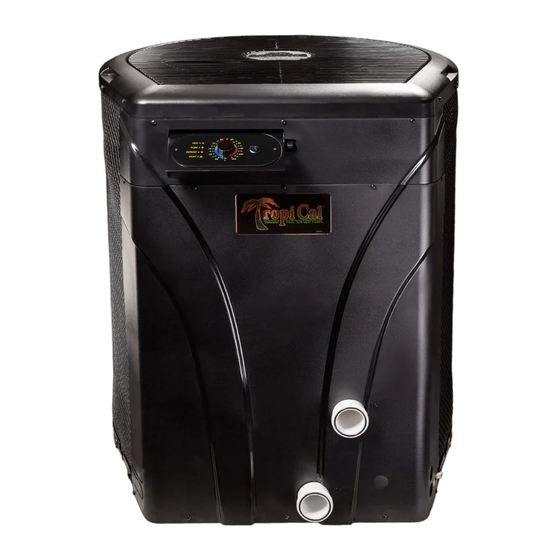
AquaCal
®
Installation Manual
®
WATER CHILLER
Five (Push) Button Display v2.xxx (HP11 control board)
Important
Read this document before operating / installing this product
For additional product manuals and operation / installation procedures, please visit www.AquaCal.com
LTM1110 REL C
- (project rel 8.00)
Advertisement
Table of Contents

Related Manuals for Aquacal HEATWAVE SUPERQUIET TropiCal TropiCool TC1000


Summary of Contents for Aquacal HEATWAVE SUPERQUIET TropiCal TropiCool TC1000
- Page 1 ® WATER CHILLER Five (Push) Button Display v2.xxx (HP11 control board) Important Read this document before operating / installing this product For additional product manuals and operation / installation procedures, please visit www.AquaCal.com LTM1110 REL C - (project rel 8.00)
-
Page 3: Table Of Contents
Table of Contents Contacting AquaCal AutoPilot, Inc. Safety 1 - Installation 1.1 Positioning Equipment 1.2 Electrical 1.2.A Electrical Requirements 1.2.B Incoming Power Access Holes 1.2.C Access Panels 1.2.D Verifying Transformer Setting (Select Units) 1.2.E Schematic Location 1.3 Plumbing 1.3.A Plumbing Requirements 1.3.B Plumbing Diagrams... - Page 4 2.5.B Available Accessories 2.5.C Cleaning Equipment After Installation 2.5.D Clearances 2.5.E Irrigation and Storm Run-Off 2.5.F Initial Cooling Recommendations 2.5.G Initial Heating Recommendations 2.5.H Saving Installer Settings to USB 2.5.I Use Installer Settings from USB 2.5.J Site Configuration Presets (Optional) 2.5.K Standards 2.5.L Schematics 2.5.M Winterizing...
-
Page 5: Contacting Aquacal Autopilot, Inc
Repair and service of heat pump must be performed by an authorized service center. Warranties may be voided if the equipment has been improperly installed, maintained or serviced. If service is deemed necessary, please contact AquaCal. SAFETY SIGNALS Throughout this document, safety signals have been placed where particular attention is required. - Page 6 Failure to heed the following may result in injury or death. WARNING Installation and repairs must be performed by a qualified technician. The heat pump contains refrigerant under pressure. Repairs to the refrigerant circuit must not be attempted by untrained and / or unqualified individuals. Service must be performed only by qualified HVAC technicians. Recover refrigerant before opening the system.
-
Page 7: Installation
1 - Installation Failure to heed the following will result in injury or death. DANGER Deactivate power while routing wiring to control board. RISK OF ELECTRICAL SHOCK FROM ENERGY STORED IN CAPACITORS - MODELS EQUIPPED WITH VARIABLE FREQUENCY COMPRESSOR DRIVES STORE ELECTRICITY EVEN AFTER THE POWER HAS BEEN DEACTIVATED AT THE POWER BREAKER. -
Page 8: Positioning Equipment
Heat Pumps require unobstructed airflow for proper operation. Heat Pumps should never be installed indoors or in a location where airflow is restricted. If an indoor installation is being considered, the installer and dealer are strongly urged to contact the AquaCal Application Department, or a local Professional Engineer prior to proceeding. -
Page 9: Electrical
Never mount power-disconnects directly to the heat pump. In sizing power wiring, be especially aware of up-sizing requirements necessary due to wiring distances. Always satisfy applicable codes and standards. AquaCal ® heat pumps are designed to use copper conductors, only. Do not use aluminum wire. - Page 10 Minimum and Maximum Operating Voltage The heat pump must operate within specified voltages. Failure to heed the following may result in damage to equipment. NOTICE Operating equipment under higher or lower voltage conditions may result in damage to your compressor, motors or other electrical components.
-
Page 11: B Incoming Power Access Holes
1.2.B Incoming Power Access Holes 1.2.C Access Panels Failure to heed the following will result in injury or death. DANGER Deactivate power while routing wiring to control board. RISK OF ELECTRICAL SHOCK FROM ENERGY STORED IN CAPACITORS - MODELS EQUIPPED WITH VARIABLE FREQUENCY COMPRESSOR DRIVES STORE ELECTRICITY EVEN AFTER THE POWER HAS BEEN DEACTIVATED AT THE POWER BREAKER. -
Page 12: D Verifying Transformer Setting (Select Units)
1.2.D Verifying Transformer Setting (Select Units) Transformer voltage must be confirmed and set correctly depending on the measured voltage found on the site. Incorrect settings may cause heat pump damage. The following procedure will allow the installer to set the heat pump's transformer for the appropriate site voltage. Failure to heed the following will result in injury or death. -
Page 13: Plumbing
Plumbing diagrams are provided in this section as a planning guide to the sequence of equipment, valves, and fittings. The basic plumbing configurations for typical installations are shown. If the installation does not closely follow any of the supplied plumbing diagrams, AquaCal ® Technical Support is available for installation advice and guidance. - Page 14 Heat Pump with water flows greater than the maximum listed flow rate See "Water Flow Rates" on page 13. Heat Pump with Spillover Spa (One filter Pump) Page - 10...
- Page 15 Heat Pump with Spillover Spa (Two filter Pumps) Heat Pump with Solar Panels in Plumbing Circuit Heat Pump with Gas Heater backup Page - 11...
-
Page 16: C Maintaining Ability To Winterize
1.3.D Water Connections to Heat Pump Heat Pump union sizes are specified on diagrams. Connections to site plumbing are made via PVC solvent cement to the female slip socket of the plumbing unions. Plumbing unions are available from AquaCal ® Page - 12... -
Page 17: E In-Line Chlorine Feeders
1.3.E In-Line Chlorine Feeders Place in-line chlorinators downstream from the heat pump and as low in elevation as possible. If an erosion type feeder is used, it is recommended that a Hartford Loop be installed to protect internal heat pump components. A Hartford Loop is not required when using a Salt Chlorine Generator. - Page 18 FLOW RATES MODEL HEAT EXCHANGER TYPE MINIMUM MAXIMUM ® T135* Titanium ThermoLink 30 GPM (113.6 L/min) 70 GPM (265 L/min) ® T135R* Titanium ThermoLink 30 GPM (113.6 L/min) 70 GPM (265 L/min) TC500 Titanium Tube-in-Tube 20 GPM (75.7 L/min) 45 GPM (170 L/min) ®...
-
Page 19: G Heat Pump Bypass Requirements
1.3.G Heat Pump Bypass Requirements The heat pump requires a certain water flow rate in order to operate properly. A bypass can be used to regulate the flow to the Heat Pump. See "Water Flow Rates" on page 13. Bypass Valve Kit (# STK0135) When high flow rates are outside recommended specifications, please use this kit or an alternative bypass valve system. -
Page 20: B Setting Date And Time Format
Enter "System" menus, then proceed PRESS MENU USE ARROWS TO PRESS "ENTER" BUTTON "SYSTEM" USE ARROWS TO MENU PRESS ENTER, ITEM TO USE ARROWS TO "TIME / DATE" CHANGE WILL BLINK CHANGE ENTER TO SAVE MENU TO EXIT, PRESS & HOLD TO STATUS 1.4.B Setting Date and Time Format The heat pump's date and time format can be customized. -
Page 21: C Selecting Celsius Or Fahrenheit
Customize Date The date can be displayed as Day-Month-Year (the default is Month-Day-Year). Enter "System" menus, then proceed PRESS MENU USE ARROWS TO PRESS "ENTER" BUTTON "SYSTEM" USE ARROWS TO MENU ENTER TO EDIT USE ARROWS "DATE FORMAT" TO CHANGE ENTER TO SAVE MENU TO EXIT, PRESS &... -
Page 22: D Activate Heat Mode, Cool Mode, Auto Mode, Or Deactivate Equipment
1.4.D Activate HEAT Mode, COOL Mode, AUTO Mode, or Deactivate Equipment Press "Mode / Enter" button until the desired mode is displayed. "HEAT" mode - After the fan and compressor start, the red "Heating" light will activate. "COOL" mode - After the fan and compressor start, the blue "Cooling" light will activate. "AUTO"... -
Page 23: E Set A Desired Temperature (Setpoint) For The Heat Pump To Activate
1.4.E Set a desired temperature (setpoint) for the Heat Pump to activate Press the up or down arrow to set the desired temperature (setpoint) for the water. The heating indicator will illuminate when heating the water. The cooling indicator will illuminate when cooling the water. PLEASE NOTE: The maximum temperature the Heat Pump can be set to is 104°... -
Page 24: F Using Shortcuts
1.4.F Using Shortcuts The shortcuts menu provides quick access to model specific options and features. The following outlines some of these options. Service Mode This mode will deactivate the heat pump as well as all equipment connected to the heat pump. (See "... - Page 25 Turbo Boost (Variable Speed Heat Pumps Only) Upon demand, the heat pump's compressor can be set to maximum speed to heat or cool the water quickly. This is regardless of any previously set efficiency mode settings. The system will heat or cool the water with the compressor speed set to maximum. This will continue until the set temperature is reached.
-
Page 26: Optional Installations
Circulation Pumps Connect and control compatible circulation pumps to the heat pump. External Controllers To support a direct connection to an external controller, AquaCal® heat pumps are equipped with removable terminal blocks on the control board. Using Multiple Heat Pumps Up to 16 heat pumps can be connected and controlled from a primary heat pump. -
Page 27: Optional Programming
1.6 Optional Programming IN THIS SECTION: 1.6.A Freeze Protection 1.6.B Setting Entry Code Option 1.6.C Disabling Entry Code Option 1.6.D Schedule and Program Modes 1.6.A Freeze Protection Failure to heed the following may result in damage to equipment. NOTICE By default (from the factory) the Freeze Protection feature WILL NOT protect the heat pump. The Freeze Protection feature is dependent on equipment controlled by properly configured groups. - Page 28 PRESS "MENU" USE ARROWS TO PRESS "ENTER" BUTTON "GROUPS" USE ARROWS TO PRESS "ENTER" ARROWS TO "FREEZE PROTECT ENABLED" GROUP TO EDIT TO EDIT PRESS "ENTER" USE ARROWS TO MENU TO EXIT, PRESS TO EDIT CHANGE TO "ON" & HOLD TO STATUS Adjusting Freeze Protection Options Failure to heed the following may result in damage to equipment.
-
Page 29: B Setting Entry Code Option
USE ARROWS TO PRESS "ENTER" USE ARROWS TO MENU "ADVANCED" "FREEZE PROTECT" PRESS "ENTER" ENTER & ARROWS TO ENTER & ARROWS TO "PROTECT ON SETPOINT" "PROTECT OFF SETPOINT" TO EDIT ENTER & ARROWS TO ENTER & ARROWS TO MENU TO EXIT, PRESS "CYCLE TIME"... -
Page 30: C Disabling Entry Code Option
ENTER TO SAVE USE ARROWS TO MENU ENTER TO EDIT "USER CODE ENABLED" USE ARROWS TO ENTER TO SAVE MENU TO EXIT, PRESS CHANGE & HOLD TO STATUS 1.6.C Disabling Entry Code Option PLEASE NOTE - If an entry code has already been activated, the code must be entered before proceeding to disable. - Page 31 ENTER TO SAVE MENU TO EXIT, PRESS & HOLD TO STATUS Page - 27...
-
Page 32: D Schedule And Program Modes
1.6.D Schedule and Program Modes If the heat pump uses groups and schedules, the schedules can be deactivated temporarily as needed. Either globally through a schedule mode, or individually by setting a group's program mode. NOTE The standard (from the factory) heat pump does not have a group or schedule. These can be created as needed depending on if a heat pump option has been utilized. - Page 33 Set Schedule Mode to "AUTO" Enter "Shortcuts" menus, then proceed PRESS MENU USE ARROWS TO PRESS "ENTER" BUTTON "SHORTCUTS" ARROWS TO ENTER TO EDIT ARROWS TO "SCHEDULE MODE" "AUTO" ENTER TO SAVE MENU TO EXIT, PRESS & HOLD TO STATUS Set Schedule Mode to "AWAY"...
- Page 34 Set Schedule Mode to "OFF" Enter "Shortcuts" menus, then proceed PRESS MENU USE ARROWS TO PRESS "ENTER" BUTTON "SHORTCUTS" ARROWS TO ENTER TO EDIT ARROWS TO "SCHEDULE MODE" "OFF" ENTER TO SAVE MENU TO EXIT, PRESS & HOLD TO STATUS Set Group Programs to "ON"...
- Page 35 ENTER TO EDIT ARROWS TO ENTER TO SAVE "ON" MENU TO EXIT, PRESS & HOLD TO STATUS Set Group Programs to "PAUSED" In the following example, a "Pool" group's set of scheduled programs will be paused. This will continue until the programs are set back to "ON". Enter "Schedules"...
- Page 36 Set Group Programs to "OFF" In the following example, a "Pool" group's set of scheduled programs will be set from "ON" to "OFF". The schedules will not resume until the programs are set back to "ON". Enter "Schedules" menus, then proceed PRESS MENU USE ARROWS TO PRESS "ENTER"...
-
Page 37: Appendix
2 - Appendix IN THIS SECTION: 2.1 Service Mode 2.2 Service Help 2.3 Adjustments 2.3.A Adjusting Water Flow Using ΔT (Delta-T) 2.3.B Adjusting Water Pressure Switch (Select Units) 2.3.C Configure Variable Speed Compressors (Select Units) 2.3.D Three-Phase Adjustment 2.4 Defaults 2.4.A Equipment Parameters 2.4.B Factory Reset 2.4.C Menu Trees... -
Page 38: Service Help
Failure to heed the following may result in minor or moderate injury. CAUTION Servicing of this equipment by anyone other than a qualified technician can result in a safety hazard. Ordering Parts - https://www.aquacal.com/looking-for-a-part/ Sizing Equipment - https://sizing.aquacal.com/ 2.3 Adjustments... -
Page 39: A Adjusting Water Flow Using Δt (Delta-T)
IN THIS SECTION: 2.3.A Adjusting Water Flow Using ΔT (Delta-T) 2.3.B Adjusting Water Pressure Switch (Select Units) 2.3.C Configure Variable Speed Compressors (Select Units) 2.3.D Three-Phase Adjustment 2.3.A Adjusting Water Flow Using ΔT (Delta-T) The Delta-T is the temperature difference between the water temperatures entering and leaving the heat pump. - Page 40 Table 1 - Temperature Chart PLEASE NOTE - Temperature differences are based on pool water temperatures of 69° to 75° F. (20.5° to 23.8° C) For water temperatures outside this range, contact AquaCal ® . See "Contacting AquaCal AutoPilot, Inc." on page 1.
-
Page 41: B Adjusting Water Pressure Switch (Select Units)
2.3.B Adjusting Water Pressure Switch (Select Units) Adjust the water pressure switch when heat pump attempts to operate without water flow. Before attempting any adjustments confirm the following : The filter is clean. Filter pump is operating. The valves are set to direct the appropriate amount of water through the heat pump. -
Page 42: C Configure Variable Speed Compressors (Select Units)
Therefore a water flow switch must be used in place of a water pressure switch to determine if incoming water is being sent to the heat pump. 9. If the heat pump continues to operate without water flow, contact AquaCal ®... - Page 43 USE ARROWS TO MENU ENTER TO EDIT USE ARROWS TO "TURBO BOOST" CHANGE ENTER TO SAVE MENU TO EXIT, PRESS & HOLD TO STATUS Set Efficiency Mode to 24 Hour Enter "Advanced" menus, then proceed PRESS MENU USE ARROWS TO PRESS "ENTER"...
- Page 44 PRESS MENU USE ARROWS TO PRESS "ENTER" BUTTON "SYSTEM" USE ARROWS TO PRESS "ENTER" USE ARROWS TO MENU "ADVANCED" "EFFICIENCY MODE" ENTER TO EDIT USE ARROWS TO ENTER TO SAVE CHANGE TO "FILTRATION" MENU TO EXIT, PRESS & HOLD TO STATUS Page - 40...
-
Page 45: D Three-Phase Adjustment
Re-connect power and attempt to restart the unit. 3. When heat pump starts, disconnect power and verify off. Then confirm all line voltage connections are securely tightened. Reconnect power. If the heat pump does not start, contact AquaCal ® for further assistance. See "Contacting AquaCal AutoPilot, Inc."... -
Page 46: Defaults
2.4 Defaults IN THIS SECTION: 2.4.A Equipment Parameters 2.4.B Factory Reset 2.4.C Menu Trees 2.4.A Equipment Parameters This section describes all the possible parameters for equipment that can be connected to the heat pump. Pumps Parameter Description A set of names are provided for easy identification of the Name circulation pump. - Page 47 2.4.B Factory Reset A factory reset of all settings can be performed if needed. This will reset all settings to factory defaults. PLEASE NOTE: This action will wipe all previously set configurations such as external controller settings, optional device settings, groups, equipment, schedules, and site specific settings and return the heat pump to its default firmware settings from the factory.
- Page 48 2.4.C Menu Trees Page - 44...
- Page 49 Page - 45...
-
Page 50: Supplemental
Using External Controllers, Installing expansion boards, Connecting relays and actuators, using installation presets, and setting up groups and schedules. 2.5.B Available Accessories Accessories may be purchased through an authorized dealer of AquaCal ® products. Bypass Valve Kit (# STK0135) When high flow rates are outside recommended specifications, please use this kit or an alternative bypass valve system. - Page 51 A higher elevation of the water can cause a false signal to the heat pump; indicating water is flowing through the heat pump when it isn't. Liquid Blankets An invisible liquid heat barrier designed to retain heat and extend the swimming season. AquaCal ® recommends Lo-Chlor ®...
-
Page 52: C Cleaning Equipment After Installation
® PoolSync WI-FI Controller (ECP0343) This kit will add WiFi control capabilities to the heat pump. Contact installing dealer to order this product. Temperature Port Kit (# STK0096) This port can be used to adjust water flow using Delta-T. The kit comes with port, installation components, and a temperature probe. -
Page 53: D Clearances
Table 3 - Polishing Agents • The trademarks used in approved polishing agents are the property of their owners and are not related to AquaCal ® 2.5.D Clearances Proper air circulation is required for the heat pump to operate efficiently. The following diagrams show the minimum clearances required for the proper operation of the heat pump. -
Page 54: E Irrigation And Storm Run-Off
(Overhead Clearance) (Top View) 2.5.E Irrigation and Storm Run-Off Irrigation water may damage heat pump components. Direct irrigation water away from the heat pump. The heat pump will withstand normal rainfall. Do not allow a roof slope to direct rainwater onto the heat pump. Have a gutter installed on the roof edge to direct this water away from the heat pump. -
Page 55: G Initial Heating Recommendations
2.5.G Initial Heating Recommendations The following recommendations will reduce the amount of time required to heat a pool. If unsure of equipment heating capability, review equipment data plate. See "Identifying Model Specifications" on page 60. NOTE Using a pool blanket or liquid blanket can allow the water to retain heat and have quicker heating times. -
Page 56: I Use Installer Settings From Usb
PRESS MENU USE ARROWS TO PRESS "ENTER" BUTTON "SYSTEM" USE ARROWS TO PRESS "ENTER" USE ARROWS TO MENU "ADVANCED" "SAVE SETUP TO USB" PRESS "ENTER" DISPLAY WILL SHOW MENU TO EXIT, PRESS "SAVING...", THEN "DONE" & HOLD TO STATUS 7. Deactivate power to heat pump. 8. - Page 57 Failure to heed the following will result in injury or death. DANGER Deactivate power while routing wiring to control board. RISK OF ELECTRICAL SHOCK FROM ENERGY STORED IN CAPACITORS - MODELS EQUIPPED WITH VARIABLE FREQUENCY COMPRESSOR DRIVES STORE ELECTRICITY EVEN AFTER THE POWER HAS BEEN DEACTIVATED AT THE POWER BREAKER.
-
Page 58: J Site Configuration Presets (Optional)
7. After heat pump has successfully loaded file and restarted, deactivate heat pump at power breaker. 8. Wait two minutes for capacitors to discharge before proceeding. 9. Remove thumb drive. 10. Reinstall heat pump's access panel. 2.5.J Site Configuration Presets (Optional) A list of site configurations (presets) can be used to easily configure equipment directly connected to the heat pump. - Page 59 Select the appropriate preset for the site conditions. NOTE Variable speed circulation pump presets will not show on this document. Look for the "Options Manual (Circulation Pumps)" for those options. See https://www.aquacal.com/heatpump-manuals/. PRESET OPTIONS: Pool / Spa, No Pump Pool Only, No Pump...
-
Page 60: K Standards
2.5.L Schematics Some schematics have been provided in the appendix of this manual. PLEASE NOTE: Specifications are subject to change without notice. Schematics are available by calling AquaCal ® Customer Support. See "Contacting AquaCal AutoPilot, Inc." on page 1. Please have the complete model and serial number available. -
Page 61: M Winterizing
2.5.M Winterizing Failure to properly winterize the heat pump as needed may result in serious equipment damage. Failure to heed the following will result in injury or death. DANGER Deactivate power while routing wiring to control board. RISK OF ELECTRICAL SHOCK FROM ENERGY STORED IN CAPACITORS - MODELS EQUIPPED WITH VARIABLE FREQUENCY COMPRESSOR DRIVES STORE ELECTRICITY EVEN AFTER THE POWER HAS BEEN DEACTIVATED AT THE POWER BREAKER. - Page 62 ® Titanium ThermoLink Exchanger (with no Drain) 1. Disconnect the plumbing to the heat pump at connection unions (removal is counter- No Drain clockwise). 2. Allow water to drain completely from the heat pump. Expect to see a lot of water drain out at first, and then a small amount to continue to drain out over a long period.
-
Page 63: System Information
2.6 System Information IN THIS SECTION: 2.6.A Dimensions 2.6.B Identifying Model Specifications 2.6.C Viewing System Information 2.6.D Weights 2.6.A Dimensions ® TropiCal T090, T091, T115, T116, T135. ® HeatWave SuperQuiet SQ120R, SQ125, T135R SQ145, SQ166R and SQ225 ® TropiCool TC1500 ®... -
Page 64: B Identifying Model Specifications
2.6.B Identifying Model Specifications 1. Find Data Plate - The data plate is usually posted on the Data Plate Example side of the equipment or the inside of the heat pump's access plate. 2. Find the model number on the data plate. The first letters and numbers indicate the model type. - Page 65 USE ARROWS TO MENU PRESS ENTER TO VIEW USE ARROWS TO VIEW "UNIT SERIAL NUMBER" "INFORMATION" USE ARROWS TO VIEW USE ARROWS TO VIEW MENU TO EXIT, PRESS "UNIT MODEL NUMBER" "FIRMWARE VERSION" & HOLD TO STATUS Page - 61...
-
Page 66: D Weights
2.6.D Weights NOTE: Specifications subject to change. Model Type Model Number Install Weight 180 Pounds ® TropiCal T035 (81.6 kg) 180 Pounds ® TropiCal T055 (81.6 kg) 200 Pounds ® T075 TropiCal (90.7 kg) 255 Pounds ® TropiCal T090 (115.7 kg) 255 Pounds ®... - Page 67 Page - 63...
-
Page 68: Troubleshooting
3 - Troubleshooting Failure to heed the following will result in injury or death. DANGER Deactivate power while routing wiring to control board. RISK OF ELECTRICAL SHOCK FROM ENERGY STORED IN CAPACITORS - MODELS EQUIPPED WITH VARIABLE FREQUENCY COMPRESSOR DRIVES STORE ELECTRICITY EVEN AFTER THE POWER HAS BEEN DEACTIVATED AT THE POWER BREAKER. - Page 69 IN THIS SECTION: Fault Codes AQUASTAR VS PUMP FAULT DEFROST1 SENSOR OPEN or DEFROST2 SENSOR OPEN DEFROST1 SENSOR SHORT or DEFROST2 SENSOR SHORT ERROR AT PRIMARY UNIT HAYWARD VS PUMP FAULT HIGH PRESSURE FAULT HIGH WATER TEMP HP5 SYSTEM LOCKOUT HPC TEMP SYSTEM LOCKOUT JANDY VS PUMP FAULT LOW PRESSURE FAULT...
-
Page 70: Fault Codes
A fault code indicates a specific issue or condition that will require action before the equipment can resume operating. Please perform the following troubleshooting. If the issue reoccurs, please contact AquaCal. See "Contacting AquaCal AutoPilot, Inc." on page 1. AQUASTAR VS PUMP FAULT ISSUE The heat pump has either lost communication with a connected Aquastar circulation pump. -
Page 71: Hayward Vs Pump Fault
See "Adjusting Water Flow Using ΔT (Delta-T)" on page 35. Cool Only Units Determine if there is a proper air circulation around the equipment. 1. Check for proper fan operation. If the fan is not operating, contact AquaCal ® Technical Support. -
Page 72: High Water Temp
HIGH WATER TEMP ISSUE Incoming water temperature has exceeded 108° F (42° C) and the unit has been deactivated. The heat pump will not operate until the incoming water temperature drops to 100° F (38° C) or lower. RESOLUTION 1. Determine if a gas heater is sending water directly to the heat pump. This situation would need to be corrected before continuing. -
Page 73: Low Pressure Fault
ISSUE The refrigerant system’s low-pressure switch is showing as open. RESOLUTION Heat Only Units 1. Check for proper fan operation. If the fan is not operating, contact AquaCal ® Technical Support. 2. Check for obstructed airflow around the heat pump. -
Page 74: Multiple Primary Fault
2. If this does not resolve the issue, a qualified technician should verify the connection between the control board and the display (loose or disconnected cable, crimps in the cable, etc.). 3. If the issue reoccurs, please contact AquaCal. See "Contacting AquaCal AutoPilot, Inc." on page 1. PENTAIR VS PUMP FAULT ISSUE The heat pump has either lost communication with a connected Pentair water pump. -
Page 75: Smart Comm Fault
SMART COMM FAULT ISSUE Heat Pump is not receiving a signal from an external controller using a smart connection point. RESOLUTION 1. Confirm a smart external controller is being used. If not, set external controller mode to "none" instead of "SMART". 2. -
Page 76: Water Temp1 Sensor Short Or Water Temp1 Sensor Open
WATER TEMP1 SENSOR SHORT WATER TEMP1 SENSOR OPEN ISSUE Open or shorted water sensor. RESOLUTION A qualified technician should replace the water sensor. Until the sensor is replaced, the setpoint is limited to 96° F (35.5° C) WATER TEMP2 SENSOR SHORT WATER TEMP2 SENSOR OPEN ISSUE Open or shorted water sensor. -
Page 77: Issues And Resolutions
3.2 Issues and Resolutions Please perform the following troubleshooting. For further assistance, please contact AquaCal. See "Contacting AquaCal AutoPilot, Inc." on page 1. Blank Display ISSUE The Heat Pump may have an incoming power problem. RESOLUTION Confirm electrical power is being supplied to the heat pump from electrical disconnect(s). -
Page 78: Displays "Defrosting
Displays Defrosting Displays "DEFROSTING" ISSUE The heat pump has sensed the coil is icing up. See "Ice Forming on the Heat Pump" on page 79. No action is required. RESOLUTION Heat Only Units - Passive Defrost When ice starts to form on the coil, the compressor will stop operating while the fan continues to operate. -
Page 79: Displays "No System Firmware
"NO SYSTEM FIRMWARE" Displays ISSUE The heat pump has encountered a software error. RESOLUTION ® 1. If heat pump is using a PoolSync , confirm the device is connecting to the internet. It will ® automatically attempt to load firmware on the heat pump. See PoolSync manual for specifics. -
Page 80: Displays "Unit Model Number
The heat pump has encountered a software error. RESOLUTION The model number and serial number will need to be re-entered into the system. The system will then operate as normal. If the issue reoccurs, please contact AquaCal ® Technical Support. Heat Pump Not Running ISSUE The heat pump will not run. -
Page 81: Heat Pump Won't Shut Off
Heat Pump Won’t Shut Off ISSUE The heat pump will not deactivate. RESOLUTION PLEASE NOTE When the heat pump is set to off, the display will show the current water temperature or no water flow indicator. 1. Confirm the correct mode has been set on the heat pump. 2. -
Page 82: Heat Pump Is Running, Not Cooling
Heat Pump Is Running, Not Cooling ISSUE The heat pump is running. But the water is not cooling. RESOLUTION 1. If the heat pump is using an external controller, confirm the heat pump is programmed properly to allow for cooling. 2. -
Page 83: Ice Forming On The Heat Pump
Ice Forming on the Heat Pump Ice Forming on the Heat Pump ISSUE When conditions are too cold for proper operation, the heat pump will enter a defrost mode. This prevents ice from building up on the evaporator coil. RESOLUTION Heat Only Units: The heat pump may develop a fine layer of white frost on the outside coil before entering the defrost mode. -
Page 84: Pool / Spa" Button Isn't Working
"Pool / Spa" Button Isn't Working ISSUE The "Pool / Spa" button is disabled if the following devices have been configured on the heat pump. A 2-wire external controller. A 3-wire external controller. A "SMART" external controller. An external flow switch. RESOLUTION If not used to operate the heat pump, deactivate the external control device. -
Page 85: Water Coming From Heat Pump
Water Coming From Heat Pump ISSUE The water may be normal condensation produced as a by-product of the heat pump's refrigeration process. The heat pump can produce up to 8 to 10 gallons (30 to 38 liters) of condensation per hour depending on the humidity of the ambient air.
Need help?
Do you have a question about the HEATWAVE SUPERQUIET TropiCal TropiCool TC1000 and is the answer not in the manual?
Questions and answers