Table of Contents
Advertisement
SERVICE
REFRIGERATOR
REFRIGERATOR
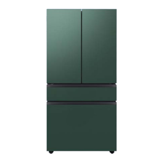
FRENCH DOOR REFRIGERATOR
MODEL NAME : RF23BB*
MODEL CODE : RF23BB8** (4D C/D)
RF29BB8** (4D F/S)
RF24BB6** (3D C/D)
RF30BB6** (3D F/S)
Manual
CONTENTS
1. PRODUCT INFORMATION ·······································5
2. PRODUCT SPECIFICATIONS ··································· 7
3. FUNCTIONS & FEATURES ····································· 19
4. DISASSEMBLY AND REASSEMBLY ····················26
5. CHECK THE INSTALLATION STATUS ···················75
6. SELF DIAGNOSIS & TROUBLE SHOOTING ······ 113
7. PCB DIAGRAM ······················································134
8. WIRING DIAGRAM ···············································138
9. BLOCK DIAGRAM ················································ 140
10. REFERENCE INFORMATION ···························· 141
Advertisement
Table of Contents

Related Manuals for Samsung RF30B Series


Summary of Contents for Samsung RF30B Series
- Page 1 REFRIGERATOR FRENCH DOOR REFRIGERATOR MODEL NAME : RF23BB* MODEL CODE : RF23BB8** (4D C/D) RF29BB8** (4D F/S) RF24BB6** (3D C/D) RF30BB6** (3D F/S) SERVICE Manual REFRIGERATOR CONTENTS 1. PRODUCT INFORMATION ·······································5 2. PRODUCT SPECIFICATIONS ··································· 7 3. FUNCTIONS & FEATURES ····································· 19 4.
- Page 2 "look and feel" and arrangement of such Content, contained in this manual is owned, controlled or licensed by or to Samsung, and is protected by trade dress, copyright, patent and trademark laws, and various other intellectual property rights and unfair competition laws.
- Page 3 SAMSUNG ELECTRONIC, INC. Technical Service Guide Copyright ©2020 rights reserved. This service guide may not be reproduced in whole or as a part in any form whatsoever without the written permission of the SAMSUNG ELECTRONICS Company.
-
Page 4: Table Of Contents
Contents 1. Product Information ..........................5 1-1) Safety Warnings ..................................5 2. Product Specifications ...........................7 2-1) Introduction of Main Function ..............................7 2-2) Model Specification ................................9 2-3) Electric Parts Specification ..............................13 2-4) Dimensions of Refrigerator ..............................14 2-5) Refrigerant Route in Refrigeration cycle ..........................15 2-6) Principle Of Freezer ................................16 2-7) Operation theory of refrigeration cycle components ..................... - Page 5 Contents 4-37) COMPRESSOR ..................................70 4-38) Main PCB and Inverter PCB ..............................72 4-39) F-Hub LCD ..................................73 5. Check the installation status ......................75 5-1) Function for failure diagnosis (RF24BB6**, RF30BB6** Inner Display apply models) ..........75 5-1-1. Test mode (manual operation / manual defrost function) ......................75 5-1) Function for failure diagnosis (RF23BB8**, RF29BB8** Inner Display apply models) ..........80 5-1-1.
-
Page 6: Product Information
This document cannot be used without Samsung's authorization. 1. PRODUCT INFORMATION 1-1) Safety Warnings Read all instructions before repairing the product and follow the instructionsin order to prevent danger or property damage. CAUTION/WARNING SYMBOLS DISPLAYED means "Prohibited". Indicates that a danger... - Page 7 This document cannot be used without Samsung's authorization. PRODUCT INFORMATION ※ Please let users know following warnings & cautions in detail. Warning & Caution Do not allow users to store Advice users not to store items on Advise users not to plug several top of the product.
-
Page 8: Product Specifications
This document cannot be used without Samsung's authorization. 2. PRODUCT SPECIFICATIONS 2-1) Introduction of Main Function ■ A newly developed SAMSUNG BMF refrigerator in 2022 has the following characteristics. Image Feature BESPOKE • Create a beautifully stylish and unique kitchen space with a customizable design. - Page 9 This document cannot be used without Samsung's authorization. Image Feature Metal Cooling • MainTain the optimal temperature inside the fridge, so food stays fresh, even if you frequently open and close the door. A Metal Cooling plate on the door and Flat Metal Duct retain the cold from the air and help to restore any heat loss quickly.
-
Page 10: 2-2) Model Specification
This document cannot be used without Samsung's authorization. PRODUCT SPECIFICATIONS 2-2) Model Specification Item Specification Models RF23BB89*** RF23BB86*** DRF36C400** RF23BB82*** RF29BB89*** RF29BB86*** RF29BB82*** Total 22.5 cu.ft 22.8 cu.ft 23 cu.ft 22.9 cu.ft 28.5 cu.ft 28.7 cu.ft 28.8 cu.ft Freezer Capacity... - Page 11 This document cannot be used without Samsung's authorization. PRODUCT SPECIFICATIONS Item Specification Models RF24BB69*** RF24BB66*** DRF36C300** RF24BB62*** RF30BB69*** RF30BB66*** RF30BB62*** Total 23.5 cu.ft 23.5 cu.ft 23.5 cu.ft 23.6 cu.ft 29.5 cu.ft 29.6 cu.ft 29.7 cu.ft Freezer 6..8 Capacity Refrigerator 16.7 16.7...
- Page 12 This document cannot be used without Samsung's authorization. PRODUCT SPECIFICATIONS Items Specification RF23B****** RF24B****** Model RF29B****** RF30B****** DRF36C400** DRF36C300** Cooling system Twin Cooling Energy Grade E-STAR, A+, EU E Model NF94R9151ATE01 NF94R9151ATE01 RF54M7151ANE01 RF54M7151ANE01 Compressor Starting type BLDC Oil Charge 200 ±...
- Page 13 This document cannot be used without Samsung's authorization. PRODUCT SPECIFICATIONS Items Specification Specification Model RF23BB8**** RF29BB8**** RF24BB6**** RF30BB6**** Temperature Model ON(℃) OFF(℃) ON(℃) OFF(℃) ON(℃) OFF(℃) ON(℃) OFF(℃) Selection -23℃ -21.5 -24.5 -21.5 -24.5 -21.5 -24.5 -21.5 -24.5 THERMISTOR (F-sensor) -19℃...
-
Page 14: 2-3) Electric Parts Specification
This document cannot be used without Samsung's authorization. PRODUCT SPECIFICATIONS 2-3) Electric Parts Specification Items Specification RF23B****** RF24B****** Model DRF36C400** DRF36C300** RF29B****** RF30B****** AC120V 230W AC120V 230W French AC120V 10W AC120V 12W Heater Ice water drain pipe #1 DC12V 2.3W DC12V 2.3W... -
Page 15: 2-4) Dimensions Of Refrigerator
This document cannot be used without Samsung's authorization. PRODUCT SPECIFICATIONS 2-4) Dimensions of Refrigerator Modle RF23BB8* RF29BB8* RF24BB6* RF30BB6* 28 6/8" 34 1/4" 28 6/8" 34 1/4" Depth "A" (730 mm) (868 mm) (730 mm) (868 mm) 35 6/8" (908 mm) Width "B"... -
Page 16: 2-5) Refrigerant Route In Refrigeration Cycle
This document cannot be used without Samsung's authorization. PRODUCT SPECIFICATIONS 2-5) Refrigerant Route in Refrigeration cycle 9. ASSY PIPE SUCTION PIPE HOT 4. PIPE HOT 5. DRYER 7. PIPE CAPILLARY 6. VALVE STEP 10. PIPE CONNECT -SUCTION 8. EVAPORATOR-REF 1. COMP 10. -
Page 17: 2-6) Principle Of Freezer
This document cannot be used without Samsung's authorization. PRODUCT SPECIFICATIONS 2-6) Principle Of Freezer EVAPORATOR -R EF PIPE CAPILLARY -R VALVE STEP EVAPORATOR -F RE PIPE CAPILLARY -F DRYER ASSY PIPE SUCTION COMPRESSOR PIPE HOT PIPE CONNECT -S UCTION PIPE CLUSTE- REAR... -
Page 18: 2-7) Operation Theory Of Refrigeration Cycle Components
This document cannot be used without Samsung's authorization. PRODUCT SPECIFICATIONS 2-7) Operation theory of refrigeration cycle components ■ Condenser 1) Role : A device which radiates heat to the outside (water/air) to make liquid state for the high temperature / high pressure gas refrigerant discharged from compressor. - Page 19 This document cannot be used without Samsung's authorization. PRODUCT SPECIFICATIONS ■ Dryer 1) Role : Absorb the moisture from the refrigerant that refrigeration cycle circulates and eliminate the foreign substance. 2) Structure : If even some moisture is included refrigerant is impossible to circulate by freezing the small capillary outlet, so silica gel or molecular sieve is (included and) sealed to absorb the internal moisture, and install a minute net to eliminate the foreign substance.
-
Page 20: Functions & Features
This document cannot be used without Samsung's authorization. 3. FUNCTIONS & FEATURES 3-1) Control Display (RF24B**, RF30B** Inner Display apply models) ❶ Explanation of Button operation 1. Tap any button (<, O, or >) to wake up the display. - This step may not apply to some models. - Page 21 This document cannot be used without Samsung's authorization. FUNCTIONS & FEATURES ❸ Setting the desired temperature or function • When the Fridge temperature indicator blinks, press the '<' key to set it as follows 7 °C → 6 °C → 5 °C → 4 °C → 3 °C → 2 °C → 1 °C →...
-
Page 22: 3-2) Digital Display (Rf23Bb8**, Rf29Bb8** Inner Display Apply Models)
This document cannot be used without Samsung's authorization. FUNCTIONS & FEATURES 3-2) Digital Display (RF23BB8**, RF29BB8** Inner Display apply models) ❶ Setting the desired temperature or function You can use the Fridge button to set the fridge temperature or to activate Power Cool. - Page 23 This document cannot be used without Samsung's authorization. FUNCTIONS & FEATURES You can also use the Freezer button to switch the temperature scale between Celsius ℉ ↔ ℃ and Fahrenheit. To switch the temperature scale, press and hold Freezer for 3 seconds to change the current temperature scale.
-
Page 24: 3-3) Smartthings
Visit the Google Play Store, Galaxy Apps, or Apple App Store and search for "SmartThings". Download and install the SmartThings app provided by Samsung Electronics to your smart device. • The SmartThings app is not available for some tablet and iPad and some smartphone. -
Page 25: 3-4) Using The Fridge Manager ( Family Hub )
This document cannot be used without Samsung's authorization. FUNCTIONS & FEATURES 3-4) Using the Fridge Manager ( FAMILY HUB ) ■ Fridge Manager To access Fridge Manager, swipe the home screen to the left, and them tap the Fridge Manager widget. - Page 26 This document cannot be used without Samsung's authorization. FUNCTIONS & FEATURES Also displayed is the Ice Off(ice making off) indicator at the top, center. When the indicator displays Ice Off, the refrigerator's ice maker is turned off. Turns the icemaker on and off. Tap and drag the button to turn on or off. Note that if the ice bucket is...
-
Page 27: Disassembly And Reassembly
This document cannot be used without Samsung's authorization. 4. DISASSEMBLY AND REASSEMBLY 4-1) Precaution Photograph Part Name Part Cod AMOUNT FILTER WATER-ASSY DA97-17376B LED LAMP TOP DA96-01119B LED LAMP FRE DA41-00676J LED LAMP (Flex Zone) DA41-00676J ■ Required Tools IMAGE... -
Page 28: 4-2) Assy Top Table
This document cannot be used without Samsung's authorization. DISASSEMBLY AND REASSEMBLY 4-2) Assy Top Table Part Name How To Do Descriptive Picture [Disassembly] 1. Remove 3 screw fixing Top Table Cover with the (+) screw driver and open. 2. Disconnect the housing connectors from the Assy Top Table. -
Page 29: 4-3) Fridge Door
This document cannot be used without Samsung's authorization. DISASSEMBLY AND REASSEMBLY 4-3) Fridge Door Part Name How To Do Descriptive Picture [Disassembly] 1. Remove the 3 screws fixing the Top Table and separate the Top Table. Refer to the previous explanation "Disassembly and Reassembly way for 3-2."... -
Page 30: 4-4) Flex Zone Door
This document cannot be used without Samsung's authorization. DISASSEMBLY AND REASSEMBLY 4-4) Flex Zone Door Part Name How To Do Descriptive Picture [Disassembly] 1. After opening the Flexzone door, lift the drawer box. Flex zone Door 2. Remove 2 hex head bolts from both sides with (Conv) a socket wrench(7/16"). -
Page 31: 4-5) Freezer Door
This document cannot be used without Samsung's authorization. DISASSEMBLY AND REASSEMBLY 4-5) Freezer Door Part Name How To Do Descriptive Picture [Disassembly] 1. After opening the Freezer door, lift drawer boxes. Remove upper box and also lower one. 2. Remove 4 hex head bolts from both side with a socket wrench(7/16"). -
Page 32: 4-6) Bespoke Panel Door - Freezer
This document cannot be used without Samsung's authorization. DISASSEMBLY AND REASSEMBLY 4-6) Bespoke panel door - Freezer Part Name How To Do Descriptive Picture [Disassembly] 1. Remove the 3 caps fixing the Cap Door. Bespoke Panel Door (Ref) 2. Lift up the Bespoke Panel Door and disassemble it. -
Page 33: 4-7) Bespoke Panel Door - Flex Zone, Freezer
This document cannot be used without Samsung's authorization. DISASSEMBLY AND REASSEMBLY 4-7) Bespoke panel door - Flex zone, Freezer Part Name How To Do Descriptive Picture [Disassembly] 1. Remove the 3 caps fixing the Cap Door. Bespoke Panel Door (Flex zone, 2. -
Page 34: 4-8) Flex Zone Door Switch
This document cannot be used without Samsung's authorization. DISASSEMBLY AND REASSEMBLY 4-8) Flex Zone Door Switch When disassembling, make sure the unit turned off. Part Name How To Do Descriptive Picture [Disassembly] 1. Push the hook with screw driver both side and pull out the door (Remove the door from REF) 2. -
Page 35: 4-9) Freezer Door Switch
This document cannot be used without Samsung's authorization. DISASSEMBLY AND REASSEMBLY 4-9) Freezer Door Switch When disassembling, make sure the unit turned off. Part Name How To Do Descriptive Picture [Disassembly] 1. Insert the small flat-heat screwdriver at side and use it as leverage. -
Page 36: 4-10) Refrigerator Door (Hinge Mid/Up)
This document cannot be used without Samsung's authorization. DISASSEMBLY AND REASSEMBLY 4-10) Refrigerator Door (Hinge Mid/Up) When disassembling, make sure the unit turned off. Part Name How To Do Descriptive Picture [Disassembly] 1. Remove the Grommet surrounding the Hinge Mid. -
Page 37: 4-11) French
This document cannot be used without Samsung's authorization. DISASSEMBLY AND REASSEMBLY 4-11) French Part Name How To Do Descriptive Picture [Disassembly] 1. Remove 2 screws fixing French with the (+) screw driver. 2. Lift the French upward to separate it. -
Page 38: 4-12) Gasket Door
This document cannot be used without Samsung's authorization. DISASSEMBLY AND REASSEMBLY 4-12) Gasket door Part Name How To Do Descriptive Picture [Disassembly] 1. Remove the 'French' before removing the 'Gasket Door' on the left side of the fridge. Refer to the previous explanation "Disassembly and Reassembly way for 4-11."... -
Page 39: 4-13) Internal Display
This document cannot be used without Samsung's authorization. DISASSEMBLY AND REASSEMBLY 4-13) Internal Display Part Name How To Do Descriptive Picture [Disassembly] 1. Remove the Inlay. 2. Push between RELECTOR and LINER with the (-) screw driver Internal Insert the (-) screw driver vertically to the end. -
Page 40: 4-14) Dispenser (Bsc)
This document cannot be used without Samsung's authorization. DISASSEMBLY AND REASSEMBLY 4-14) Dispenser (BSC) Part Name How To Do Descriptive Picture [Disassembly] 1. Lift and remove the Guard at the top of the Dispenser(BSC). 2. Remove the 2 screws fixing the Dispenser cover. - Page 41 This document cannot be used without Samsung's authorization. DISASSEMBLY AND REASSEMBLY Part Name How To Do Descriptive Picture 4. Remove the left/right side 2 screw and lift the STS cover. Dispenser (BSC) 5. Remove the Tube Fitting by pulling the water hose after pushing in the locking ring tab at the end of the Tube Fitting.
- Page 42 This document cannot be used without Samsung's authorization. DISASSEMBLY AND REASSEMBLY Part Name How To Do Descriptive Picture 7. Remove left/right side 2 screw and lift dispenser up to remove. Dispenser (BSC) Slide back from the front to remove.
-
Page 43: 4-15) Auto Fill
This document cannot be used without Samsung's authorization. DISASSEMBLY AND REASSEMBLY 4-15) Auto fill Part Name How To Do Descriptive Picture [Disassembly] 1. Lift and remove Guards at the top and right of the AUTO FILL. 2. Remove the 1 screw fixing the COVER. - Page 44 This document cannot be used without Samsung's authorization. DISASSEMBLY AND REASSEMBLY Part Name How To Do Descriptive Picture 5. Unsnap connectors of housing connectors at the top, Auto fill 6. Remove right side and bottom side screws. 7. Lift and remove THE CASE.
-
Page 45: 4-16) Fridge Internal Lamp
This document cannot be used without Samsung's authorization. DISASSEMBLY AND REASSEMBLY 4-16) Fridge Internal Lamp Part Name How To Do Descriptive Picture The decomposition assembly structure of the 2 Case Lamp is the same. Fridge Internal Lamp (upper) [Disassembly] 1. Insert a flat head screwdriver following the arrow symbol on the back side of COVER LAMP and pull back the hook. -
Page 46: 4-17) Freezer Internal Lamp
This document cannot be used without Samsung's authorization. DISASSEMBLY AND REASSEMBLY 4-17) Freezer Internal Lamp Part Name How To Do Descriptive Picture [Disassembly] 1. Pull out the drawer from Freezer 1) upper drawer 2) big lower drawer Upper drawer Big lower drawer 2. -
Page 47: 4-18) Shelf Fridge
This document cannot be used without Samsung's authorization. DISASSEMBLY AND REASSEMBLY 4-18) Shelf Fridge Part Name How To Do Descriptive Picture [Disassembly] Shelf Ref Up 1. Lift the shelf up slightly and pull it. Part Name How To Do Descriptive Picture [Disassembly] 1. -
Page 48: 4-19) Vegetable Shelf
This document cannot be used without Samsung's authorization. DISASSEMBLY AND REASSEMBLY 4-19) Vegetable Shelf Part Name How To Do Descriptive Picture [Disassembly] 1. Lift the shelf up slightly and pull it. 2. Pick up the front of the shelf. Vegetable Shelf 3. -
Page 49: 4-20) Assy Case Veg-Low
This document cannot be used without Samsung's authorization. DISASSEMBLY AND REASSEMBLY 4-20) Assy Case Veg-Low Part Name How To Do Descriptive Picture [Disassembly] 1. Grab the bottom handle of the ASSY CASE VEG-LOW. Assy Case 2. Pull it up and pull it out. -
Page 50: 4-21) Assy Guide Side
This document cannot be used without Samsung's authorization. DISASSEMBLY AND REASSEMBLY 4-21) Assy Guide Side Part Name How To Do Descriptive Picture [Disassembly] 1. Disassemble the ASSY CASE VEG-LOW and check the side of the GUIDE SIDE. 2. Press the front side of the GUIDE SIDE to disassemble the hook. -
Page 51: 4-22) Assy Water Filter
This document cannot be used without Samsung's authorization. DISASSEMBLY AND REASSEMBLY 4-22) Assy Water Filter Part Name How To Do Descriptive Picture [Disassembly] 1. Turn the water filter count-clockwise. (Refer to the picture) 2. Remove the water filter by pulling it. -
Page 52: 4-23) Case Water Filter
This document cannot be used without Samsung's authorization. DISASSEMBLY AND REASSEMBLY 4-23) Case Water Filter Part Name How To Do Descriptive Picture [Disassembly] 1. Remove 1 screw with the (+) screwdriver. 2. Remove the left and right latches of the filter case. - Page 53 This document cannot be used without Samsung's authorization. DISASSEMBLY AND REASSEMBLY Part Name How To Do Descriptive Picture 5. Remove three fixers securing the water tubes. Case Water Filter 6. Pull the Water blue hose out. 7. Lift and pull the Case Water Filter out.
-
Page 54: 4-24) Angle Shelf
This document cannot be used without Samsung's authorization. DISASSEMBLY AND REASSEMBLY 4-24) Angle Shelf Part Name How To Do Descriptive Picture [Disassembly] 1. First remove all shelves, filter and boxes. Angle Shelf 2. Remove screw 2EA. 3. Pull out at an angle upward. -
Page 55: 4-25) Ref Evap Cover
This document cannot be used without Samsung's authorization. DISASSEMBLY AND REASSEMBLY 4-25) REF Evap Cover Part Name How To Do Descriptive Picture [Disassembly] 1. Remove a screw and Case Water Filter before disassembling REF Evap Cover. 2. Move disassembled W/Filter to left side of the rail. - Page 56 This document cannot be used without Samsung's authorization. DISASSEMBLY AND REASSEMBLY Part Name How To Do Descriptive Picture Fan(White) 5. Disconnect all wires from Cabinet housing. Sensor (Yellow) 6. Untie all wires from each fixing hook. 7. Unscrew 7 screws and disassemble the Rear Cover.
-
Page 57: 4-26) Fridge Evaporator
This document cannot be used without Samsung's authorization. DISASSEMBLY AND REASSEMBLY 4-26) Fridge Evaporator Part Name How To Do Descriptive Picture [Disassembly] Refer Ref Evap Cover page 1. Remove all the shelves and drawers. 2. Pull the bottom part of the EVAP Cover forward to separate it. -
Page 58: 4-27) Ice Bucket
This document cannot be used without Samsung's authorization. DISASSEMBLY AND REASSEMBLY 4-27) Ice Bucket Part Name How To Do Descriptive Picture [Disassembly] 1. Open the left freezer door. Ice Bucket 2. Push the cover back. 3. Lift up the Ice bucket and remove it. -
Page 59: 4-28) Wine Rack & Shelf Slide
This document cannot be used without Samsung's authorization. DISASSEMBLY AND REASSEMBLY 4-28) Wine Rack & Shelf Slide Part Name How To Do Descriptive Picture [Disassembly] RACK WINE 1. Lift the shelf up slightly and pull it. Part Name How To Do... -
Page 60: 4-29) Assy Case Convertible
This document cannot be used without Samsung's authorization. DISASSEMBLY AND REASSEMBLY 4-29) Assy Case Convertible Part Name How To Do Descriptive Picture [Disassembly] 1. Pull out the door to the maximum. Assy Case 2. Pull it up and pull it out. -
Page 61: 4-30) Tray Fre Up
This document cannot be used without Samsung's authorization. DISASSEMBLY AND REASSEMBLY 4-30) Tray Fre Up Part Name How To Do Descriptive Picture [Disassembly] 1. Pull out the door to the maximum. Tray Fre Up 2. Move COVER to a position that does not get STOPPER. -
Page 62: 4-31) Tray Drawer
This document cannot be used without Samsung's authorization. DISASSEMBLY AND REASSEMBLY 4-31) Tray Drawer Part Name How To Do Descriptive Picture [Disassembly] 1. Remove the TRAY FRE UP. Tray Drawer 2. Pull it up and pull it out. 3. Lift it up and disassemble it. -
Page 63: 4-32) Assy Ice Maker
This document cannot be used without Samsung's authorization. DISASSEMBLY AND REASSEMBLY 4-32) Assy Ice Maker Part Name How To Do Descriptive Picture [Disassembly] 1. Release 2 fixed SCREW points. 2. Separate the HOUSING connected to the upper part. Assy Ice Maker 3. - Page 64 This document cannot be used without Samsung's authorization. DISASSEMBLY AND REASSEMBLY Part Name How To Do Descriptive Picture 5. (When the CUBE ICE is replaced) Press the motor fixing RIB and pull the motor out. Assy Ice Maker 6. When the motor wire is removed, Nugget ice...
-
Page 65: 4-33) Fre Evap Cover
This document cannot be used without Samsung's authorization. DISASSEMBLY AND REASSEMBLY 4-33) FRE EVAP Cover Part Name How To Do Descriptive Picture [Disassembly] 1. Remove an Ice Maker first and then 2 screws from both sides of the EVAP Cover. - Page 66 This document cannot be used without Samsung's authorization. DISASSEMBLY AND REASSEMBLY Reassembly is reverse sequences of disassembly Part Name How To Do Descriptive Picture 5. Remove a fan motor or Damper Motor. Do not touch Fan blades. CAUTION 6. Remove the Insulation from Front Cover.
-
Page 67: 4-34) Freezer Evaporator
This document cannot be used without Samsung's authorization. DISASSEMBLY AND REASSEMBLY 4-34) Freezer Evaporator Part Name How To Do Descriptive Picture [Disassembly] Refer Ref Evap Cover page 1. Remove all the shelves and drawers. 2. Pull the bottom part of the EVAP Cover forward to separate it. -
Page 68: 4-35) Machine Compartment Motor Fan
This document cannot be used without Samsung's authorization. DISASSEMBLY AND REASSEMBLY 4-35) Machine Compartment Motor Fan Part Name How To Do Descriptive Picture [Disassembly] 1. Remove the 5 screws from the COMP Cover. 2. Separate the housing connector. MOTOR FAN 3. - Page 69 This document cannot be used without Samsung's authorization. DISASSEMBLY AND REASSEMBLY Part Name How To Do Descriptive Picture 5. Arrange pipe without damaging to pull Fan motor out. Damage on Pipe may occur Gas leakage. CAUTION MOTOR FAN 6. Pull out Fan motor.
-
Page 70: 4-36) Step Valve
This document cannot be used without Samsung's authorization. DISASSEMBLY AND REASSEMBLY 4-36) Step Valve Part Name How To Do Descriptive Picture [Disassembly] 1. Remove the 5 screws from the COMP Cover. 2. Remove the screw and pull the Step Valve forward to separate it. -
Page 71: 4-37) Compressor
This document cannot be used without Samsung's authorization. DISASSEMBLY AND REASSEMBLY 4-37) COMPRESSOR Part Name How To Do Descriptive Picture [Disassembly] Check Details on Step Valve page STEP 1~3 1. Remove Step valve. 2. Arrange Pipe and Pipe capillary to take out Compressor. - Page 72 This document cannot be used without Samsung's authorization. DISASSEMBLY AND REASSEMBLY Part Name How To Do Descriptive Picture 6. Remove Cover by using Driver through the Principal of the lever. COMPRESSOR 7. Disassemble Relay from Compressor. 8. Reassemble Relay and Cover on Compressor.
-
Page 73: 4-38) Main Pcb And Inverter Pcb
This document cannot be used without Samsung's authorization. DISASSEMBLY AND REASSEMBLY 4-38) Main PCB and Inverter PCB Part Name How To Do Descriptive Picture [Disassembly] 1. Pull the refrigerator forward to secure sufficient work space behind the refrigerator. MAIN PCB and Inverter PCB 2. -
Page 74: 4-39) F-Hub Lcd
This document cannot be used without Samsung's authorization. DISASSEMBLY AND REASSEMBLY 4-39) F-Hub LCD Part Name How To Do Descriptive Picture [Disassembly] 1. Remove the 3 caps fixing the Cap Door. Bespoke Panel (Family HUB) 2. Lift up the Bespoke Panel Door, Disconnet Housing and disassemble it. - Page 75 This document cannot be used without Samsung's authorization. DISASSEMBLY AND REASSEMBLY How To Do Descriptive Picture ① COVER DISPLAY REAR ② WIRE HARNESS Disassemble F-Hub component ① COVER DISPLAY REAR - Disassemble Hook 4 point. ② WIRE HARNESS ② ②...
-
Page 76: Check The Installation Status
This document cannot be used without Samsung's authorization. 5. CHECK THE INSTALLATION STATUS 5-1) Function for failure diagnosis (RF24BB6**, RF30BB6** Inner Display apply models) 5-1-1. Test mode (manual operation / manual defrost function) • Press the '<' and '>' buttons at the same time for at least 6 seconds. The Control Display will blink with an interval of 0.5 seconds. - Page 77 This document cannot be used without Samsung's authorization. CHECK THE INSTALLATION STATUS 1) TEST Mode Entering Enter the Engineer Mode ① ③ ② '<'+ '>' Key are pressed simultaneously for 6 seconds. The Control Display will start blinking with an interval of 0.5 seconds. At this point, you may take your fingers off both buttons and press the '>' button to enter the Engineer Mode.
- Page 78 This document cannot be used without Samsung's authorization. CHECK THE INSTALLATION STATUS 2) Forced Operating Function 2-1) If any key is pressed once in test mode, blinks "FF" on the display and it indicates the refrigerator has entered the manual operation1. At this moment, buzzer beeps as an alarm.
- Page 79 This document cannot be used without Samsung's authorization. CHECK THE INSTALLATION STATUS 2-3) When you press any key one more time at Manual Operation2 [FF r], "FF F" on the display and it indicates the refrigerator has entered the manual operation3. At this moment, buzzer beeps as an alarm.
- Page 80 This document cannot be used without Samsung's authorization. CHECK THE INSTALLATION STATUS 3) Forced Defrost 3-1) When you press any key one more time at Manual Operation4 [FF A], Fd lights up on the Display Panel. At this time, FR-Defrost will be performed at the same time.
-
Page 81: 5-1) Function For Failure Diagnosis (Rf23Bb8**, Rf29Bb8** Inner Display Apply Models)
This document cannot be used without Samsung's authorization. CHECK THE INSTALLATION STATUS 5-1) Function for failure diagnosis (RF23BB8**, RF29BB8** Inner Display apply models) 5-1-1. Test mode (manual operation / manual defrost function) • Press the Fridge and FlexZone buttons at the same time for at least 6 seconds. The Control Display will start blinking with an interval of 0.5 seconds. - Page 82 This document cannot be used without Samsung's authorization. CHECK THE INSTALLATION STATUS 1-1) If any key is pressed once in test mode, blinks "FF" on the display and it indicates the refrigerator has entered the manual operation. At this moment, buzzer beeps as an alarm.
- Page 83 This document cannot be used without Samsung's authorization. CHECK THE INSTALLATION STATUS 2-1) If manual operation is selected, compressor will run at once without 7 minutes delay in any mode. If the refrigerator is on the defrost cycle at the moment, defrost will end and manual operation will begin.(Be careful if manual operation...
- Page 84 This document cannot be used without Samsung's authorization. CHECK THE INSTALLATION STATUS 3) Forced Defrost 3-1) When you press any key one more time at Fridge off Forced Operation [FF A], Fd lights up on the Display Panel. At this time, the Forcd Operation stops immediately and FR-Defrost will be performed at the same time.
-
Page 85: Self-Diagnostic Function (Rf24Bb6**, Rf30Bb6** Inner Display Apply Models)
This document cannot be used without Samsung's authorization. CHECK THE INSTALLATION STATUS 5-1-2. Self-diagnostic function (RF24BB6**, RF30BB6** Inner Display apply models) 1) Self-diagnostic function in the Initial power ON 1-1) Micom operates self-diagnostic function to check the temperature sensor condition within 1 second when the refrigerator turned On initially. - Page 86 This document cannot be used without Samsung's authorization. CHECK THE INSTALLATION STATUS 2) Self-diagnostic function during normal operation Enter the Engineer Mode ① ③ ② ② '<'+ '>' Key are pressed simultaneously for 6 seconds. The Control Display will blink with 0.5 second interval for 4 seconds.
-
Page 87: Self-Diagnostic Function (Rf23Bb8**, Rf29Bb8** Inner Display Apply Models)
This document cannot be used without Samsung's authorization. CHECK THE INSTALLATION STATUS 5-1-2. Self-diagnostic function (RF23BB8**, RF29BB8** Inner Display apply models) 1) Self-diagnostic function in the Initial power ON 1-1) Micom operates self-diagnostic function to check the temperature sensor condition within 1 second when the refrigerator turned On initially. - Page 88 This document cannot be used without Samsung's authorization. CHECK THE INSTALLATION STATUS 2) Self-diagnostic function during normal operation ② If Fridge Key + FlexZone Key are pressed simultaneously For 10 seconds, the self-diagnosis function will be selected. 2-1) If Fridge Key + FlexZone Key are pressed simultaneously for 6 seconds during normal operation, the temperature setting display will operate for 4 seconds (ON/OFF 0.5sec each).If Fridge Key + FlexZone Key are pressed simultaneously...
- Page 89 This document cannot be used without Samsung's authorization. CHECK THE INSTALLATION STATUS * Self-diagnosis CHECK LIST Item Diagnostic method Location image The voltage of MAIN PCB CN20-"10" ↔ "12" Freezer Sensor : shall be between 4.5V~1.0V The voltage of MAIN PCB CN20-"9" ↔ "11"...
- Page 90 This document cannot be used without Samsung's authorization. CHECK THE INSTALLATION STATUS * Self-diagnosis CHECK LIST Item Diagnostic method Location image The voltage of MAIN PCB CN20-"16" ↔ "18" Freezer Fan Error : shall be between 7V~12V The voltage of MAIN PCB CN20-"15" ↔ "17"...
- Page 91 This document cannot be used without Samsung's authorization. CHECK THE INSTALLATION STATUS * Self-diagnosis CHECK LIST Item Diagnostic method Location image Actually, If there is not a problem, it is Main ↔ Panel desirable to replace Main and Panel PCB...
- Page 92 This document cannot be used without Samsung's authorization. CHECK THE INSTALLATION STATUS * Self-diagnosis CHECK LIST Item Diagnostic method Location image The Freezer compartment abnormal high-temperature indicator blinks Check if the door has been open for a long time or if hot food has been stored in the compartment.
- Page 93 This document cannot be used without Samsung's authorization. CHECK THE INSTALLATION STATUS * Self-diagnosis CHECK LIST Item Diagnostic method Location image Check the input voltage. AC 60V (Input Power AC110~127V) Comp low voltage Error AC 106V (Input Power AC 220~240V) Check PCB bottom side soldering state.
-
Page 94: Display Function Of Load Condition (Rf24Bb6**, Rf30Bb6** Inner Display Apply Models)
This document cannot be used without Samsung's authorization. CHECK THE INSTALLATION STATUS 5-1-3. Display function of Load condition (RF24BB6**, RF30BB6** Inner Display apply models) Enter the Engineer Mode ① ③ ② ' <' '>' Key are pressed simultaneously for 6 seconds. The Control Display will blink with 0.5 second interval for ①... - Page 95 This document cannot be used without Samsung's authorization. CHECK THE INSTALLATION STATUS 1) If the '<' and '>' button are pressed simultaneously for 6 seconds during normal operation, the temperature setting display of Fridge and freezer compartments will blink ALL ON/OFF with 0.5 for 4 seconds.
-
Page 96: Display Function Of Load Condition (Rf23Bb8**, Rf29Bb8** Inner Display Apply Models)
This document cannot be used without Samsung's authorization. CHECK THE INSTALLATION STATUS 5-1-3. Display function of Load condition (RF23BB8**, RF29BB8** Inner Display apply models) ① ② ① If Fridge Key and FlexZone Key are pressed simultaneously for 6 seconds, ALL ON/OFF will blink with 0.5interval for 4 seconds. - Page 97 This document cannot be used without Samsung's authorization. CHECK THE INSTALLATION STATUS R-10 R-10 ⓐ ⓐ ⓕ ⓑ ⓕ ⓑ ⓖ ⓖ CoolSelectZone CoolSelectZone ⓔ ⓒ ⓔ ⓒ ⓓ ⓓ F-10 F-10 * Self-diagnosis CHECK LIST Part Display (LED) Description R-FAN HIGHEST R-10 "a","b"...
-
Page 98: Demo Mode 1 : Cooling Off Mode Setting Function (North America Model)
This document cannot be used without Samsung's authorization. CHECK THE INSTALLATION STATUS 5-1-4. DEMO MODE 1 : Cooling OFF Mode setting function (North America model) (RF24BB6**, RF30BB6** Inner Display apply models) ① ① ② ① Press the '<' and '>' buttons at the same time for at least 6 seconds. -
Page 99: Demo Mode 1 : Cooling Off Mode Setting Function (North America Model)
This document cannot be used without Samsung's authorization. CHECK THE INSTALLATION STATUS 5-1-4. DEMO MODE 1 : Cooling OFF Mode setting function (North America model) (RF23BB8**, RF29BB8** Inner Display apply models) ① ② ① Press the Fridge and FlexZone buttons at the same time for at least 6 seconds. The Control Display will blink with an interval of 0.5 seconds. -
Page 100: Demo Mode 2 : Exhibition Mode Setting Function (All Regions Except For North America)
This document cannot be used without Samsung's authorization. CHECK THE INSTALLATION STATUS 5-1-5. DEMO MODE 2 : Exhibition Mode setting function (All regions except for North America) (RF24BB6**, RF30BB6** Inner Display apply models) ① ② ① ① Press the '<' and '>' buttons at the same time for at least 6 seconds. -
Page 101: Demo Mode 2 : Exhibition Mode Setting Function (All Regions Except For North America)(Rf23Bb8**, Rf29Bb8** Inner Display Apply Models)
This document cannot be used without Samsung's authorization. CHECK THE INSTALLATION STATUS 5-1-5. DEMO MODE 2 : Exhibition Mode setting function (All regions except for North America) (RF23BB8**, RF29BB8** Inner Display apply models) ① ② ① Press the Fridge and CoolSelect+ buttons at the same time for at least 6 seconds. The Control Display will blink with an interval of 0.5 seconds. -
Page 102: Option Setting Function (Rf24Bb6**, Rf30Bb6** Inner Display Apply Models)
This document cannot be used without Samsung's authorization. CHECK THE INSTALLATION STATUS 5-1-6. Option setting function (RF24BB6**, RF30BB6** Inner Display apply models) • Press the '<' and '>' buttons at the same time for at least 6 seconds.The Control Display will blink with an interval of 0.5 seconds for 4seconds. - Page 103 This document cannot be used without Samsung's authorization. CHECK THE INSTALLATION STATUS KEY control method after converting to option mode Reference Value Code Reference Value Up Reference Value Down Code Change ( Rotation ) ※ Key control in option mode Code Change Key(Rotation) <...
-
Page 104: Option Setting Function (Rf23Bb8**, Rf29Bb8** Inner Display Apply Models)
This document cannot be used without Samsung's authorization. CHECK THE INSTALLATION STATUS 5-1-6. Option setting function (RF23BB8**, RF29BB8** Inner Display apply models) • Press the Fridge and FlexZone buttons at the same time for at least 6 seconds.The Control Display will blink with an interval of 0.5 seconds. - Page 105 This document cannot be used without Samsung's authorization. CHECK THE INSTALLATION STATUS KEY control method after converting to option mode Reference Value Reference Value Up Reference Value Down Code Code Change ( Rotation ) ※ Key control in option mode Code Change Key(Rotation) <...
- Page 106 This document cannot be used without Samsung's authorization. CHECK THE INSTALLATION STATUS • If the display changes to option setting mode, all displays will be off except freezer and fridge compartments temperature display as below.(Fridge and freezer compartments case will be explained only because all options are operated with the same method according to the option table.)
- Page 107 This document cannot be used without Samsung's authorization. CHECK THE INSTALLATION STATUS Reference Value Code 4) By the same method as above, it is possible to control the fresh food compartment temperature, water supply, ice-maker harvest temperature/time, defrost return time, hysteresis by temperature, notch gap by temperature, etc.
-
Page 108: 5-1-7. Option Table
This document cannot be used without Samsung's authorization. CHECK THE INSTALLATION STATUS 5-1-7. Option TABLE 1) Temperature changing table of freezer compartment (Freezer Mode) Set item Freezer Temp Shift Fridge Room 7-SEG Reference Value Setting value Temp. FZ compartment compensation Code 0.0℃... - Page 109 This document cannot be used without Samsung's authorization. CHECK THE INSTALLATION STATUS 3) Time changing table of Freezer ice maker dropping standby time ( Cubed Ice ) Set item Ice Maker Dropping Standby Time Fridge Room 7-Seg Reference Value Setting value...
- Page 110 This document cannot be used without Samsung's authorization. CHECK THE INSTALLATION STATUS 5) Operation rate changing table of dispenser heater (In DISPENSER MODEL Only features) Set item Minimum Comp RPM setting Fridge Room 7-SEG Reference Value Setting value Rate change...
- Page 111 This document cannot be used without Samsung's authorization. CHECK THE INSTALLATION STATUS 7) Temperature changing table of Freezer Ice Maker dropping temperature (Ice Bites ) Set item Ice Maker Dropping Temperature Fridge Room 7-Seg Reference Value Setting value Dropping Freezer Room...
-
Page 112: 5-2) Diagnostic Method According To The Trouble Symptom (Flow Chart)
This document cannot be used without Samsung's authorization. CHECK THE INSTALLATION STATUS 5-2) Diagnostic method according to the trouble symptom (Flow Chart) DATA1. Temperature table Resistance value and MICOM port voltage of sensor according to the temperature SENSOR CHIP : based on PX41C, PX41C, 502AT/ 103**(ICE MAKER SENSOR(MOLD)/FULL UP, 20Kohm ( Actual measurement = value of the table below X 2 ) ℃... - Page 113 This document cannot be used without Samsung's authorization. CHECK THE INSTALLATION STATUS DATA2. Humidity Sensor table - Voltage output table @23°…, 5Vdc --- HTG3515CH/HTG3535CH RH(Temperature compensate ) = RH (Relative Humidity ) + ( Temp(℃)。Ⓒ 23 ℃) x 0.05 RH(%)
-
Page 114: Self Diagnosis & Trouble Shooting
This document cannot be used without Samsung's authorization. SELF DIAGNOSIS & TROUBLE SHOOTING 6. SELF DIAGNOSIS & TROUBLE SHOOTING 6-1) If the trouble is detected by self-diagnosis - The error of sensor will be displayed on the front of display. When the error of sensor is detected at initial power ON, the appliance will not operated and display ofabnormal sensor part will blink. - Page 115 This document cannot be used without Samsung's authorization. SELF DIAGNOSIS & TROUBLE SHOOTING 2) If R Sensor has trouble (check the other sensors in the same procedure) ERROR Code Start DATA1. Temperature table ** Measuring point of resistance value according to Sensor ** Is MAIN PCB Connector R : CN20 - "9"...
- Page 116 This document cannot be used without Samsung's authorization. SELF DIAGNOSIS & TROUBLE SHOOTING ☞ Checking method of R Sensor resistance ☞ Checking method of Sensor resistance - Measure the voltage of Resistance R :CN20 - "9" ↔ "11" R : R210(IC01 MICOM #5) on PCB or CN20 "9" and "11" Pin(CN20) from PCB R-DEF : CN20 - "5"...
- Page 117 This document cannot be used without Samsung's authorization. SELF DIAGNOSIS & TROUBLE SHOOTING 3) If Humidity Sensor has trouble ERROR Code Start Start Is MAIN PCB Connector CN60 inserted correctly? DATA1. Temperature table Bad contact of connector ** Measuring point of resistance value according to /insert correctly Sensor"...
- Page 118 This document cannot be used without Samsung's authorization. SELF DIAGNOSIS & TROUBLE SHOOTING 4) Mid Drawer Room Damper Heater has trouble (OPTION) ERROR Code Start Is Damper Heater normal?(about135 ohm) Bad contact of connector/ insert correctly Measure the voltage of Resistance...
- Page 119 This document cannot be used without Samsung's authorization. SELF DIAGNOSIS & TROUBLE SHOOTING 5) Ice pipe Heater has trouble Cubed pipe Heater Ice bites pipe Heater Start Is DC Heater normal?(about 63ohm) Bad contact of connector/ insert correctly Measure the voltage of Resistance...
-
Page 120: 6-2) If Fan Does Not Operate
This document cannot be used without Samsung's authorization. SELF DIAGNOSIS & TROUBLE SHOOTING 6-2) IF FAN does not operate • The refrigerator of this model has BLDC FAN motor. BLDC motor is driven by DC 7~12V. • On the normal condition of COMP ON, it operates together with F-FAN motor. If door is opened and closed once at a high ambient temperature, it will be operated after 1 minute delay. - Page 121 This document cannot be used without Samsung's authorization. SELF DIAGNOSIS & TROUBLE SHOOTING IF FAN does not operate F FAN pulse voltage CN20 "14"(PNK) Reference CN20-13(R), 14(F), CN40-11(C) will generate thepulse signal when motor rotates. The voltage measured around These signals will be inputted into MICOM.
-
Page 122: 6-3) When Ice Maker Does Not Operate
This document cannot be used without Samsung's authorization. SELF DIAGNOSIS & TROUBLE SHOOTING 6-3) When ICE MAKER does not operate 1. Water will be automatically supplied to the Ice Maker depending on temperature & time conditions, and ice will be produced to dispense. -
Page 123: 6-4) If Defrost Does Not Operate (F/R Def Heater)
This document cannot be used without Samsung's authorization. SELF DIAGNOSIS & TROUBLE SHOOTING 6-4) If defrost does not operate (F/R DEF Heater) • If defrost has trouble, select the self-diagnostic function to detect the error of defrost heater before Power Off. -
Page 124: 6-5) When Power Is Not Applied
This document cannot be used without Samsung's authorization. SELF DIAGNOSIS & TROUBLE SHOOTING 6-5) When Power is not applied Caution At the power of SMPS PCB, the AC115(230)V power and a high-voltage over DC 170(325)V are occurred. Please take care of yourself on repair and measurement. -
Page 125: 6-6) When Compressor Does Not Run (Inverter Comp.)
This document cannot be used without Samsung's authorization. SELF DIAGNOSIS & TROUBLE SHOOTING 6-6) When Compressor does not run (Inverter COMP.) Start 10 minutes have passed since COMP was off Check in 10 minutes When Forced Refer to the TEST... -
Page 126: 6-7) When Alarm Sounds Continuously Without Stop (Related With Buzzer Sound)
This document cannot be used without Samsung's authorization. SELF DIAGNOSIS & TROUBLE SHOOTING 6-7) When alarm sounds continuously without stop (related with buzzer sound) ① If 'diring-diring' sound continuously Start Door is ajar Is door closed completely? Remove causes after comprehending the conditions of interferance by door gasket, food, etc. - Page 127 This document cannot be used without Samsung's authorization. SELF DIAGNOSIS & TROUBLE SHOOTING When alarm sounds continuously without stop (related with buzzer sound) ③ If buzzer does not sound Buzzer is installed on the Assy Top Table in this model.
-
Page 128: 6-8) When The Inner Panel Pba Does Not Operate Normally
This document cannot be used without Samsung's authorization. SELF DIAGNOSIS & TROUBLE SHOOTING 6-8) When the Inner Panel PBA does not operate normally ① When the entire or a certain section of the Panel PCB does not light up - There is a MICOM embedded in the Panel PCB. So, take care when doing repairs. -
Page 129: 6-9) When Refrigerator Room Lamp Does Not Light Up
This document cannot be used without Samsung's authorization. SELF DIAGNOSIS & TROUBLE SHOOTING 6-9) When refrigerator ROOM Lamp does not light up When controlling the refrigerator light with Regulator(12V) : LED LAMP → Applying to the F/R Room compartment (Option) * If the Vegetable Lamp does not work properly, check the R compartment LED Lamp because it is connected with the R compartment LED Lamp in parallel. -
Page 130: 6-10) If Ice Water Is Not Supplied
This document cannot be used without Samsung's authorization. SELF DIAGNOSIS & TROUBLE SHOOTING 6-10) If ICE Water is not supplied 1. Please shut the water supplying prior to repair. 2. Power is applied to the one end of wires. Be careful when disassembling not to get an electric shock. -
Page 131: 6-11) When The Wi-Fi Does Not Work Properly
This document cannot be used without Samsung's authorization. SELF DIAGNOSIS & TROUBLE SHOOTING 6-11) When the Wi-Fi does not work properly Start Is theWi-Fi module embedded Assemble the module connected? Is Wi-Fi enabled? Enable Wi-Fi Wi-Fi Easy Setup has been... -
Page 132: 6-12) When The Dispenser Does Not Work Properly
This document cannot be used without Samsung's authorization. SELF DIAGNOSIS & TROUBLE SHOOTING 6-12) When the dispenser does not work properly Start Seperate the dispenser switch and check if Is the dispenser switch unit normal? Replace dispenser switch the measured value of unit is changed from 0Ω... -
Page 133: 6-13) When The Autofill Does Not Work Properly
This document cannot be used without Samsung's authorization. SELF DIAGNOSIS & TROUBLE SHOOTING 6-13) When the autofill does not work properly Close the FF-Door Is the voltage between Repair wire connection and MAIN PCB CN20-"1" and "3" FF-Door switch. around DC 5V? -
Page 134: 6-14) Led Blinking Frequency Depending On Protecting Functions(Inverter Pba)
This document cannot be used without Samsung's authorization. SELF DIAGNOSIS & TROUBLE SHOOTING 6-14) LED blinking frequency depending on protecting functions(Inverter PBA) * Self-Diagnosis Error Description - When the Failure Condition occurs, the Compressor will immediately stop if the Compressor is running and there will be a 5 minute standby. -
Page 135: Pcb Diagram
This document cannot be used without Samsung's authorization. 7. PCB DIAGRAM 7-1) PCB Layout with part position 1. EMI FILTER part 7. Operate ICE-MAKER, supply power to MOTOR, and sense the variation of switch. 2. DC 15V, 12V, 5V, GND supplied from SMPS PCB 8. -
Page 136: 7-2) Connector Layout & Description (3/4-Door)
This document cannot be used without Samsung's authorization. PCB DIAGRAM 7-2) Connector Layout & Description (3/4-DOOR) -
Page 137: 7-2) Connector Layout & Description (3/4-Door F-Hub)
This document cannot be used without Samsung's authorization. PCB DIAGRAM 7-2) Connector Layout & Description (3/4-DOOR F-HUB) -
Page 138: 7-3) Pba Module Layout
This document cannot be used without Samsung's authorization. PCB DIAGRAM 7-3) PBA Module Layout ① WI-FI Shied CAN ANT1 CONNECTOR ② FUSE BLOCK FZ-DEF-HEATER FZ-DEF-HEATER... -
Page 139: Wiring Diagram
This document cannot be used without Samsung's authorization. 8. WIRING DIAGRAM... - Page 140 This document cannot be used without Samsung's authorization. WIRING DIAGRAM...
-
Page 141: Block Diagram
This document cannot be used without Samsung's authorization. 9. BLOCK DIAGRAM 9-1) Block Diagram 220V~240V /50Hz,60Hz AC POWER INPUT DC 12V, 5V PBA MAIN SMPS Circuit FILTER Oscillator EEPROM ICE MAKER ICE MAKER/ DC 12V, 5V Load Control DC HEATER... -
Page 142: 10. Reference Information
This document cannot be used without Samsung's authorization. 10. REFERENCE INFORMATION 10-1) Nomenclature Digit 1 / 2 3 / 4 11/12 13/14 Feature 2. (Exterior & Feature 3. Buyer Product Capacity Year Feature 1.(BESPOKE) Series Energy Model Dispenser) (Interior) code... -
Page 143: 10-2) Trouble Shooting
This document cannot be used without Samsung's authorization. REFERENCE INFORMATION 10-2) Trouble Shooting Problem What To Do Power cord is not plugged in properly. Properly plug in the power cord. Temperature control is not set correctly. Set the temperature lower. - Page 144 Asia : gspn2.samsungcsportal.com North & Latin America : gspn3.samsungcsportal.com China : china.samsungportal.com - This Service Manual is a property of Samsung Electronics Co., Ltd. Any unauthorized use of Manual can be punished under applicable International or domestic law. © Samsung Electronics Co., Ltd.
Need help?
Do you have a question about the RF30B Series and is the answer not in the manual?
Questions and answers