Table of Contents
Advertisement
REFRIGERATOR
REFRIGERATOR
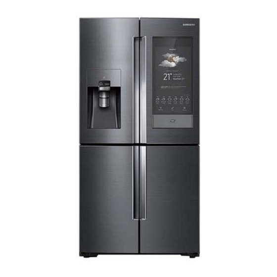
FRENCH DOOR REFRIGERATOR
MODEL NAME:
RF22N* / RF28N*
MODEL CODE:
RF22N9781* / RF28N9780*
1. Precautions (Safety Warnings) ...............5
2. Product Features and Specifications ....9
3. Disassembly and Reassembly ............. 38
4. Troubleshooting ........................................ 73
5. PCB Diagram ........................................... 136
6. Wiring Diagram ...................................... 144
7. Block Diagram ........................................ 145
8. References ................................................ 148
CONTENTS
Advertisement
Table of Contents

Summarization of Contents
Precautions (Safety Warnings)
General Safety Precautions
Essential safety instructions for appliance repair and operation, including electrical safety and proper handling.
Warning Symbols and Specific Warnings
Explanation of warning symbols and specific warnings related to item storage, installation, and environment.
Installation and Moving Safety
Safety guidelines for proper flooring installation and safe movement of the refrigerator unit.
Product Features and Specifications
Compartment Features by Model
Details and illustrations of refrigerator and freezer compartment components for different models.
Basic Product Specifications
Key technical specifications including dimensions, power, refrigerant, and capacity for RF22N* and RF28N* models.
Detailed Specifications Comparison
Comprehensive comparison of features, electrical parts, and internal components across models.
Physical Dimensions
Detailed diagrams illustrating external dimensions and door opening clearance for the refrigerator models.
User Interface and Smart Features
Explanation of the refrigerator's display interface, apps, Samsung Connect, and smart home integration features.
Advanced Functions and Components
Description of SMART GRID, Ice Maker function, and material specifications for various components.
Disassembly and Reassembly
Disassembly Precautions and Tools
Safety guidelines and required tools for safely disassembling refrigerator components.
Door and Hinge Disassembly
Step-by-step instructions for removing fridge and freezer doors, and their associated hinge mechanisms.
Internal Component Disassembly
Detailed guides for removing specific components like reed switch, display, dispenser, and water filter.
Evaporator and Lamp Removal
Instructions for removing evaporator covers, internal lamps, and other internal parts.
Ice Maker, Fan, and Sensor Removal
Procedures for disassembling the ice maker assembly, auger motor fan, and humidity sensor.
Display and USB Port Removal
Steps for dismantling the LCD display, its subcomponents, and removing the USB port.
Troubleshooting
Failure Diagnosis Functions
Overview of diagnostic functions for checking system information, panel tests, and fridge operations.
Panel Function Tests
Detailed procedures for accessing and performing various panel tests.
Specific Panel Test Procedures
Step-by-step guides for LCD, Touch, Speaker, USB, Camera, Sensor, Mic, Wi-Fi, BT, and other panel tests.
Fridge Function Tests
Guides for performing fridge-specific tests like system info, load status, self-diagnosis, error history, model options, and force run.
Troubleshooting Symptom Guides
Step-by-step diagnostic methods for common issues like power loss, compressor failure, fan issues, ice maker problems, and display errors.
Voice Recognition Troubleshooting
Guidance on troubleshooting voice recognition functionality, including setup and common issues.
PCB Diagram
Main Board PCB Layout
Detailed layout of the main PCB with identification of various circuit blocks and connectors.
Inverter PCB Layout
Visual layout of the inverter PCB, highlighting key components and their functions for compressor control.
SMPS Board Layout
Diagram showing the SMPS board layout with part positions and descriptions of power supply functions.
Connector Layouts
Pin assignments and layouts for various connectors on the main board, LCD PBA, and SMPS.
PBA Layouts
Layouts of the LCD PBA and Inverter Board, identifying key integrated circuits and functional blocks.
Wiring Diagram
Dispenser Model Wiring Diagram
Comprehensive wiring diagram illustrating electrical connections for the dispenser model.
Block Diagram
Basic Model Block Diagram
Overall block diagram showing the main functional units and their interconnections within the refrigerator.
LCD PBA Block Diagram
Detailed block diagram for the LCD PBA, illustrating its internal processing units and interfaces.
Inverter Block Diagram
Simplified block diagram of the inverter system, showing its connection to the doors and main PBA.
References
Glossary of Technical Terms
Definitions of technical terms and acronyms used throughout the service manual.
Feature Control and Model Conventions
Explanation of French heater control, model numbering conventions, and related features.
General Troubleshooting Guide
Common symptoms and their corresponding troubleshooting actions before contacting a service center.
Smart Connectivity Troubleshooting
Troubleshooting steps for app connectivity, smart grid, and energy management functions.


Need help?
Do you have a question about the RF22N9781 Series and is the answer not in the manual?
Questions and answers