Table of Contents
Advertisement
Quick Links
Advertisement
Table of Contents
Troubleshooting

Related Manuals for NETGEAR GS748Tv6


Summary of Contents for NETGEAR GS748Tv6
- Page 1 Hardware Installation Guide 24-Port or 48-Port Gigabit Ethernet Smart Switch with 2 dedicated SFP Ports and (for model GS748Tv6 only) 2 Copper/SFP Combo Ports Models GS724Tv6 GS748Tv6 NETGEAR, Inc. March 2024 350 E. Plumeria Drive 202-12745-01 San Jose, CA 95134, USA...
- Page 2 See the regulatory compliance document before connecting the power supply. For NETGEAR’s Privacy Policy, visit https://www.netgear.com/about/privacy-policy. By using this device, you are agreeing to NETGEAR’s Terms and Conditions at https://www.netgear.com/about/terms-and-conditions. If you do not agree, return the device to your place of purchase within your return period.
-
Page 3: Table Of Contents
Chapter 1 Introduction Overview....................5 Features....................5 Safety instructions and warnings............7 Chapter 2 Hardware Overview Front panel model GS724Tv6............11 Front panel model GS748Tv6............11 LEDs model GS724Tv6..............11 LEDs model GS748Tv6..............12 Back panel model GS724Tv6............13 Back panel model GS748Tv6............14 RJ-45 ports for 10/100/1000M BASE-T Ethernet connectivity.. -
Page 4: Chapter 1 Introduction
This hardware installation guide is for the following NETGEAR Smart switches with optional Remote/Cloud Management via Insight: • GS724Tv6: This model is a 24-Port 10M/100M/1G Ethernet Smart Switch with 2 dedicated SFP ports and Remote/Cloud management capabilities. • GS748Tv6: This model is a 48-Port 10M/100M/1G Ethernet Smart Switch with 2 dedicated SFP ports, 2 copper/SFP combo ports, and Remote/Cloud management capabilities. -
Page 5: Overview
For more information about application samples, see Applications on page 17. Features The switch supports the following key hardware features: • 24 or 48 Gigabit Ethernet ports Model GS724Tv6 provides 24 Gigabit Ethernet ports ○ ○ Model GS748Tv6 provides 48 Gigabit Ethernet ports, two of which are copper/SFP combo ports •... - Page 6 • Active flow control to minimize packet loss and frame drops. • Half-duplex backpressure control. • Per-port status LEDs and system status LEDs. • NETGEAR green power-saving features: Energy efficiency mode that fully conforms to the IEEE802.3az standard ○ ○ Per-port automatic change to a lower power mode when the port link is down...
-
Page 7: Safety Instructions And Warnings
Before connecting the product to outdoor cables or devices, see https://kb.netgear.com/000057103 for additional safety and warranty information. Failure to follow these guidelines can result in damage to your NETGEAR product, which might not be covered by NETGEAR’s warranty, to the extent permissible by applicable law. - Page 8 • Depending on your product, use only a supplied power adapter or approved power cable: If your product uses a power adapter: ○ If you were not provided with a power adapter, contact your local NETGEAR reseller. ○ The power adapter must be rated for the product and for the voltage and current marked on the product electrical ratings label.
- Page 9 24-Port or 48-Port Gigabit Ethernet Smart Switch with 2 Dedicated SFP Ports ○ If you were not provided with a power cable for your system or for any AC-powered option intended for your system, purchase a power cable approved for your country. ○...
-
Page 10: Chapter 2 Hardware Overview
Hardware Overview This chapter describes the switch hardware features. The chapter includes the following sections: • Front panel model GS724Tv6 • Front panel model GS748Tv6 • LEDs model GS724Tv6 • LEDs model GS748Tv6 • Back panel model GS724Tv6 • Back panel model GS748Tv6 •... -
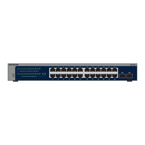
Page 11: Front Panel Model Gs724Tv6
Ethernet cables from the combo ports before using the ports with any transceiver modules. Figure 2. Front panel model GS748Tv6 LEDs model GS724Tv6 This section describes the LEDs on the front panel of the GS724Tv6 switch. Hardware Overview Hardware Installation Guide... -
Page 12: Leds Model Gs748Tv6
24-Port or 48-Port Gigabit Ethernet Smart Switch with 2 Dedicated SFP Ports Table 1. Front panel LEDs Description Power LED Off: Power is not being supplied to the switch. Solid green: The switch is powered on and operating normally. Solid yellow: The switch is booting. RJ-45 port LED Link, Off: No link is established. -
Page 13: Back Panel Model Gs724Tv6
Back panel model GS724Tv6 The back panel provides a Kensington lock and AC power receptacle. (The switch integrates a fixed, internal power supply.) The following figure shows the back panel. Figure 3. Back panel model GS724Tv6 Hardware Overview Hardware Installation Guide... -
Page 14: Back Panel Model Gs748Tv6
24-Port or 48-Port Gigabit Ethernet Smart Switch with 2 Dedicated SFP Ports Back panel model GS748Tv6 The back panel provides a Kensington lock and AC power receptacle. (The switch integrates a fixed, internal power supply.) The following figure shows the back panel. Figure 4. -
Page 15: Sfp Ports For Fiber Or Copper Connectivity
1G or 100M fiber connectivity. GBICs are sold separately from the switch. Ports 25F and 26F on the GS724Tv6 switch and ports 47F-50F on the GS748Tv6 switch support the following NETGEAR SFP transceiver modules: Table 4. -
Page 16: Restart (Power-Cycle) The Switch
NOTE: We recommend that you export and save the configuration file before you restart the switch. To restart the switch using the Reset/Factory Defaults button (model GS724Tv6) or Reset button (model GS748Tv6): 1. Insert a tool such as a straightened paper clip into the opening. -
Page 17: Chapter 3 Applications
Applications This chapter includes the following sections: • Connect equipment in a business environment... -
Page 18: Connect Equipment In A Business Environment
24-Port or 48-Port Gigabit Ethernet Smart Switch with 2 Dedicated SFP Ports Connect equipment in a business environment The following figure shows an example of how you can connect equipment (servers, laptops, storage devices, access points) to the switch in a business environment, providing up to 1 Gbps speed to your business devices. -
Page 19: Chapter 4 Installation
Installation This chapter describes the installation procedures for the switch. Switch installation involves the steps described in the following sections: • Step 1: Prepare the site • Step 2: Protect against electrostatic discharge • Step 3: Unpack the switch • Step 4: Mount or place the switch •... -
Page 20: Step 1: Prepare The Site
24-Port or 48-Port Gigabit Ethernet Smart Switch with 2 Dedicated SFP Ports Step 1: Prepare the site Before you install the switch, make sure that the operating environment meets the site requirements that are listed in the following table. Table 5. Site requirements Characteristics Requirements Mounting... -
Page 21: Step 2: Protect Against Electrostatic Discharge
• Handle all sensitive components in a static-safe area. If possible, use antistatic floor pads, workbench pads, and an antistatic grounding strap. Step 3: Unpack the switch The following figures show the package contents for the two model switches. Figure 6. Switch package contents for model GS724Tv6 Installation Hardware Installation Guide... - Page 22 • Rubber protection caps, which are already installed in the SFP sockets. If you install an SFP transceiver module, you must remove the cap from the SFP socket. • Installation guide If any item is missing or damaged, contact your local NETGEAR reseller for replacement. Installation...
-
Page 23: Step 4: Mount Or Place The Switch
24-Port or 48-Port Gigabit Ethernet Smart Switch with 2 Dedicated SFP Ports Step 4: Mount or place the switch You can mount the switch in a standard 19-inch (48.26-centimeter) network equipment rack or place the switch on a flat surface. Mount the switch in a rack To install the switch in a rack, you need the rack-mount brackets and screws supplied with the switch. - Page 24 5. Tighten the screws with a No. 2 Phillips screwdriver to secure the mounting brackets to the rack. Figure 8. GS724Tv6 rack mount Figure 9. GS748Tv6 rack mount Installation...
-
Page 25: Place The Switch On A Flat Surface
The following optional procedure describes how to install an optional SFP transceiver module into one of the SFP ports of the switch. NOTE: Contact your NETGEAR sales office to purchase these modules. If you do not want to install an SFP module, skip this procedure. -
Page 26: Step 6: Connect Devices To The Switch's Rj-45 Ports
24-Port or 48-Port Gigabit Ethernet Smart Switch with 2 Dedicated SFP Ports CAUTION: Be sure that you insert the module the correct way into the port. There is only one way to insert the module. If it does not fit, you might be holding the module upside down. -
Page 27: Step 7: Check The Installation
LEDs for attached devices light. For information about the LEDs, see LEDs model GS724Tv6 on page 11 and LEDs model GS748Tv6 on page 12. If the Power LED does not light, check that the power cord is plugged in correctly and the power source is good. -
Page 28: Step 9: Manage The Switch
• NETGEAR Insight app and Insight Cloud Portal: If you set the management mode of the switch to NETGEAR Insight Mobile App and Insight Cloud Portal, you can use the following applications to manage the switch remotely: ○... - Page 29 24-Port or 48-Port Gigabit Ethernet Smart Switch with 2 Dedicated SFP Ports NOTE: If you plan to use the NETGEAR Insight Cloud Portal or Insight app to manage the switch, we recommend that you do not use the device UI to...
-
Page 30: Chapter 5 Troubleshooting
Troubleshooting This chapter provides information about troubleshooting the switch. The chapter includes the following sections: • Troubleshooting chart • Additional troubleshooting suggestions... -
Page 31: Troubleshooting Chart
24-Port or 48-Port Gigabit Ethernet Smart Switch with 2 Dedicated SFP Ports Troubleshooting chart The following table lists symptoms, possible causes, and possible solutions for problems that might occur. Table 6. Troubleshooting chart Symptom Possible Cause Possible Solution The Power LED is off. Power is not supplied to •... -
Page 32: Additional Troubleshooting Suggestions
• Switch integrity: If necessary, verify the integrity of the switch by restarting it. To restart the switch, disconnect the power from the switch and then reconnect the power. If the problem continues, contact NETGEAR technical support. For more information, visit the support website at netgear.com/support/.
Need help?
Do you have a question about the GS748Tv6 and is the answer not in the manual?
Questions and answers