
Related Manuals for Vents NK 125


Summary of Contents for Vents NK 125
- Page 1 USER'S MANUAL NK 100 NK 400 * 200 NK 125 NK 500 * 250 NK 150 NK 500 * 300 NK 160 NK 600 * 300 NK 200 NK 600 * 350 NK 250 NK 700 * 400 NK 315...
-
Page 2: Table Of Contents
Do not use the unit in a hazardous or explosive environment containing spirits, gasoline, insecticides, etc. Do not close or block the intake or extract vents in order to ensure the efficient air flow. Do not sit on the unit and do not put objects on it. - Page 3 This unit is not intended for use by persons (including children) with reduced physical, sensory or mental capabilities, or lack of experience and knowledge, unless they have been given supervision or instruction concerning use of the unit by a person responsible for their safety. Children should be supervised to ensure that they do not play with the unit.
-
Page 4: Purpose
PURPOSE Duct heaters are designed for heating of intake fresh air transported through the ventilating system. The unit is a component part and is not designed for independent operation. The heater is designed for extended periods of continuous operation without disconnection from the power mains. Transported air must not contain any flammable or explosive mixtures, evaporation of chemicals, sticky substances, fibrous materials, coarse dust, soot and oil particles or environments favourable for the formation of hazardous substances (toxic substances, dust, pathogenic germs). -
Page 5: Technical Data
The heater design is constantly improved, so some models may slightly differ from the ones depicted herein. OVERALL AND CONNECTING DIMENSIONS OF HEATERS FOR ROUND DUCTS Dimensions [mm] Heater model NK 100-0,6-1 NK 100-0,8-1 NK 100-1,2-1 NK 100-1,6-1 NK 100-1,8-1... - Page 6 Dimensions [mm] Heater model NK 160-2,4-1 NK 160-3,4-1 NK 160-3,6-3 NK 160-5,1-3 NK 160-6,0-3 NK 200-1,2-1 NK 200-1,7-1 NK 200-2,0-1 NK 200-2,4-1 NK 200-3,4-1 NK 200-3,6-3 NK 200-5,1-3 NK 200-6,0-3 NK 250-1,2-1 NK 250-2,0-1 NK 250-2,4-1 NK 250-3,0-1 NK 250-3,6-3 NK 250-6,0-3 NK 250-9,0-3 NK 315-1,2-1...
- Page 7 Number of electric Current Minimum air flow Heater model Power [kW] Number of phases Voltage [V] heating elements x Weight [kg] power [kW] NK 100-0,6-1 1x0.6 NK 100-0,8-1 1x0.8 NK 100-1,2-1 2x0.6 NK 100-1,6-1 2x0.8 NK 100-1,8-1 3x0.6 NK 125-0,6-1 1x0.6...
- Page 8 OVERALL AND CONNECTING DIMENSIONS OF HEATERS FOR RECTANGULAR DUCTS Dimensions [mm] Heater model NK 400*200-4,5-3 NK 400*200-6,0-3 NK 400*200-7,5-3 NK 400*200-9,0-3 NK 400*200-10,5-3 NK 400*200-12,0-3 NK 400*200-15,0-3 NK 500*250-6,0-3 NK 500*250-7,5-3 NK 500*250-9,0-3 NK 500*250-10,5-3 NK 500*250-12,0-3 NK 500*250-15,0-3 NK 500*250-18,0-3 NK 500*250-21,0-3 NK 500*300-6,0-3 NK 500*300-7,5-3...
- Page 9 Dimensions [mm] Heater model NK 600*300-15,0-3 NK 600*300-18,0-3 NK 600*300-21,0-3 NK 600*300-24,0-3 NK 600*350-9,0-3 NK 600*350-12,0-3 NK 600*350-15,0-3 NK 600*350-18,0-3 NK 600*350-21,0-3 NK 600*350-24,0-3 NK 700*400-18,0-3 NK 700*400-27,0-3 NK 700*400-36,0-3 NK 800*500-27,0-3 NK 800*500-36,0-3 NK 800*500-54,0-3 NK 900*500-45,0-3 1040 NK 900*500-54,0-3 1040 NK 1000*500-45,0-3 1140...
- Page 10 MAIN TECHNICAL PARAMETERS OF HEATERS FOR RECTANGULAR DUCTS Number of electric Number of Current Minimum air Weight Heater model Power [kW] Voltage [V] heating elements x phases flow [m [kg] power [kW] NK 400*200-4,5-3 3x1.5 NK 400*200-6,0-3 3x2.0 NK 400*200-7,5-3 3x2.5 10.9 NK 400*200-9,0-3...
-
Page 11: Design And Operating Principle
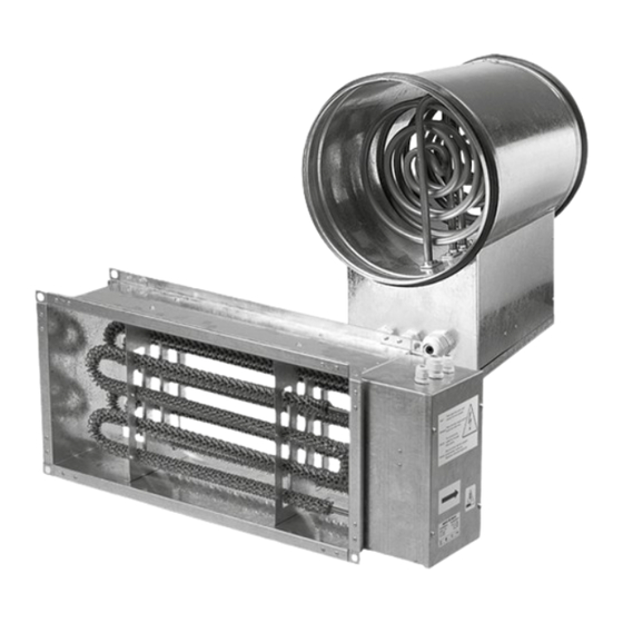
DESIGN AND OPERATING PRINCIPLE The heaters (see the figure below) consist of a casing with a rigidly fixed connecting box that is with the removable cover. The tight seals are located at the external side of the connection box for routing of supply, control and ground cables. The heating elements are located inside the casing. -
Page 12: Mounting And Set-Up
MOUNTING AND SET-UP READ THE USER'S MANUAL BEFORE INSTALLING THE UNIT. Disconnect the unit from power supply prior to any connection, servicing and repair operations. Prior to the heater installation check the heater for the integrity and reliability of the heating element fixation. The heater shall be installed in the air duct with the same diameter (dimensions). - Page 13 CONNECTING ROUND AIR DUCTS TO THE HEATER The heater is designed for internal installation into air ducts in the horizontal or vertical position. In a horizontal position the connection box must face upwards. Permitted deviation up to 90 °C. The heater must not be mounted with the connection box suspended downwards (risk of condensate leaking and short circuit of power grid).
-
Page 14: Connection To Power Mains
CONNECTION TO POWER MAINS POWER OFF THE POWER SUPPLY PRIOR TO ANY OPERATIONS WITH THE UNIT. THE UNIT MUST BE CONNECTED TO POWER SUPPLY BY A QUALIFIED ELECTRICIAN. THE RATED ELECTRICAL PARAMETERS OF THE UNIT ARE GIVEN ON THE MANUFACTURER’S LABEL. ANY TAMPERING WITH THE INTERNAL CONNECTIONS IS PROHIBITED AND WILL VOID THE WARRANTY. - Page 15 WIRING DIAGRAM OF THE HEATER WITH TWO ELECTRICAL HEATING ELEMENTS AND SINGLE-PHASE POWER SUPPLY T° T° RESET E1, E2 WIRING DIAGRAM OF THE HEATER WITH THREE ELECTRICAL HEATING ELEMENTS AND SINGLE-PHASE POWER SUPPLY T° T° RESET E1, -E2, -E3 www.ventilation-system.com...
- Page 16 WIRING DIAGRAM OF THE HEATER WITH THREE ELECTRICAL HEATING ELEMENTS AND THREE-PHASE POWER SUPPLY RESET RESET T° T° RESET www.ventilation-system.com...
- Page 17 WIRING DIAGRAM OF THE HEATER WITH SIX ELECTRICAL HEATING ELEMENTS AND THREE-PHASE POWER SUPPLY, STAR CONNECTION AND THERMAL PROTECTION CONTACTS LEADED OUTSIDE T° T° RESET WIRING DIAGRAM OF THE HEATER WITH SIX ELECTRICAL HEATING ELEMENTS, THREE-PHASE POWER SUPPLY, DELTA CONNECTION AND THERMAL PROTECTION CONTACTS LEADED OUTSIDE °...
- Page 18 WIRING DIAGRAM OF THE HEATER WITH ONE ELECTRICAL HEATING ELEMENT, SINGLE-PHASE POWER SUPPLY AND TIME-DELAY RELAY Rezistenta T° T° RESET WIRING DIAGRAM OF THE RECTANGULAR HEATER WITH THREE ELECTRICAL HEATING ELEMENTS, THREE-PHASE POWER SUPPLY, STAR CONNECTION AND TIME-DELAY RELAY L1L2 L3 Rezistenta T°...
- Page 19 WIRING DIAGRAM OF THE RECTANGULAR HEATER WITH THREE ELECTRICAL HEATING ELEMENTS, THREE-PHASE POWER SUPPLY, DELTA CONNECTION AND TIME-DELAY RELAY L1L2 L3 Rezistenta ° ° RESET WIRING DIAGRAM OF THE RECTANGULAR HEATER WITH THREE ELECTRICAL HEATING ELEMENTS, THREE-PHASE POWER SUPPLY, STAR CONNECTION AND TIME-DELAY RELAY L1L2 L3 Rezistenta T°...
-
Page 20: Technical Maintenance
TECHNICAL MAINTENANCE DISCONNECT THE UNIT FROM POWER SUPPLY BEFORE ANY MAINTENANCE OPERATIONS! MAKE SURE THE UNIT IS DISCONNECTED FROM POWER MAINS BEFORE REMOVING THE PROTECTION. The heaters shall be operated and maintained by duly qualified experts. Check the following conditions during the unit maintenance: •... -
Page 21: Manufacturer's Warranty
MANUFACTURER’S WARRANTY The product is in compliance with EU norms and standards on low voltage guidelines and electromagnetic compatibility. We hereby declare that the product complies with the provisions of Electromagnetic Compatibility (EMC) Directive 2014/30/EU of the European Parliament and of the Council, Low Voltage Directive (LVD) 2014/35/EU of the European Parliament and of the Council and CE-marking Council Directive 93/68/EEC. - Page 22 www.ventilation-system.com...
-
Page 23: Certificate Of Acceptance
CERTIFICATE OF ACCEPTANCE Unit Type Duct heater Model Serial Number Manufacture Date Quality Inspector’s Stamp SELLER INFORMATION Seller Address Phone Number E-mail Purchase Date This is to certify acceptance of the complete unit delivery with the user’s manual. The warranty terms are acknowledged and accepted. - Page 24 V09EN-10...
Need help?
Do you have a question about the NK 125 and is the answer not in the manual?
Questions and answers