Advertisement
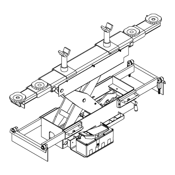
X14/XA14 Rolling Jack
General Description......................................................................................................... 3
Specifications ................................................................................................................... 4
Installation......................................................................................................................... 5
Maintenance Instructions .............................................................................................. 9
Safety Instructions........................................................................................................... 11
Operating Instructions .................................................................................................... 11
Maintenance Instructions .............................................................................................. 12
Trouble Shooting .............................................................................................................. 13
Parts Breakdown ............................................................................................................. 16
© June 2019 by Rotary Lift. All rights reserved.
7,000 Lb. Capacity
Table of Contents
CO10951.3
I
I
N
N
S
S
T
T
A
A
L
L
L
L
A
A
T
T
I
I
O
O
N
N
-
-
S
S
A
A
F
F
E
E
T
T
Y
Y
-
-
O
O
P
P
E
E
R
R
A
A
T
T
I
I
O
O
N
N
-
-
M
M
A
A
I
I
N
N
T
T
E
E
N
N
A
A
N
N
C
C
E
E
IN20843
Rev. B 6/3/2019
Advertisement

Related Manuals for Rotary XA14

Summarization of Contents
1. GENERAL DESCRIPTION
1.1 Description of the machine
Hydraulic wheel free jack with mechanical stop.
1.2 Purpose of the machine
Designed to support and lift vehicles already on a lift.
1.3 Wheel free jack controls
Identifies mechanical stop (A) and elevation pedal (B) controls.
1.4 Main technical specifications
Lists key technical features like overload valve and sliding rollers.
2. AFTER UNPACKING
2.1 Moving to site
Procedure for moving the machine to the installation area using a fork-lift.
2.2 Disposal of the packaging
Instructions for safely disposing of packaging materials.
3. INSTALLATION
3.1 Checking that all the parts are present
Verify all parts are received before starting assembly and installation.
3.2 Checking the minimum requirements for the place of installation
Check area for light, weather, and pollution for proper installation.
3.3 Pneumatic connection
Ensure air supply pressure does not exceed 10 bar; use filtered air.
3.4 Instructions for installation
Step-by-step guide for positioning the jack onto the lift platform.
Holder brackets adjustment
Procedure for adjusting holder brackets, including shims and checking clearances.
3.5 First start up of the machine
Process for initial machine start-up and testing by authorized staff.
4 INSTRUCTIONS FOR USE
4.1 Precautions for use and training of operating staff
Emphasizes trained personnel, safety procedures, and prohibitions for operation.
4.2 Description of controls
Details the operation of safety pin, vehicle positioning, and jack controls (Up/Down).
5. DESCRIPTION AND FUNCTION OF THE SAFETY COMPONENTS
5.1 Warning
Highlights the importance of safety components for proper operation and warns against modifications.
5.2 Mechanical stop device
Explains the threaded ring nut for blocking accidental load descent.
5.3 Device for overload protection
Describes the calibration valve to prevent lifting beyond set capacity.
7. MAINTENANCE
7.1 Changing the oil
Procedure and frequency for changing hydraulic oil, including level check.
7.2 Cleaning the valve and filter
Instructions for cleaning the air filter and valve using specific methods.
7.3 Replacement of the piston gaskets
Advises replacing all piston gaskets simultaneously when one needs changing.
7.4 Air drainage
Procedure for draining air from the piston and pump systems.
OPERATING INSTRUCTIONS
1. Before loading a vehicle onto lift
Ensure jacks are lowered, adapters inbound, and rear jack centered.
2. After vehicle has been loaded
Chock tires on the opposite side of the rolling jack to be raised.
3. Place jack under vehicle
Position jack at pick-up points, extend arms, and take up clearance with rubber blocks.
4. To Raise Rolling Jack
Connect air, depress pump lever until desired lock position, lift lever to latches.
5. To Lower Rolling Jack
Raise jack off latches, lift latch release, lift pump lever to lower.
4. Be sure the jack is fully lowered
Ensure jack is lowered, adapters low, bridge pushed forward before vehicle removal.
MAINTENANCE INSTRUCTIONS
Daily: Inspect rolling jack adapters
Daily inspection of adapters for damage or wear; replace with original parts.
Daily: Inspect air/hydraulic system
Daily check of the air/hydraulic system for any signs of leaks.
Daily: Inspect for loose bolts
Daily inspection for loose bolts and damaged components.
Daily: Inspect linkage curtain guard
Daily check of linkage curtain guard for damage or wear.
Monthly: Inspect the roller assemblies
Monthly inspection of the machine's roller assemblies.
Semi-Annually: Check fluid level
Semi-annual check of the hydraulic reservoir fluid level.
11. SPARE PARTS TABLES
11.1 How to order spare parts
Information needed when ordering spare parts, including model and serial number.
11.2 Spare parts summary
Summary of machine main units and references to relevant spare parts tables.
Need help?
Do you have a question about the XA14 and is the answer not in the manual?
Questions and answers