Advertisement
Quick Links
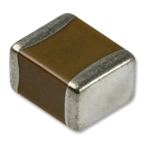
Chip Monolithic Ceramic Capacitor for General
GRM1555C1H102JA01_ (0402, C0G:EIA, 1000pF, DC50V)
_: packaging code
1.Scope
This product specification is applied to Chip Monolithic Ceramic Capacitor used for General Electronic equipment.
2.MURATA Part NO. System
(Ex.)
GRM
15
(1)L/W
Dimensions
3. Type & Dimensions
(1)-1 L
(1)-2 W
1.0±0.05
0.5±0.05
4.Rated value
(3) Temperature Characteristics
(Public STD Code):C0G(EIA)
Temp. coeff
or Cap. Change
0±30 ppm/°C
5.Package
mark
(8) Packaging
f180mm Reel
D
PAPER W8P2
f180mm Reel
W
PAPER W8P1
f330mm Reel
J
PAPER W8P2
Product specifications in this catalog are as of Mar.8,2016,and are subject to change or obsolescence without notice.
Please consult the approval sheet before ordering.
Please read rating and !Cautions first.
GRM1555C1H102JA01-01
5
5C
(2)T
(3)Temperature
Dimensions
Characteristics
(2) T
e
0.5±0.05
0.15 to 0.35
(4)
Rated
Temp. Range
Voltage
(Ref.Temp.)
25 to 125 °C
DC 50 V
(25 °C)
Packaging Unit
10000 pcs./Reel
20000 pcs./Reel
50000 pcs./Reel
1H
102
(4)Rated
(6)Capacitance
(5)Nominal
Voltage
Capacitance
(Unit:mm)
g
0.3 min.
Specifications and Test
(6)
(5) Nominal
Capacitance
Capacitance
Tolerance
1000 pF
±5 %
1
Reference Sheet
J
A01
(7)Murata's Control
(8)Packaging Code
Tolerance
Code
Methods
(Operating
Temp. Range)
-55 to 125 °C
D
Advertisement

Related Manuals for Murata GRM1555C1H102JA01D

Summarization of Contents
Specifications and Test Methods
Electrical and Physical Tests
Procedures for rated voltage, IR, capacitance, Q factor, appearance, dimensions, and voltage proof.
Temperature and Termination Tests
Methods for testing temperature characteristics and termination adhesive strength.
Specifications and Test Methods
Vibration and Shock Resistance
Test methods for vibration resistance and substrate bending strength.
Solderability and Heat Resistance
Procedures for testing solderability and resistance to soldering heat.
Temperature Sudden Change
Testing capacitance change after sudden temperature variations.
Specifications and Test Methods
High Temperature High Humidity
Testing performance under high temperature and humidity conditions.
Durability Testing
Methods for assessing capacitor durability under various conditions.
Tape Carrier Packaging
Packaging Codes and Quantities
Details on packaging codes, reel sizes, and minimum quantities per reel.
Tape Dimensions and Specifications
Dimensions and specifications related to tape carrier packaging for components.
Storage and Operation Conditions
Storage Recommendations
Guidelines for storing capacitors to maintain quality and performance.
Rating
Temperature Dependency
Capacitance variation with temperature and circuit selection advice.
Capacitance Measurement and Voltage Application
Capacitance Measurement Procedures
How to measure capacitance, including output voltage and AC voltage considerations.
Applied Voltage Guidelines
Rules for applying DC, AC, and pulse voltages to avoid damage.
Operating Voltage and Self-heating
Managing operating voltage and self-heating to stay within limits.
DC Voltage and AC Voltage Characteristics
Voltage Dependency
How capacitance varies with DC and AC voltage, with examples.
Capacitance Aging
Decrease in capacitance value over time for high dielectric constant types.
Vibration and Shock Considerations
Handling Precautions
Recommendations for avoiding damage from vibration, shock, and handling.
Soldering and Mounting
Mounting Position and Stress Minimization
Best practices for mounting to reduce stress from flexing, bending, and separation.
Pre-Mounting Information
Key information to confirm before mounting components.
Mounting Machine Maintenance
Preventing Excessive Force
Adjustments for pick-up nozzles and pressure to avoid damaging capacitors.
Nozzle and Claw Maintenance
Importance of cleaning and maintaining machine parts for smooth operation.
Reflow Soldering
Soldering Process and Conditions
Requirements for preheating, soldering, cooling, and solvent immersion.
Solder Amount and Fillet
Importance of correct solder amount to prevent cracking.
Flow Soldering
Soldering Procedures and Limitations
Guidelines for flow soldering, including chip compatibility and temperature differentials.
Solder Amount for Flow
Optimal solder amount to avoid cracking and ensure adhesion.
Soldering Corrections
Soldering Iron Rework
Procedures for correcting soldered portions with a soldering iron, including preheating.
Spot Heater Rework
Using a spot heater for rework, including distance and angle recommendations.
Optimum Solder Amount for Rework
Guidelines on solder amount for rework to prevent cracking or detachment.
Cleaning, Testing, and Cropping
Washing and Electrical Testing
Precautions for PCB cleaning and electrical testing procedures.
PCB Cropping Guidelines
Preventing stress during PCB cropping and selecting appropriate methods.
PCB Separation Methods
Single-Side Mounting Jigs
Examples of jigs for minimizing stress during board separation on single-sided PCBs.
Disc Separator Operation
Principles and potential issues with disc separators for PCB separation.
Assembly and Component Handling
Router Separator Example
Using router separators to suppress stress during board separation.
General Handling Precautions
Avoiding bending, dropping, or excessive force during assembly.
Component Mounting and Insertion
Precautions for mounting other components and inserting leads into boards.
Operational Precautions and Other Information
Equipment Operation Guidelines
Safety precautions during operation, environmental conditions, and condensation countermeasures.
Emergency, Disposal, and Design
Procedures for emergencies, waste disposal, circuit design, and general remarks.
Rating and Environmental Factors
Operating Temperature and Self-Heating
Managing operating temperature limits and self-heating effects.
Atmosphere and Piezoelectric Effects
Restrictions on operating environments and potential noise from piezoelectric effects.
PCB Design for Soldering and Mounting
Pattern Form Considerations
Designing land patterns and dimensions to prevent excess solder fillet height and chip cracking.
Thermal Expansion and Stress
Managing PCB material and structure to prevent cracking due to thermal expansion differences.
Land Dimensions for Soldering
Land Area and Solder Amount
Importance of correct land dimensions and solder amount to prevent PCB bending stress.
Board Design and Adhesive Application
Strain and Board Design
How board size, material, and thickness affect strain and potential cracking.
Adhesive Properties and Curing
Requirements for adhesive amount, viscosity, coverage, and curing for proper bonding.
Flux for Flow Soldering
Flux Usage Guidelines
Recommendations for flux type, amount, and halide content for flow soldering.
Soldering, Washing, and Coating
Soldering Process Details
Requirements for flow and reflow soldering, including flux and termination leaching.
Cleaning and Coating Precautions
Guidelines for cleaning solvents and coating resins to ensure capacitor reliability.
Transportation and In-System Evaluation
Transportation Guidelines
Protecting capacitors from environmental and mechanical stress during transport.
Actual System Performance Evaluation
Evaluating capacitor performance in the target system, considering dependencies.
Need help?
Do you have a question about the GRM1555C1H102JA01D and is the answer not in the manual?
Questions and answers