
Related Manuals for SolarEast BLN-012TC1


Summary of Contents for SolarEast BLN-012TC1
- Page 1 #290 BLN-006TC1 BLN-012TC1/BLN-012TC3 BLN-018TC1/BLN-018TC3 Air Source Heat Pump Heat Pump for Heating & Cooling & DHW Please read this manual carefully before using it and keep it in a safe place.
-
Page 2: Table Of Contents
Note 1. Please read the instruction manual carefully before installation or operation. 2. The heat pump must be installed by a professional installer. 3. Please follow the instruction manual strictly when installing the heat pump 4. If any update on the product, this instruction manual is subject to change without notice 5. -
Page 3: User Instruction
User Instructions 2. Make sure that the leakage protection switch Please use an electrical leakage switch, is securely connected. If the wiring is not otherwise, there may be electric shock, fire, secure, it may cause electric shock, heat, or etc. fire. - Page 4 R290 Warning This appliance uses R290 (propane) refrigerant, which is a flammable gas and must be serviced by an authorized person. WARNING Risk of fire/flammable material. If the refrigerant is leaking, switch off the unit at the mains and contact the service agent.
- Page 5 1. Precautions Please make sure that you have read this manual before using our air source heat pump. In the “User Information” chapter, “User Information” provides essential safety information. Please be sure to follow the instruction strictly. Wrong operations are likely to cause serious consequences such as death, serious Warning injury, or major accidents Improper operation may result in a safety accident, damage to the machine, or...
- Page 6 Note 1) Do not put your hands or other objects into the air outlet of the machine. Otherwise, the fan running at high speed may cause harm. 2) Do not remove the fan cover. Otherwise, the fan running at high speed may cause injury to you or others.
- Page 7 refrigerant charge. The maximum number of pieces of equipment permitted to be stored together will be determined by local regulations. 6) Information on servicing: i. Checks to the area Prior to beginning work on systems containing flammable refrigerants, safety checks are necessary to ensure that the risk of ignition is minimized.
- Page 8 --Refrigeration pipes or components are installed in a position where they are unlikely to be exposed to any substance which may corrode refrigerant-containing components unless the components are constructed of materials that are inherently resistant to being corroded or are suitably protected against being so corroded. ix.
- Page 9 not be adequate or may need re-calibration. (Detection equipment shall be calibrated in a refrigerant-free area.) Ensure that the detector is not a potential source of ignition and is suitable for the refrigerant used. Leak detection equipment shall be set at a percentage of the LFL of the refrigerant and shall be calibrated to the refrigerant employed and the appropriate percentage of gas (25 % maximum) is confirmed.
- Page 10 • All personal protective equipment is available and being used correctly; • The recovery process is supervised at all times by a competent person; • Recovery equipment and cylinders conform to the appropriate standards. d)Pump down refrigerant system, if possible. e)If a vacuum is not possible, make a manifold so that refrigerant can be removed from various parts of the system.
- Page 11 This manual forms an essential part of the product and it must be given to the user. Read the warnings and recommendations in the manual carefully, as they contain important information on the safety, use, and maintenance of the installation. This heat pump must be installed by qualified personnel only, in accordance with the legislation in force and following the manufacturer’s instructions.
-
Page 12: Operation Instructions
Operation Instruction Operating instructions for the wire controller: 1.Wire controller button illustration 2.LCD wire controller 2.1、Connect the power ,as following picture shows,Select the corresponding language option and click“ ”enter the system,If no language is selected within 2 minutes, the system automatically enters the system based on the current language. After entering the system, display the following page ,The normal page is displayed after 3 seconds3S,If the communication fails, the display remains,Touch is accompanied by the sound of keys,If the bright screen... - Page 13 2.2、Main interface display...
- Page 14 2.2.1、Icon description The main interface shows from left to right at the top of the main interface: time, day-month-year, week, frost, grade couplet, mute, water pump, water return valve, electric heating, compressor, fan, wifi; Mode/turn off display:In the state of power on,Display the current running mode on the left of the main interface;Do not display the running mode when power off:...
- Page 15 DHW+Heating DHW+Underfloor heating DHW+Cooling Fault display: When there is a unit failure, “ ”blinking display,You can click this icon to view real-time faults or fault records; Frost shows:When the unit enters defrosting, “ ”Always bright display;Flash display when refrigerant recovery is running; Cascading display:...
- Page 16 Eclectic heater display:When the electric heater starts,“ ”Always bright display;When the electric heater does not start and the quick heating function is enabled,1Hz blinking display;When the electric heating does not start and open the sterilization function,0.5Hz blinking display; Compressor display:When the compressor starts, “...
- Page 17 3.3. temperature setting...
- Page 18 3.3.1、Single mode (heating, cooling, floor heating, hot water),can click“+”“-”Adjust the setting temperature of the current mode;Or the slider can also set the setting temperature of the current mode;Or click Set temperature value,Enter the setting temperature on the keyboard that pops up,press“Enter” “Enter”to modify;...
- Page 19 3.3.2、In combination mode,Click Set temperature value,Enter set temperature press on the keyboard that pops up“Enter”to modify; 3.4. rapid heating、silence、Forced frost、System emptying、High temperature sterilization function: In the bright screen in the main interface,click“ ”enter the function selection pate;and then click “ ”Enter the user command operation,From the top to down issilent mode、...
- Page 20 3.6.Test mode: On the bright screen,click“ ”to go to the function selection page;and then click“ ”, Type on the keyboard that pops up“1122”, Press“Enter”Enter to factory function,and then click“ ”E nter Factory test interface,On this screen, you can manually control the running status of the compressor, fan, EEV, and EVI, and enter the IPLV test mode.
- Page 21 press“Enter”enter to to factory function,and then long press more than 3S“ ”En ter refrigerant recovery. 3.9.Querying Running Parameters 3.9.1. On the bright screen,Press“ ”into the Query Page,and then click“ ”into viewing the Temperature Status;When the network is running, press“ ”Enter the number selection,Click the corresponding online unit number to enter the temperature status query of the corresponding unit。Units in gray are not online.
- Page 22 3.10.parameter setting 3.10.1. On the bright screen,press“ ”enter the setting page , click“ ”enter parameter setting page;When the network is running, press“ ”E nter the group number selection, Click the corresponding online unit number to enter the parameter setting of the corresponding unit,Units in gray are not online.
- Page 23 At this time can press“ ”“ ” check the value of each parameter, Click the parameter to be modified. The page for modifying parameters is displayed,In this page can be realistic parameter number、Current Parameter Values、set value、setting range,Click the parameter value on the keyboard that pops up to enter the set value by pressing“Enter”,Click again on the following page“Enter”Save the parameters。...
- Page 24 3.11. Display fault: When the unit is faulty,“ ”Blinking icon Display,When the fault is disappear,Icon out; Click the icon to go to the fault query page; A maximum of 20 faults and 50 historical faults can be realized,00E03:00 means master unit, 02.03..means slave unit, E03 means Error code Click“...
- Page 25 query 3.12. clock setting: On the bright screen,press“ ”Enter the setting page,and click“ ”enter the time setting page, Click the corresponding year, month and day to enter the value on the keyboard,finally press“Enter”save time;...
- Page 26 3.13. set the on/off timing control On the bright screen,click“ ”Enter the function selection page;and then click“ ”enter on/off timming check page;If you need to enable weekly timingClick any button from Monday to Sunday to start the weekly timing;Click the time period to enter the time setting of the time period,From keyboard to input the time,Click the Enable button“...
- Page 27 3.14.return water temperature setting On the bright screen,click“ ”enter the function selection page;and then click“ ”en ter backwater timming check setting page.
- Page 28 3.15.WIFI distribution network On the bright screen,click“ ”enter the The function selection page;and then click“ ”enter WIFI operation interface;Press and release the button for more than 3S to enter the corresponding WIFi distribution mode,WIFI with 3min,Timeout exit 3.16.scene setting On the bright screen, click“ ”enter function selection page;...
- Page 29 or weekly cycle timing。click“ ”You can enable or disable this scenario setting。 Click the scene segment to be modified to modify the scene,Click on the pattern area“ ”can change the mode, Click the corresponding value to modify it by keyboard input, click“...
- Page 30 3.17Modifying User Parameters Set temperature, return difference, return water temperature, kill virus On the bright screen,press“ ”enter the Query Page,and click“ ”enter userparameter list, For details, see Factory Parameter Settings. 3.18.Parameter Query of Power module (optional) When the unit is equipped with a battery module, On the bright screen,press“...
- Page 31 On the bright screen,press“ ”enter the Query Page,and click“ ”Enter curve Query, Records the curves of the inlet water, outlet water, compressor frequency, and ambient temperature within 24 hours 3.20.Curve setting On the bright screen,press“ ”enter the Query Page,and click“ ”Enter curve setting, click“...
- Page 32 3.21.brightness Settings On the bright screen,press“ ”enter the setting page ,and click“ ”enter the brightness Settings page ,Slide the slider to set different brightness;click“ ”“ ”Switch different languages, Chinese, English, Polish.
- Page 33 3.22.restore factory setting On the bright screen,press“ ”enter the setting page. ,and click“ ”enter the restore factory setting page,and click“ ”It can restore factory Settings. 3.23. Check Program version...
-
Page 34: Dimension
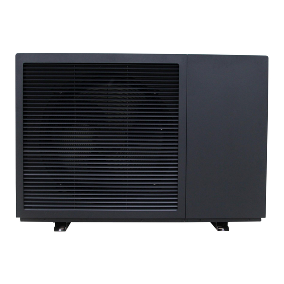
On the bright screen,press“ ”enter the setting page ,and click“ ”You can view the program version numbers of the display and mainboard. Operation Parameter Query Query Code Description Range Compressor Running Frequency 0 ~ 150 Hz Fan Motor Running Frequency 0 ~ 999 Hz Electronic expansion valve steps 0 ~ 480 P... - Page 35 1. Dimension Model Packed Dimensions (mm) BLN-006TC1 1218×470×950 BLN-012TC1 1317*493*1020 BLN-012TC3 1317*493*1020...
- Page 37 Product Packed Model Dimensions (mm) Dimensions (mm) BLN-018TC1 1285×455×1350 1217*538*1570 BLN-018TC3 1285×455×1350 1217*538*1570...
- Page 38 2. Explosive Diagram Number Description Number Description Front right panel Compressor Front left panel Base panel Components Air outlet grille Plate heat exchanger Baffle Plate heat exchanger refrigerant Maintenance panel Plate heat exchanger inlet pipe Fan blade Plate heat exchanger refrigerant Fan motor Water pump Motor bracket...
-
Page 39: Installation
The material and thickness of the insulation pipe meet the specified requirements. Otherwise, heat loss and condensation will be caused. b) Please refer to this manual's “Electrical Installation” description section for wire size selection. Model The water inlet/outlet size BLN-006TC1 DN25 (1’’) BLN-012TC1 DN25 (1’’) - Page 40 BLN-012TC3 DN25 (1’’) BLN-018TC1 DN25 (1’’) BLN-018TC3 DN40 (1.5’’) BLN-006TC1 DN40 (1.5’’) 1.3 Other Installation Materials Fix the pipe bracket and pipe clamp of the connecting pipe Wire threading pipe and pipe clamp Insulting tape, raw tape Expansion bolt Mounting bracket 2.
- Page 41 Installation In The Following Locations May Cause The Machine To Malfunction: 1. A place with more oil; 2. Wet place 3. Seaside saline-alkali area; 4. Special environmental conditions; 5. High-frequency facilities such as wireless equipment, welding machines, and medical equipment. 3.
- Page 42 Remarks: 1. Hydraulic calculation must be carried out after the primary water pipe selection is completed. If the waterside pipeline resistance is more excellent than the selected pump lift, the larger water pump must be re-selected, or the water pipe must be increased in size; 2.
- Page 43 drain valve has water overflow, and if there is water overflow, it means that the water in the system has been filled; 4.4.4 Close the pressure relief valve, and then look at the water pressure gauge. If the pressure value is more than 0.15Mpa, please close the feed-water valve and complete the water drain.
- Page 44 7. Do not send power before the wiring is completed to avoid personal injury; 8. The supply voltage should vary within ±10% of the standard value. 9. Electrical specifications: Model BLN-006TC1 BLN-012TC1 BLN-018TC1 Power Supply 220~240 V/ 1/ 50 Hz Max Input Current (A) 35.50...
- Page 45 Motherboard Output Definitions Seq. Port Description Seq. Port Description Hot Water Electric Heating Low-Pressure Sensors Four-Way Valve Outer Coil Temperature Liquid Injection Valve Return Air Temperature Reservation Exhaust Temperature Reservation Cooling Coil Temperature Return Water Valve Economizer Inlet Temperature Crankshaft Heating Economizer Outlet Temperature Chassis Heating Outdoor Ambient Temperature...
- Page 46 Linkage Switch COM1 Module Cascade Reservation Extension Modules Reservation DC 12V Power Supply Water Flow Switch EXV1 EEV Main Valve Low Voltage Switch EXV2 Auxiliary Valves High Voltage Switch EXV3 Reservation Water Level Public End EXV4 Reservation High Water Level (Hot Water) Power Input Zero Line Medium Water Level (Hot Power Input T-Phase...
- Page 47 Port Description Port Description OUT1 Circulating Water Pump Forced Hot-Water Switch OUT2 Hot Water Electric Heating OUT3 Air-Conditioning Valve Off Linkage Switch OUT4 Air-Conditioning Valve On OUT5 Hot Water Valve On Water Flow Switch OUT6 Hot Water Valve Off OUT7 Reservation Water Inlet Temperature Chassis Heating...
- Page 48 Wire Diagram...
-
Page 50: Commissioning And Maintenance
Commissioning and Maintenance 1. Precautions Before Commissioning Is the machine adequately installed? Is the wiring and pipe correct? Whether the water pipelines are empty or not? Whether the heat insulation has been perfected? Is the ground wire connected reliably? Whether the power supply voltage matches the rated voltage of the machine? Is there any obstacle in the air inlet and outlet of the machine? Is the safety valve installed correctly? Whether the leakage protector can operate effectively? - Page 51 Power Outage If there is a power outage during operation, the machine will stop running. Before the power outage, the controller automatically memories the ON/OFF status of the device. After re-powering, the controller will send an ON/OFF signal to the device according to the state of memory before the power outage to ensure that the device recovers from the previous status from abnormal power failure.
-
Page 52: Trouble Analysis
Trouble Analysis Error code Fault Description Failure Causes Wrong-Phase Protection Power supply phase sequence error Power Supply Lack Of Phase The power supply is out of phase 1. Circulating pump failed, or water system blocked 2. Water flow switch failed, or opposite installed direction Outside Water Flow Switch Fault 3. - Page 53 Damage to the mainboard or water Water Level Switch Malfunction level sensor Anti-Freeze Sensor Malfunction Damaged motherboard or sensor Water Outlet Sensor Failure Damaged motherboard or sensor Reservation Reservation Damage to the mainboard or water Return Air Sensor One Fault level sensor Damage to the mainboard or water Return Air Sensor Two Fault...
- Page 54 contact Abnormal Communication between Compressor One Driver and Main Control Poor or broken signal cable contact Board Abnormal Communication between Compressor Two Driver and Main Control Poor or broken signal cable contact Board Abnormal Communication between Fan Motor One Driver and Main Control Poor or broken signal cable contact Board Abnormal Communication between Fan...
-
Page 55: Specification
Specification BLN-006 BLN-012 BLN-012T BLN-018 BLN-018 Model: 220~240 220~240 380~415/ 220~240 380~415 Power Supply (V/Ph/Hz) /1/50 /1/50 3/50 /1/50 /3/50 Heating 3.0~9.1 5.5~15.1 5.5~15.1 7.5~22.1 7.5~22.1 Nominal Capacity Heating Power 0.65~2.2 (Max) 1.08~3.9 1.08~3.9 1.5~6.8 1.5~6.8 Input (A7/6℃,W Current 30/35℃) 2.8~9.1 4.5~17.0 1.8~6.9... - Page 56 Rated water flow m³/h 1.00 1.80 1.80 3.00 3.00 Fan quantity Fan motor type DC inverter Compressor DC inverter Circulating pump Inverter type / Built-in IP Class IPX4 Sound pressure at 1m dB(A) distance Max outlet water °C temperature Water piping DN 25 DN 25 DN 25...
-
Page 57: After-Sale Ervice
After-sale Service Relevant state regulations carry out the after-sales service of our products. Within the scope of the warranty period, If the machine is not working correctly under reasonable use, please contact the seller. The user must designate a person to manage and use the unit reasonably and correctly by our company’s “Instructions for Use.”... -
Page 58: Appendix
Appendix for Controller Icon Status Functions or meanings Remark Lights out Currently in off or non-hot water mode Display on/off status Constant flashing Currently in hot water mode on Display on/off status Lights out Currently in off or non-heating mode Display on/off status Constant flashing Currently in heating mode... - Page 59 Constant flashing Photovoltaic mode/solar heating 1 Hz flashing Start PV timing Flashing Currently in shutdown and refrigerant recovery state Constant flashing Currently on and defrosting Constant flashing Enter maintenance status Constant flashing Alarm is currently occurring Constant flashing Current button is locked Constant flashing Compressor operation Constant flashing...
- Page 60 WIFI connection Download and install the software : User registration When using the "smart life" software for the first time, user registration is required. Click the "Create New User" link to enter the registration interface. If you already have an account, just click login.
- Page 61 Enter confirmation code set password Enter the phone number you want t o register and click Next User login After successful registration, the software will jump to the login interface or directly log in successfully, enter the correct "user name" and "password" to log in.
- Page 62 Choose the country Enter the username Enter password Click the login button to log in...
- Page 63 Need to select "Agree" The phone needs to be connected to the network through the WIFI network...
- Page 64 Turn on "WLAN" Connect to available Wi-Fi networks This WIFI is not the WIFI in the module but the WIFI that can be connected to the Internet; After users log in to the software, they can add devices Device binding Click "+"...
- Page 65 Click to enter the "Add Device Type" interface...
- Page 66 Choose "Icon Logo" After completing the "Select Device Type", enter the "Add Device Interface", and the network configuration methods are divided into "default mode (WI-FI fast connection)" and "compatibility mode (hotspot distribution network)" Default mode (WI-FI fast connection):...
- Page 67 Enter the Wi-Fi password The remote controller simultaneously press the up key + mode key for 3 seconds to enter the Enter and click "default mode" distribution to confirm network...
- Page 68 Device name can be modified Enter the password and confirm it will Click Finish to start jump to the device control connection interface If the network distribution fails, the APP will display the page as shown in Compatibility mode : the figure, you can choose to re-add or view the help.
- Page 69 Press and hold the timing key +,down key +,power key simultaneously for 3 seconds to enter the "compatibility mode" distribution network. Select "Hot Spot Distribution Network" Click Go to connect and jump to the Wi-Fi After selecting and connecting, return to the interface, select Wi-Fi with the words interface enter...
- Page 70 Enter the correct password and click confirm Control introduction...
- Page 71 Successfully bound device Click to enter control Equipment details Set temperature, and current inlet water temperature display Set temperature adjustment Timing setting, can set the Switch machine control timing on or off Equipment working mode selection...
Need help?
Do you have a question about the BLN-012TC1 and is the answer not in the manual?
Questions and answers